Week 7 State of charge estimation
1)Aim:
To prepare the report of various test cases of the Battery Management algorithms.
Model:
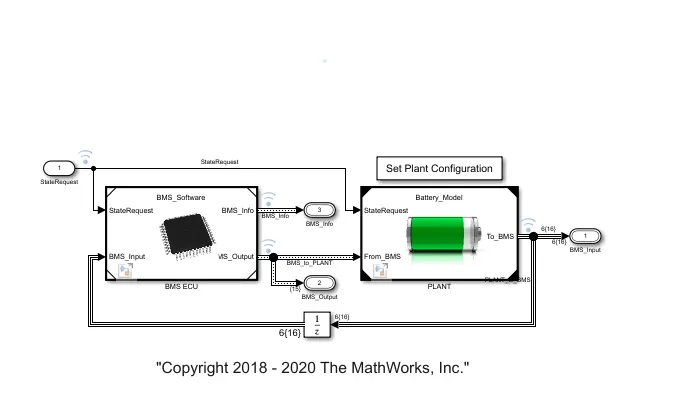
Explanation:
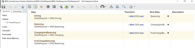
Test Case 1:Driving-Balancing-Charging-Balancing
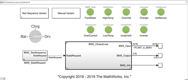
Result:
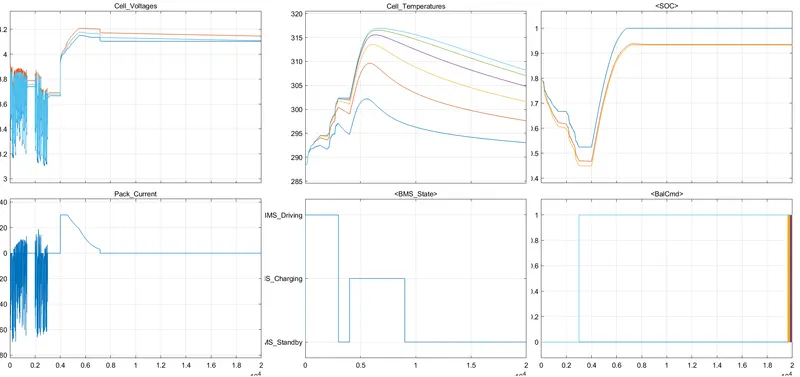 Graph 1 indicates the cell voltages of the all cells within the battery pack.Initally the vehicle is driving state,SOC drecases during this time peroid.After 3000 sec thenext step isbalancing which means the vehicle in standby condition.After another 1000 sec,the next step is charging phase and the battery reaches nearly 100%.At end the voltages lie between 4 and 4.2V.
Graph 2 represent the pack current and during charging phase its showns constant current.
Graph 3 showns the temperature of the battery pack.Its shows which cell temperature is high and low.The cell no 6 is hotter than cell no 1 because thermally insulated on one side and the degration of cell no 6 faster than cell no 1.Therefore active thermal management system is need to keep thermal differneces within few degree.
Graph 4 represent the stateRequest.
Graph 5 shown the SOC of the cells.Initally is nearly 80% and reaches 100% while charging.
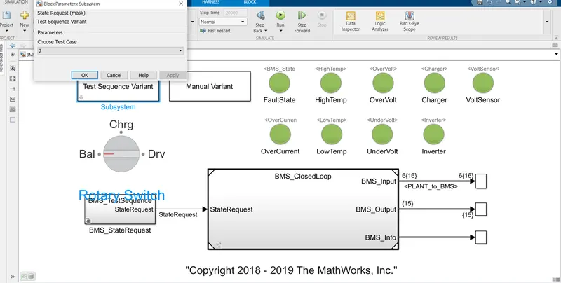
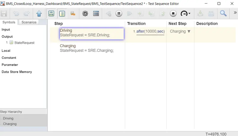
Test Case 2: Driving-Charging
Result:
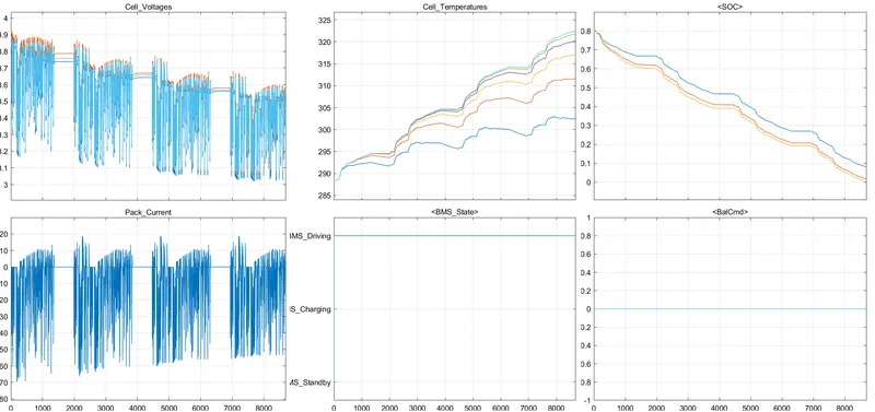
Graph 1 the voltage of all cells is deflecting in the same manner and decreases.It has 4 deflection parts has temperature increases.The cells whith initally 80% SOC decreases gradullay and reaches 0%,BMS State indicates the staterequest.
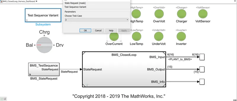
Test Case 3-Charging:
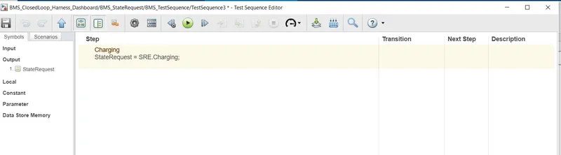
Result:
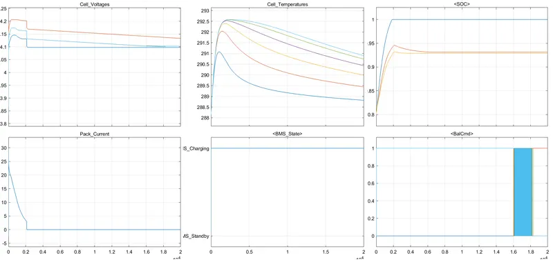
From the above graph,All the cells are initiated with at differnet voltages where the 6 the one havong the higher voltage of 4.2 V and 1st one haing of 4.1 V and remainig falling under this BMS range on the charging state.n the graph 3 the temperature increses for some amount of time and decreases.The SOC was 80% initial and reaches 100% as state request in the charging mode.
2)Aim:
To explain the Coulomb counting method and implementation of the method in the Battery management system.
Explanation:
In general, the SOC of a battery is defined as the ratio of its current capacity (`Q(t)`) to the nominal capacity (`Q_n`). The nominal capacity is given by the manufacturer and represents the maximum amount of charge that can be stored in the battery. The SOC can be defined as follows:
SOC(t)=`(Q(t))/Q_n`
The various mathematical methods of estimation are classified according to methodology.
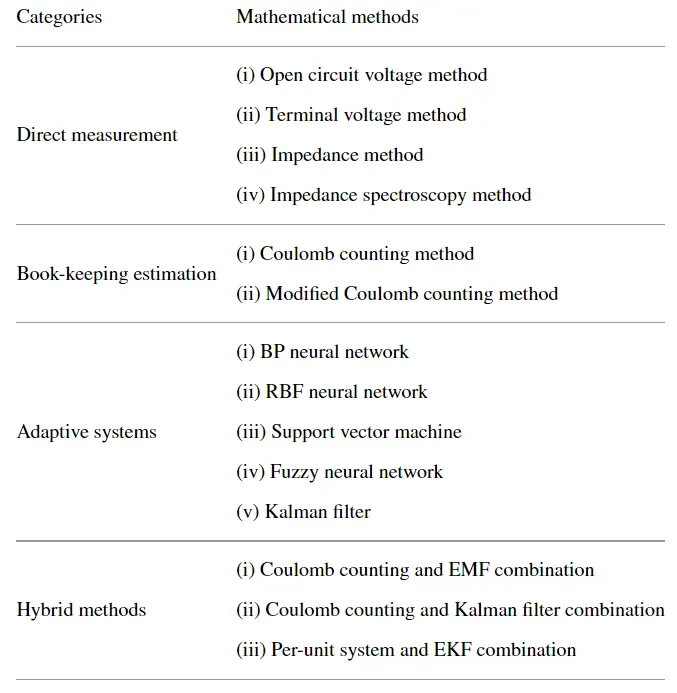
Book-Keeping Estimation:
Book-keeping estimation method uses battery discharging current data as input. This method permits to include some internal battery effects as self-discharge, capacity-loss and discharging efficiency. Two kinds of book-keeping estimation methods have been employed: The coulomb counting method and the modified Coulomb counting method.
Coulomb counting method:
The Coulomb counting method measures the discharging current of a battery and integrates the discharging current over time in order to estimate SOC. Coulomb counting method is done to estimate the SOC(t), which is estimated from the discharging current, I(t), and previously estimated SOC values, SOC(t-1). SOC is calculated by the following equation:
`SOC(t) = SOC(t-1) + ((I(t))/Q_n)* Delta(t)`
The factors that affect the accuracy of the Coulomb counting method include temperature, battery history, discharge current, and cycle life
BMS implements coulomb counting for SOC estimation:
The system does the estimation of SOC by the Coulomb counting method.The method is implemented inside the BMS ECU.
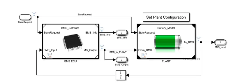
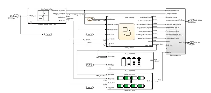
With the BMS ECU, the SOC estimation subsystem appears. In the SOC Estimation subsystem,the SOC is calculated using various methods.
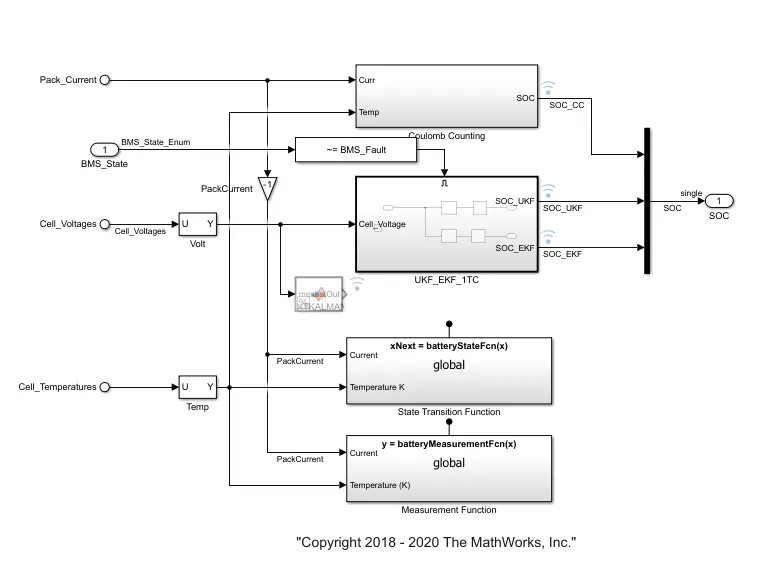
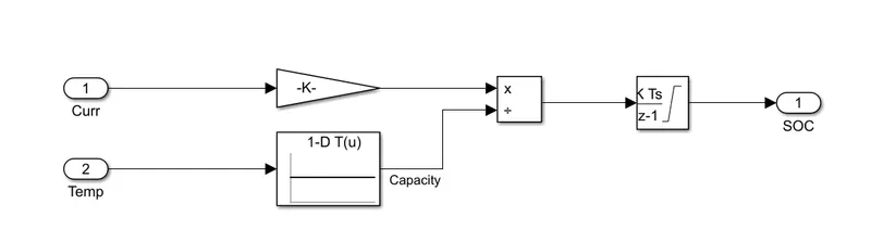
In the Coulomb Counting method, the temperature and Current from the plant model are given as input. The current signal given to gain block and temperature is given to lookup table, Depending upon the temperature, capacity is measured. The output of the gain and lookup table is divided and intergated with respect to time.
Conclusion:
Thus Battery Managmenet Algorithms model is simulated for differnet test cases and SOC calculation using the Coulomb counting method.