Week - 4
1)Aim:
To implement the control Logic for the washing Machine using Stateflow as per the given condition.
Condition:
- If the power supply is available, the system gets activated
- If the Water supply is not available, stop the process & indicate through LED
- Soaking time should be 200s followed by Washing time of 100s.
- Then rinsing happens for the next 20s & dryer runs for 50
Block required:
- Constant Block
- Chart
- Display
- Lamp
Model:
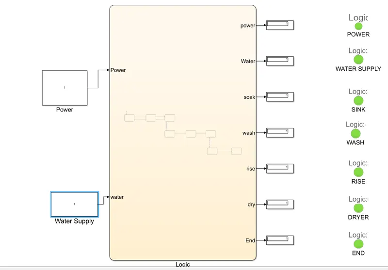
Control Logic:
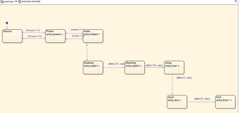
Explanation & result:
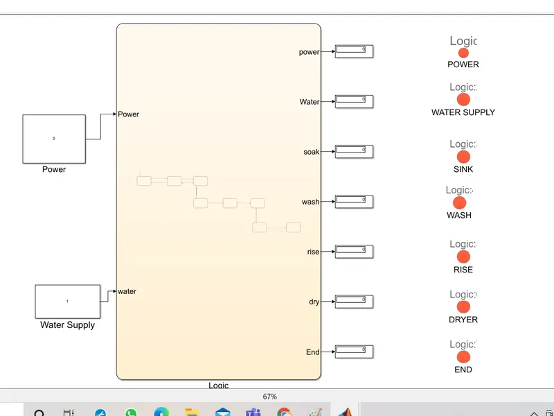
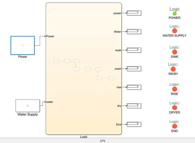
The power supply and water Supply Fed as input using constant block. When the power supply is not given or otherwise water supply is not present the process will not proceed and the corresponding lamp will blow.
In case of power supply is zero:
In case power supply is given but water supply is not present:
In Case of power supply and water supply is present;
Conclusion:
Thus the washing machine with a given set of conditions is implemented using a Stateflow (chart block).
2)AIM:
To implement gear logic as per given condition and display the result while running Simulation.
Condition:
Speed Range(kmph) Gear
0 to 15 1
16 to 25 2
26 to 40 3
41 to 60 4
Above 61 5
Blocks Required:
- Constant Block
- Chart Block
- Scope
- Display
Model:
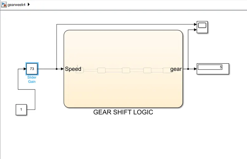
Control Logic:
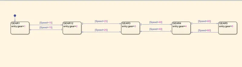
Explanation & Result:
To have varying input during Simulation,Slider Gain block is used. Slider gain is connected to control logic which will determine the output depending upon the speed.
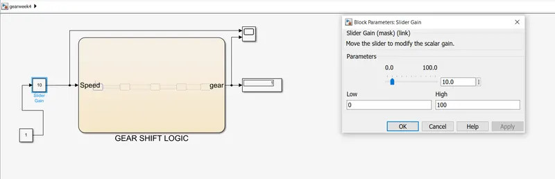
Given speed to the control logic is 10 kmph and gear displayed as 1.
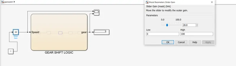
Given speed to the control logic is 28 kmph and gear displayed as 3.
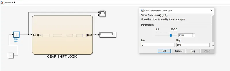
Given speed to the control logic is 73 kmph and gear displayed as 5.
likewise while changing the speed using slider gain,the gear will varies.
Conclusion:
Thus the gear logic is implemented and displayed during Simulation.