Week 6.2 - Setting up a model (Hanging Node)
JORGE LOZANO
Electronic Cooling Simulations using ANSYS ICEPAK
Setting up a model (Hanging Node)
A forced convection electronic simulation must be performed, generating postprocessing results from the simulation on a steady state condition.
Process
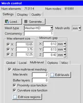
First the initial mesh generation must be performed, obtaining the preprocessing, and starting to develop according to the geometrical conditions as well as the defined complex geometries a local refinement and a skewness quality checkup for every iteration taken for the mesh.
- Inlet velocity 1 m/s at 20 C
- Heat transfer obtained: Conduction and convection, radiation neglected.
- External wall are closed boundary conditions except for the grills in the case
- Buoyancy effect is obtained where a natural convection happens.
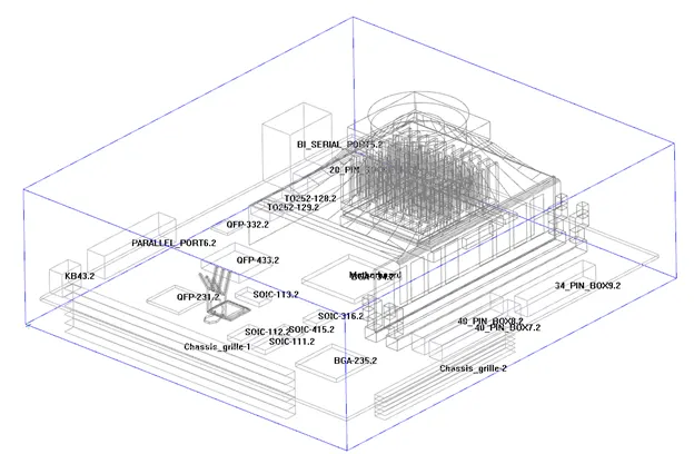
Once all elements and quality criteria is met, the following process is to select and determine the processing conditions for the simulation to operate on.
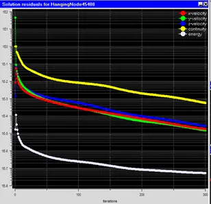
Having converged the mass, momentum and energy equation values, shows that the simulation in a general understanding is good to determine its final timestep to continue analyzing the case by the engineer.
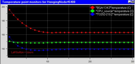
The temperature for several elements is recorded, and seen throughout the simulation, due to the nature of the simulation, is very important for this values to converge as well even after the general residuals convergence , obtaining a maximum of 163 C in the BGA-1342 element.
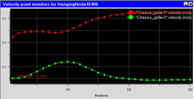
And velocity conditions are analyzed as well, seeing that the simulation has still more iterations to go for the case to obtain accurate results according to the preprocessing conditions.
Postprocessing
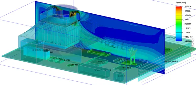
For the analysis part of the case, a volumetric flow is obtained seeing the velocity from the fan covering the area with the most heat transferred from the fan inlet, and the surface contour temperatures are obtained as well seeing the effect throughout the electronic board.
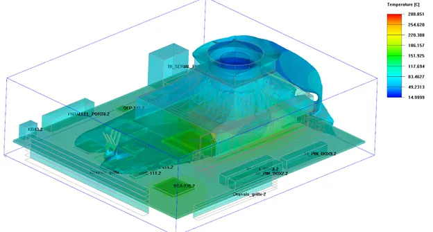
The following image shows the surface temperatures effects with a close to the heatsink under the fan and with the highest heat generation, reaching up to 288 C
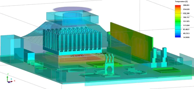
One of the main benefits from the CFD simulation is to analyze the flow distribution as well as the components organization to develop a great thermal comfort design from in this case an electronic case.
Conclusion
A CHT-CFD thermal electronic steady state simulation was performed, generating a postprocessing from the velocity and temperature plots, and contours obtained.