Week 5 - Rayleigh Taylor Instability
Challenge no- 5 Rayleigh Taylor Instability
Aim – The Aim is to understand the Rayleigh Taylor instability phenomena and how it takes place.
Objectives –
1. What are some practical CFD models that have been based on the mathematical analysis of Rayleigh Taylor waves? In your own words, explain how these mathematical models have been adapted for CFD calculations.
- Perform the Rayleigh Taylor instability simulation for 2 different mesh sizes with the base mesh being 0.5 mm. Compare the results by showing the animations (Attach them from your google drive). Observe the differences in the animation and explain the effect of mesh size on simulation. Also, explain why a steady-state approach might not be suitable for these types of simulation. [ Choose Air and Water for this simulation]
- Run one more simulation with water and user-defined material (density = 400 kg/m3, viscosity = 0.001 kg/m-s) for refined mesh.
- Define the Atwood Number. Find out the Atwood number for both the cases and explain how the variation in Atwood number in the above two cases affects the behaviour of the instability.
Rayleigh Taylor Instability –
01. It is a fluid instability phenomenon that occurs at the interfaces between two fluids of different densities when the denser fluid is positioned above the lighter one.
02. This mixing process is essential in various natural and engineering contexts, such as supernova explosions, oceanic circulation and inertial confinement explosions.
03. The instability arises due to the competition between the buoyancy force, which tends to drive the lighter fluid upward, and the inertial force, which tends to resist the motion. Understanding this interplay helps in predicting the behavior of fluid interfaces in different gravitational environments.
04. This phenomenon often leads to the transition from laminar to turbulent flow. This transition is crucial in many fluid systems as turbulence greatly affects transport processes such as mixing, heat transfer and mass transfer.
05. The growth rate of Rayleigh Tayor instability depends on the initial perturbation at the interfaces and the physical properties of the fluids involved. Studying these growth rates helps in quantifying the instability and predicting the time scales over which mixing occurs.
06. This phenomenon is essential in designing systems involving fluid interfaces, such as mixing devices, implosion driven devices.
Rayleigh-Benard Instability –
This instability occurs in a layer of fluid heated from below. When the temperature difference between the bottom and top of the fluid layer exceeds a critical value, convective cells from, leading to the transfer of heat through the fluid-by-fluid motion.
Kelvin-Helmholtz Instability –
This instability occurs at the interfaces between two fluids with different velocities. ‘
Richtmyer-Meshkov Instability –
This instability occurs at the interfaces between two fluids with different densities when they are impulsively accelerated.
Mathematical relevance of the instability model.
Reynolds-Averaged Navier Stokes Model – RANS model are widely used for simulating turbulent flow. They involve averaging the Navier Stokes equations over time to separate the mean flow from turbulent fluctuations.
Large Eddy Simulations – LES resolves large scale turbulent structures while modeling the effect of smaller scales. It is suitable for simulating flows with significant unsteadiness and large scale turbulent structures.
Detached Eddy Simulations – DES combines features of both RANS and LES. It uses RANS in regions where turbulence is week or attached to solid surfaces and transitions to LES in region with strong turbulence.
Multiphase Flow Models – CFD models for multiphase flow simulate the interaction between different fluid phase, such as gas-liquid, liquid-solid, or gas-solid flows.
Simulation: - Geometry Creation –
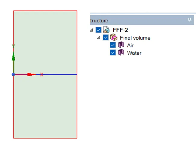
01. Create a square of size – 20 x 20 mm. Name it air.
02. Create another square above the existing square of same size, and name it water.
03. It means that, water which has higher density placed at the top and air which has lower density will be placed at bottom.
04. After geometry creation, use ‘PULL TOOL’ to create a surface out of the geometry.
05. Now club this geometry in to a common component.
Meshing –
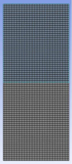
01. Mesh the 2D plain with the base line mesh & then refined the mesh with the required mesh size.
02. Name the entity as per the requirement.
03. Top entity should be named as per the material which has higher density.
04. Bottom entity should be named as per the material which has lower density.
05. Element quality is above 99%, as all the mesh are tetrahedral.
Setting Up Physics & Solution –
01. Go to setting up physics, and select the time simulation for the transient simulation. Where we can set up the time set up size.
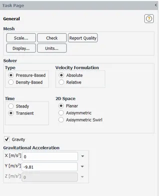
02. Take the gravity acceleration on account, with the gravity acting vertically downward in the ‘Y’ axis.
03. Gravity value is 9.81 m/s.
04. Choose ‘Laminar’ in the viscous model.
05. No need to enabling ‘Energy’ equation.
06. Material selection from the fluent data base.
a. Air with the default values.
b. Water as the default value.
07. Select multi-phase by volume. With ‘Implicit’ selection.
08. Define phase as air to the material air & water to the material water.
09. Initialize the simulation with ‘Standard Initialization’.
10. Create ‘Phase Contour’ & ‘Animation’ against the phase contour.
11. Patch the geometry with water & air. Patch water by fraction number-1 & air with – 0.
Case No -1 Simulation with the base line mesh.
01. Mesh Size – 0.002 Meter.
02. Time steps size – 0.0005 Sec.
03. Number of time steps – 350.
04. Total mesh count – 200
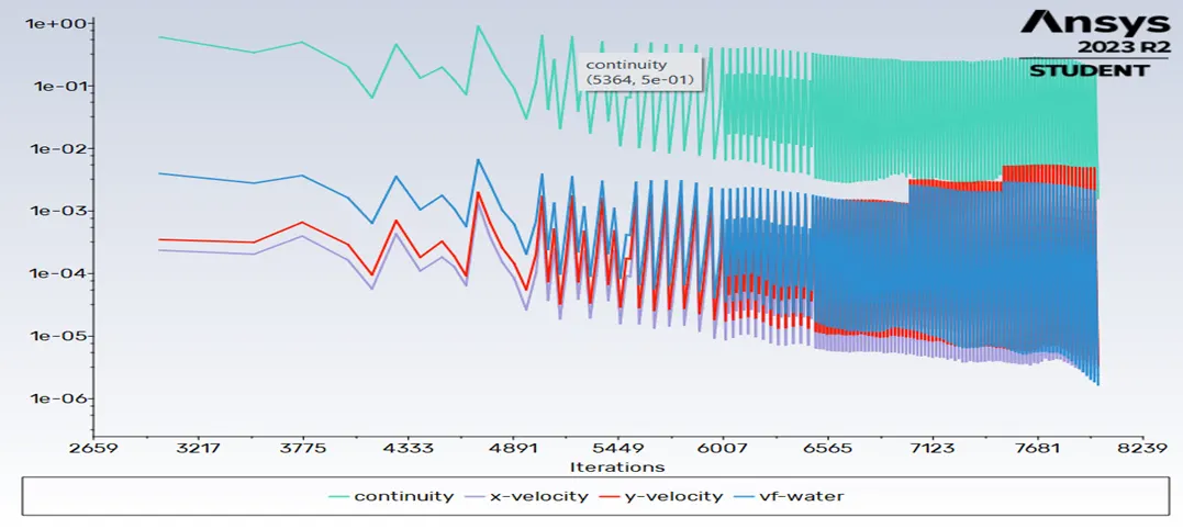
Case – 2 Refined Mesh
01. Mesh Size – 0.0002 Meter.
02. Time steps size – 0.0005 Sec.
03. Number of time steps – 400.
04. Total mesh count – 20000.
https://youtu.be/65R9h_eCNBI?si=l6m4GrSr5OlQxvI7
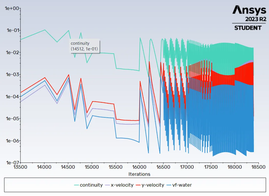
Case – 3 Refined mesh with user material.
01. Mesh Size – 0.0002 Meter.
02. Time steps size – 0.0005 Sec.
03. Number of time steps – 400.
Total mesh count – 20000
01. Material – Water & User Material
02. User material – (density = 400 kg/m3, viscosity = 0.001 kg/m-s)
https://youtu.be/ds99cZONMMo?si=R5ZRYOff8JLR5RYA
Observation –
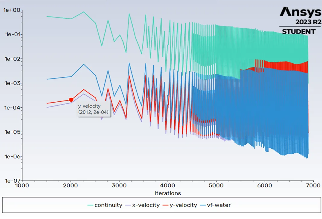
01. With higher mesh resolution, the solution become unstable and one has to reduce the time step size.
02. Finer mesh produces better flow pattern.
03. For the user defined material case, one must run the simulation for more numbers of iteration to settle down. There are more bubbles and spikes in the first case, when compared to the third case, because the density difference is less, there fore the Atwood number is low and the penetration is also low for the third case.
04. Steady state simulation gives the end result of the solution and we are interested in the intermediate solution as well, so transient solution id preferred.
Atwood Number –
The Atwood number is a dimensionless number in fluid dynamics that measure the relative density difference between two fluids.
Conclusion –
Atwood number is an important parameter in the study of Rayleigh-Taylor instability. In Rayleigh-Taylor instability, the penetration distance of heavy fluid bubble into the light fluid is a function of acceleration time scale. A . g. t^2.
Where G is the gravitational acceleration and t id the time.
Case -1 Atwood number – 0.9975
Case -2 Atwood number – 0.4278
There fore penetration distance to heavy bubble A . g . t^2 in case 1 would be higher as it is directly proportional to A (Atwood number).