2D meshing for Plastic components
AIM -
- For the given Plastic Bottle Cap model, check for the geometrical errors and take the mid surface by suitable mid surfacing techniques.
- PID and Thickness assignment has to be done for all the mid surfaces. Mesh the same with given element Quality criteria.
PROCEDURE -
1. Importing CAD Model -
- First step is to import/open the CAD model in ANSA and after opening the CAD model following the GUI of ANSA -
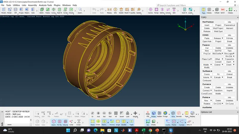
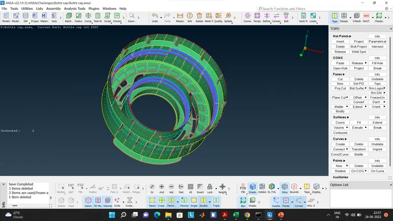
Figure 1 - CONS and Hotpoints are visible in the model
- The component broadly can be divided into -
- Main Body
- Threads
- Teeth
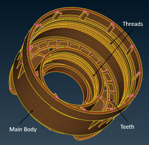
- After opening the CAD model, Faces > Orient option was selected to modify the orientation of the faces.
- Then we switched to the PID mode.
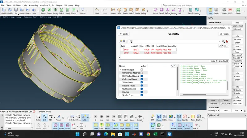
- Geometry checks - Using Checks > Geometry in the Tools tab we found some geometry errors after selecting the entire model which were autofixed using FIX option. Below is the snippet -
- After geometry errors free model, we go the Material tab (Ctrl + M) and do checks on in the materials tab.
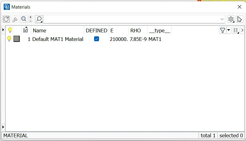
2.Mid Surface creation -
- Once the material is ON, now we go for the Mid Surface generation by segregating or hiding the parts
- Now we select Faces > Middle and then select the opposite faces to be Mid surfaced (MS).
- In some case we use Faces > Mid Surface and then select the faces.We also uncheck (X) the Delete original faces option before proceeding with the MS.
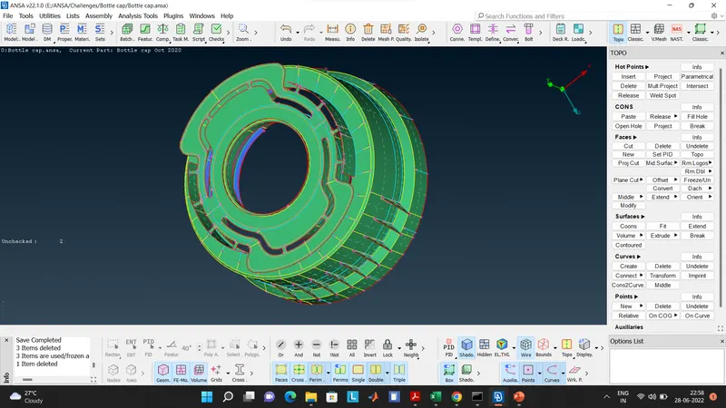
- It automatically detects the thickness of the PID part and recommends the Mid surface length. When we press OFFSET, the MS is created. Following are the snippets of the Mid Surfaced part -
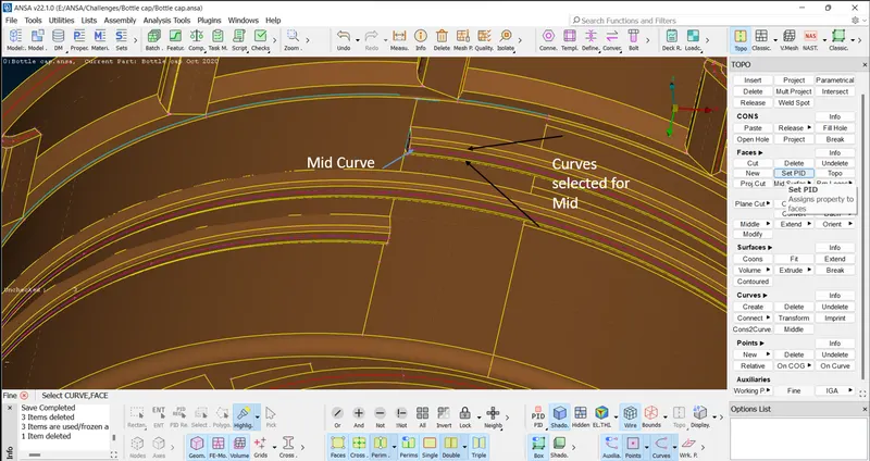
- For creating mid surfaces for thread portion we used Curve > Middle and then selected the curves as shown in the fig below.
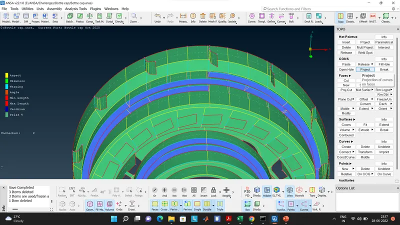
- We then projected the mid curve on the surface behind to create a face which will be the mid for the threaded area.
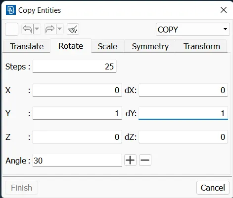
- Now, for the teeth area we first create mid for one of the teeth using Curve > Middle and then use Transform > Copy> Rotate option to create the mid for the rest of the teeths.
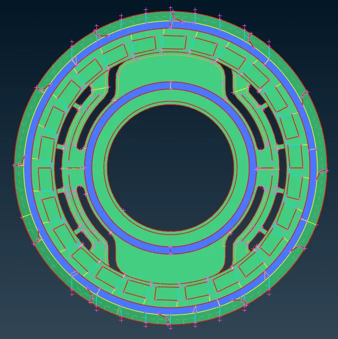
- In the below fig, teeths mid formation can be seen clearly.
3.Mid Surface Preparation for Meshing (Cleanup) -
- After creating Mid Surface, we now switch to Mesh module and then specify the element length (mm) between the nodes through Perimeters > Length and then selecting the Perimeters and Macros and inputing the value. Below is the snippet -
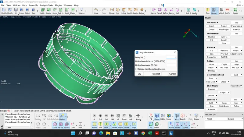
- Now need to perform some geometry clean up in which the parts are prepared for the meshing operation by deleting unnecessary fillets, curves and edges and also creating proper compartments structure (Division of part in various section) for proper meshing.
- Checking for even number of edges at the punched area using Perimeters > Number and then selecting the edges of the punched or cavity area. If number is Odd then, using Num+/- we can increase or decrease the edges as per requirement. In the below fig, the element number was 43 which need to be either increased or decreased to even number.
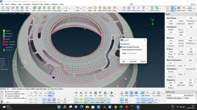
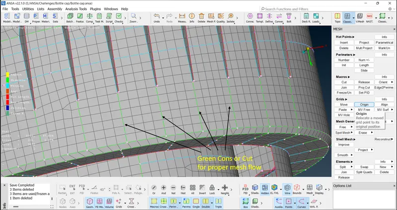
- Box type creation (Green cons) using Macros > Cut option can also been in below snippet which are created for proper mesh flow.
4.Quality Criteria and Meshing -
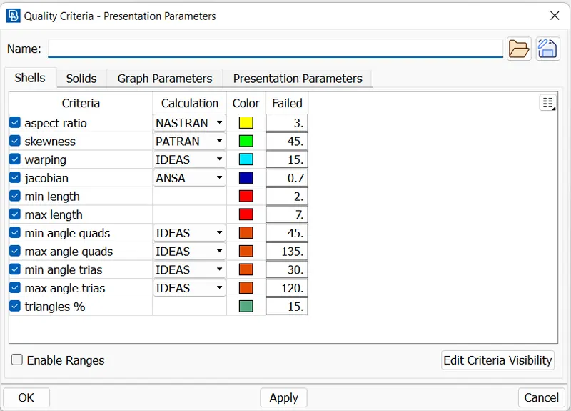
- We now fees Quality Criteria as per the requirement in the Quality Criteria tab which can be easily accessed with F11 function key. Below is the snippet -
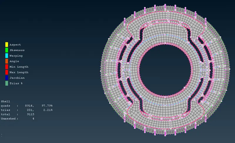
- We start with the bottom part as it has some complex design or curves and punch holes as well.
- For Meshing, we select Mesh Generation > Best Mesh option which automatically selects the best case scenario.
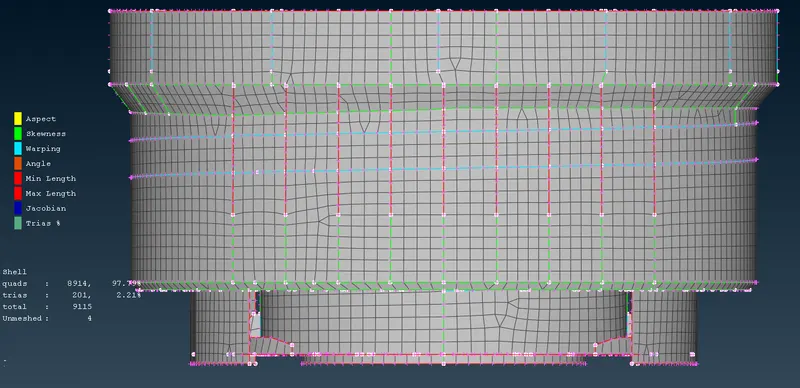
- Below are the snippets of the meshed parts -
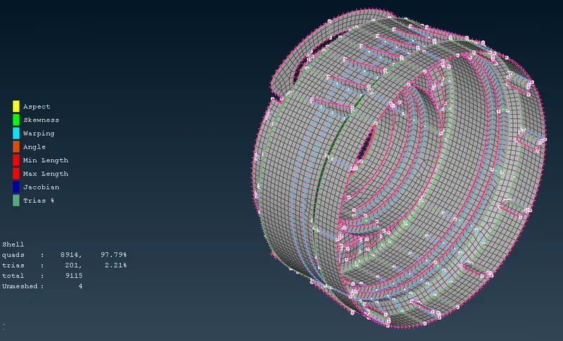
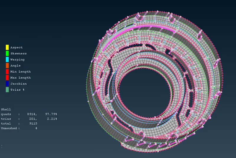
5.Meshing Improvement -
- In this step we try to improve the mesh flow and try to satisfy the quality criteria by eliminating trias near free edges or holes or on the fillets, opposite trias, rotating quads.
- Below are snippets of some issues which were resolved -
Case I - Removing Trias near free edge
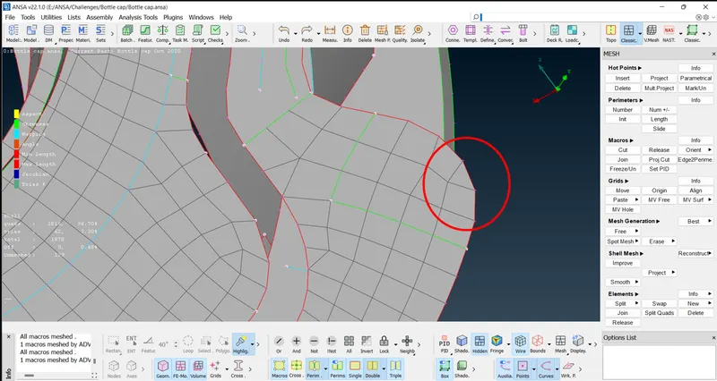
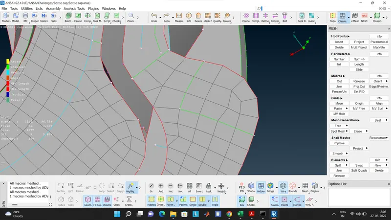
Steps used to resolve the issue -
- First we tried Reconstruction/Improve mesh option to improve the mesh. When not resolved then we opted for different approach.
- We then isolated the area which needs to be worked on by using Edge2Perimeter option then with the help of Split/Swap/Join we eliminated the trias near the free edge.
- With the help of Smooth option we then smoothed the mesh in the macro area isolated.
- After Smooth option, we then connected the isolated area to the main part with the help of Join (Macros) option.
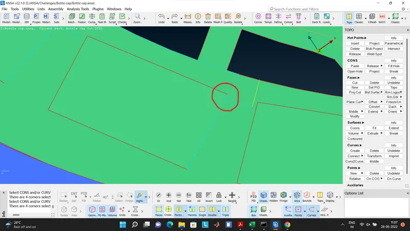
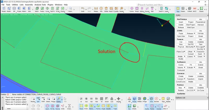
Case II - To avoid meshing error
- The teeth which were very near to the Blue was creating an unecessary hot point and the mesh was failing for quality at that area. So to avoid the error, following adjustment was done as shown below.
- Remaining Quality criteria were resolved with the help of Reconstruction/Improve option.
- Hence,
- The Trias near to free edge or holes or on the fillets and the opposite trias are eliminated.
- OFF elements after giving quality criteria are zero.
6.Shell as Solid -
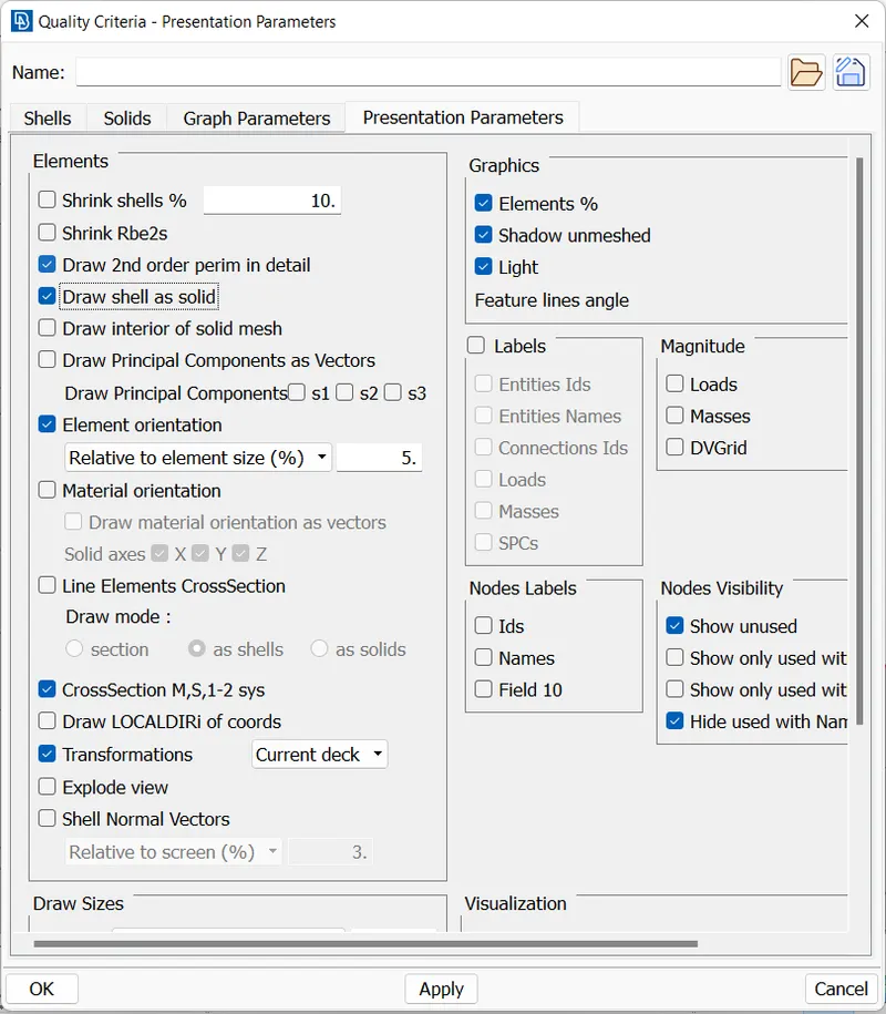
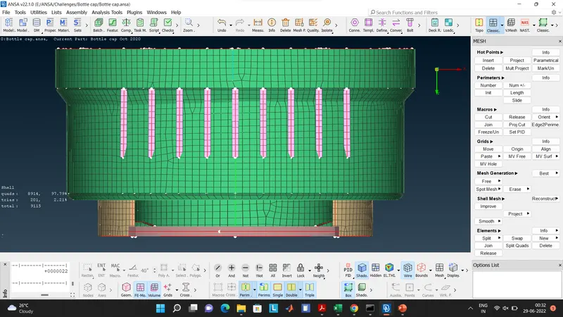
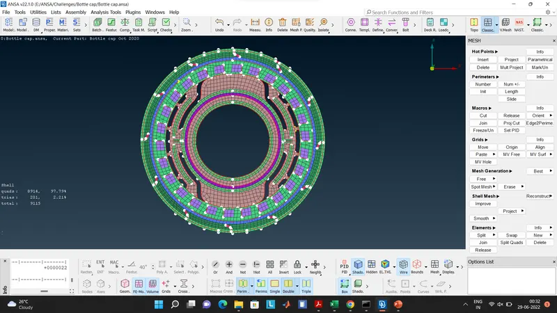
- We activated the Shell as Solid option from Quality Criteria > Presentation Parameters.
LEARNINGS -
These are some of my learnings after completing this challenge -
- Can successfully create mid surface for a object.
- Can perform geometry cleanup and prepare a surface for meshing.
- Can mesh the component and also improve the mesh taking into consideration the quality criteria recommended.
- Learnt proper use of Mouse control options.
- Creating PID for the elements.
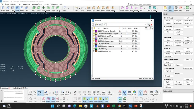
- Creating shell as solid and assigning thickness to the parts and then comparing it with parent geometry.
CONCLUSION -
- We have successfully Mid surfaced, Meshed the component and also complied with the Quality Criteria requirements.