Week -2
#PART 1 - SIMULATION OF DOORBELL
AIM -
- To make a Simulink model of Doorbell using solenoid block with the following details:
- In the arrangement, when the switch is closed the electromagnet will receive electrical power from the battery and pull the metal arm to hit the bell producing sound.
- To create a situation where the switch is closed for 2 seconds and then released.
- To observe the physical movement of the plunger.
MODEL-
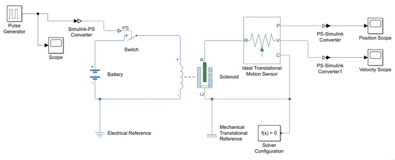 Figure 1
THEORY -
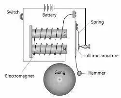
- A solenoid is a device comprised of a coil of wire, the housing and a moveable plunger (armature). When an electrical current is introduced, a magnetic field forms around the coil which draws the plunger in. More simply, a solenoid converts electrical energy into mechanical work.
- Solenoid will do the work of the electromagent and he movable plunger will do the work of the hammer on the gong.
MODEL EXPLAINATION -
- We are assuming the solenoid block to function as the Electromagent part of the doorbell. For the functioning of the doorbell, we need input signal or pulse which will be provided through pulse generator.
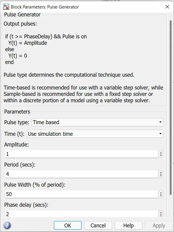
- As per our problem statement, we need to create a situation where the switch is closed for 2 seconds and then released. Therefore, we are considering cycle period of 4 seconds and phase delay of 2 seconds. The pulse width (% of period) therefore becomes 50%. Below is the configuration figure -
- The output of the pulse generator is in Simulink base which needs to converted to the Simscape base so we are connecting Simulink-PS converter at the output of the pulse generator and feeding it to the Switch.
- The electrical portion consists of Battery, Switch, Solenoid block and Electrical reference (for grounding purpose) which are connected as shown in the model above.
- The solenoid block consists connection terminals and a plunger which will behave as the gong for the doorbell. The plunger will remain activated when the pulse is generated for the period of 2 seconds and will be at rest for the rest of 2 seconds.
- Since the plunger is having a translatoinal motion, we need to provide Translational motion sensor which will measure or track the plunger position and velocity. The ouput of the solenoid block is given to the translational sensor. We have also provided Mechanical Translational reference block because we need some reference or datum with respect to which the plunger is translating.
- The output of the translational sensor which is in Simscape base needs to be converted back to Simulink base. So we have connected PS-Simulink converter at the P and V ports and connectd it to the scope blocks for reading purpose.
- We have used one Solver configuration block for solving and simulation purpose.
OUTPUT/PLOTS/RESULTS -
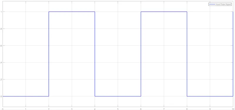
Figure 2 - Pulse signals generated by Pulse Generator
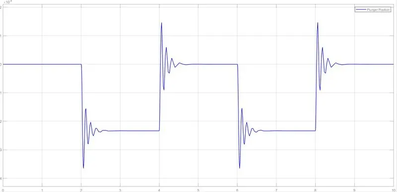
Figure 3 - Plunger position changes when pulse is generated
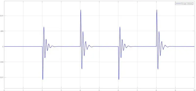
Figure 4 - Plunger velocity variation
#PART 2 - SIMULATION OF THERMISTOR TO TURN ON/OFF FAN
AIM -
- To make a thermistor to sense the temperature of a heater & turn on or turn off the fan as per the below conditions -
- Temperature source: 20 °C from 0 to 10 seconds, 27 °C from 10 to 30 seconds, 23 °C from 30 to 50 seconds.
- Fan conditions: ON if the temperature above 25 °C, OFF otherwise.
MODEL -
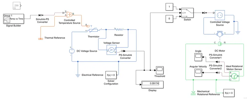
Figure 1
THEORY -
Thermistor -
-
A thermistor is a resistance thermometer, or a resistor whose resistance is dependent on temperature. The term is a combination of “thermal” and “resistor”. It is made of metallic oxides, pressed into a bead, disk, or cylindrical shape and then encapsulated with an impermeable material such as epoxy or glass.
-
There are two types of thermistors: Negative Temperature Coefficient (NTC) and Positive Temperature Coefficient (PTC). With an NTC thermistor, when the temperature increases, resistance decreases. Conversely, when temperature decreases, resistance increases. This type of thermistor is used the most.
-
A PTC thermistor works a little differently. When temperature increases, the resistance increases, and when temperature decreases, resistance decreases. This type of thermistor is generally used as a fuse.
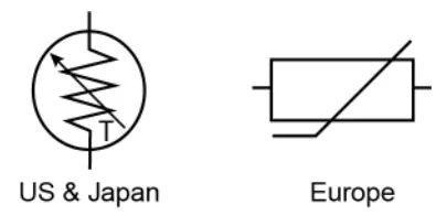
- Thermistor symbol is shown below -
DC Motor -
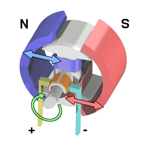
- A DC motor is any of a class of rotary electrical motors that converts direct current (DC) electrical energy into mechanical energy. The most common types rely on the forces produced by magnetic fields.
MODEL EXPLAINATION -
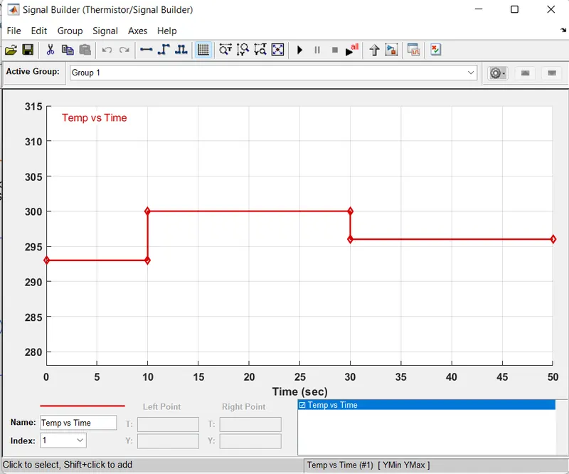
- The range of temperature is the input at the beginning, so we are using Signal builder block where we have given the inputs according to the problem statement.
- We have changed the time range to 0-50 seconds and given the temperature inputs in Kelvin in the signal builder block. 293 K from 0-10 sec, 300 K from 10-30 sec and 296 K from 30-50 sec. The signal builer block window is as below -
- The ouput of the signal builder is converted to Simscape base by using Simulink-PS converter as it is to be fed to the Controlled Temperature source as the input. This controlled temperature sorce represents an ideal energy source in a thermal network that can maintain a controlled temperature difference regardless of the heat flow rate.
- We have also connected the Temperature source block to Thermal reference block.Reference block represents a reference point in a thermal network where the temperature is equal to absolute zero.
- The output of the Controlled temperature source is fed to the Thermistor block. Thermistors are thermally sensitive resistors whose prime function is to exhibit a large, predictable and precise change in electrical resistance when subjected to a corresponding change in body temperature.
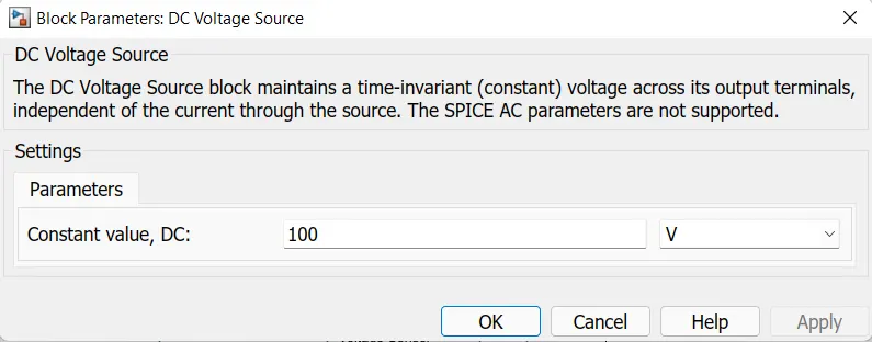
- The thermistor is being powered by a DC voltage source.We have assumed the value at the DC voltage source to be 100V. A resistor is connected in series to the thermistor and a voltage sensor is connected in parallel or across the resistor. By using Ohms law, V= IR, we can find the voltage value over the range of working temperature. Proper grounding is provided by using Electrical reference block.
- Now as we have condition of operating the fan above 25 Deg C (298 K), so we need to find voltage threshold value at temperature 298 K. Just for calculation purpose of threshold value, we replaced the signal builder block with a constant block giving input of 298 K and finding the threshold value at the scope. Below is the snippet -
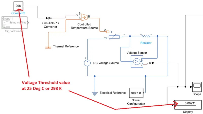
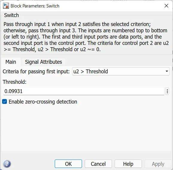
- The threshold value at 298 K comes out to be 0.09931 which will be used with if condition in the Switch block.
- Now we are using Switch block which has three inputs namely Port1, Port2 and Port3. Port2 is a control input where if the signal given to Port2 is satisfied with the condition and threshold of the switch block then it passes Port1 as output and if it is not satisfied then it will pass Port3 as output.
- So we have feeded the threshold value of 0.09931 in the switch block condition. Only if the value at the input of the switch block is above 0.09931, the signal will be passed through Port1 to the Controlled Voltage source block through Simulink-PS converter.
- Controlled Voltage source (CVS) block represents an ideal voltage source that is powerful enough to maintain the specified voltage at its output regardless of the current passing through it.
- As we are getting required output using the condition logic, now we are assuming a DC motor form electric library as a fan to implement the output logic. DC motor is an electromechanical block that takes an electrical input and provides mechanical rotational output. At the output of CVS we have connected DC motor and also have grounded the circuit using Electrical reference. Every time the condition is satisfied at the switch, there will be output available at the output of the DC motor.
- As we want to measure the angular velocity and change in angle at the output of the DC motor, therefore we have used Ideal Rotational motion sensor (IRMS) to measure and plot the same by using scope blocks by passing it through PS- Simulink converter.
- The circuit including DC motor, IRMS is connected to the Mechanical rotational reference block for rotational reference. Solver configuration block is also provided for solving and simulation purpose.
OUTPUT/PLOTS/RESULTS -
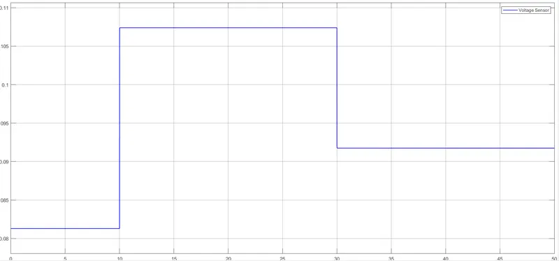
Figure 2 - Only during 10-30 seconds, the values are above threshold (0.09931). Rotation of fan is obtained only during this timeframe (10-30 seconds).
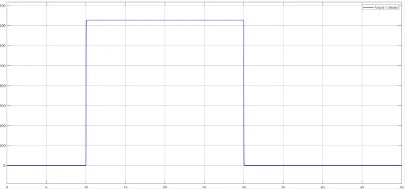
Figure 3 - Constant angular velocity is obtained during 10-30 seconds timeframe.
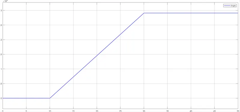
Figure 4 - Angle change during 10-30 seconds timeframe.
REFERENCES -