Week 6-Meshing of Hood Challenge
AIM -
- Meshing the hood as per criteria given below -
|
S.N |
Quality Criteria |
Value |
|
1 |
Aspect Ratio |
5 |
|
2 |
Skewness |
45 |
|
3 |
Warping |
15 |
|
4 |
Taper |
0.5 |
|
5 |
Min. Length |
2 Units |
|
6 |
Max. Length |
8 Units |
|
7 |
Min angle Quad |
45 |
|
8 |
Max angle Quad |
135 |
|
9 |
Min angle Tria |
20 |
|
10 |
Max angle Tria |
120 |
|
10 |
Tria % |
10 |
PROCEDURE –
1.IMPORTING THE MODEL
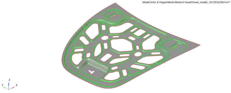
- First step basically is to import the model. As it is a .hm file so we simply import the file from the folder and below is the graphics area after importing -
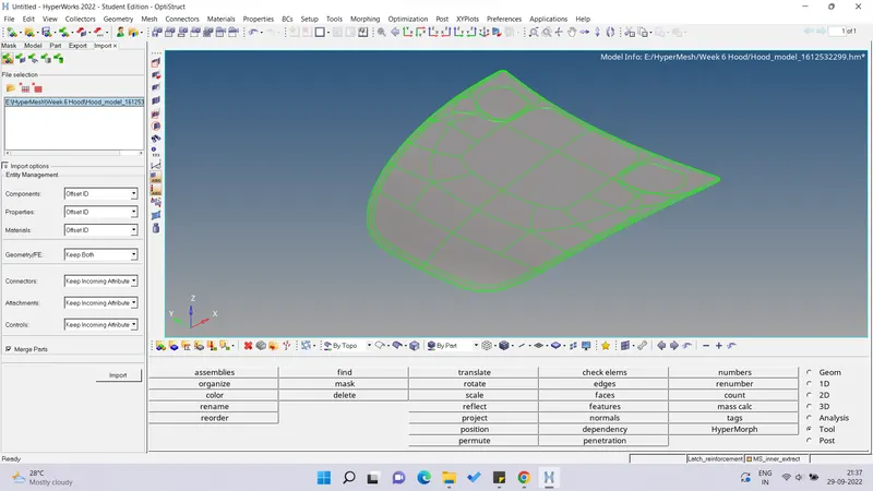
- After importing the file, we check for some free edges in wireframe mode and then toggle or patch the free edges to form continuity in the part.
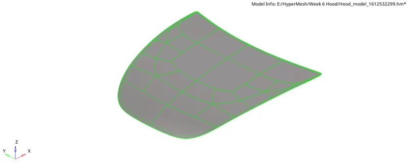
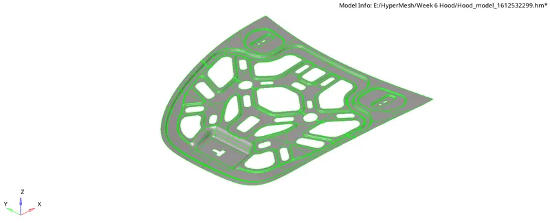
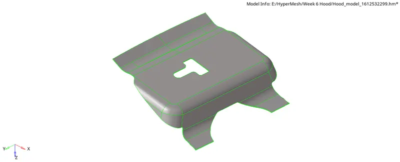
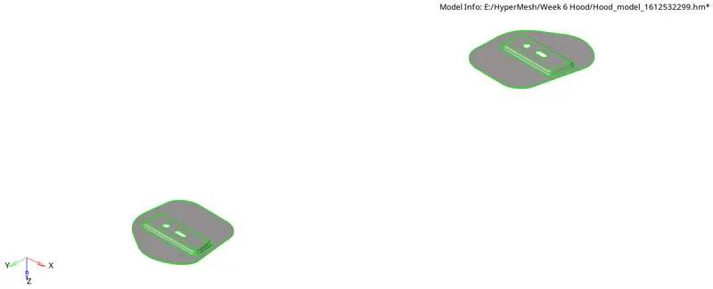
- There 4 parts in the model –
- Outer Extract
- Inner Extract
- Latch
- Hinge
- The snippet of the parts are as shown below –
2.MID SURFACE AND GEOMETRY CLEANUP
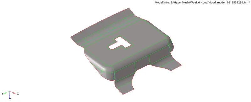
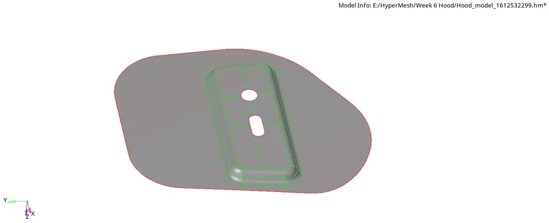
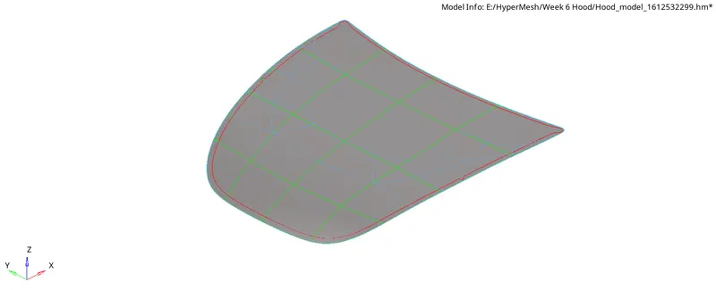
- After importing and performing removing some free edges we now are going to extract mid surface using Geom > Mid surface and selecting the extraction option as Offset + Planes + Sweeps for all the parts.
- The below snippets are of the mid surfaced parts in which the geometry clean-up is performed which means that all the unnecessary edges which might fail for minimum length criteria were toggled, washer splits were given to the hole area and the rectangle like sections were made for better mesh flow.
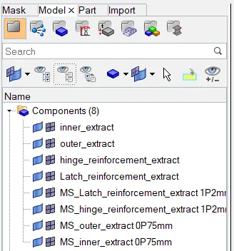
- Individual component card were created for the mid surface and same can be seen in the snippet below -
Defeaturing Outer Extract Hemming region –
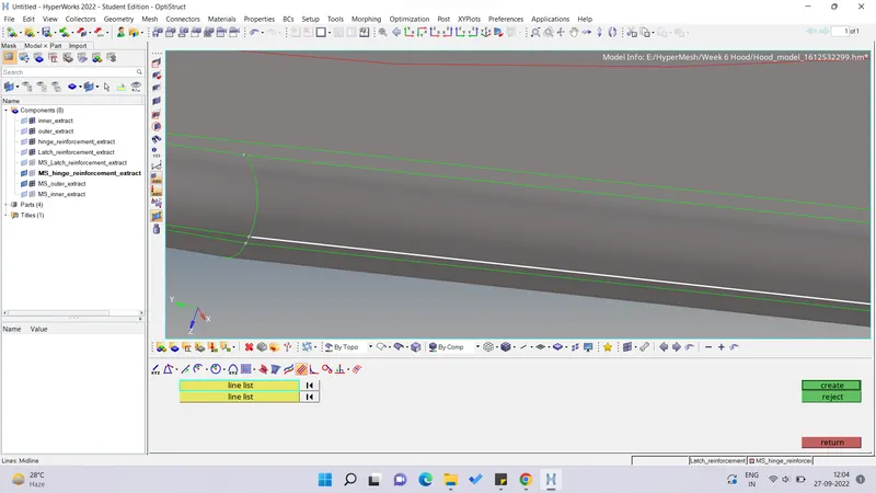
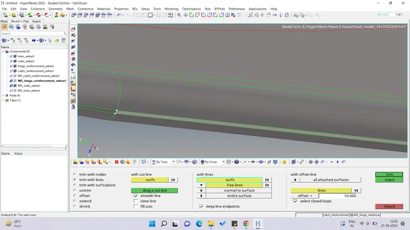
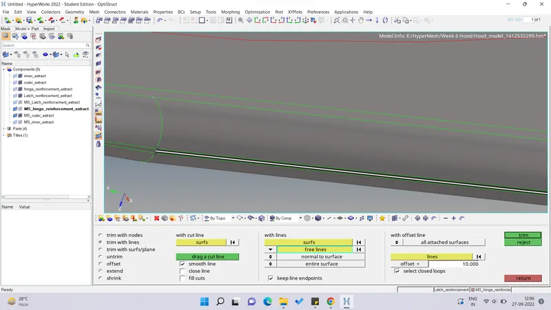
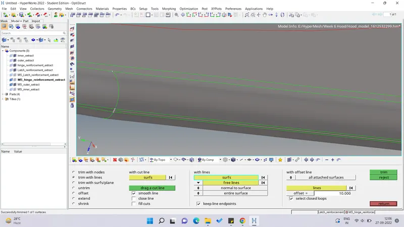
- The hemming region if kept as it is, will fail for minimum length criteria and thus we need to toggle the split lines and create mid lines using Geom > Lines > Midline and then select the two fillet edges to create midline.
- In the line list, we select the lines as shown below –
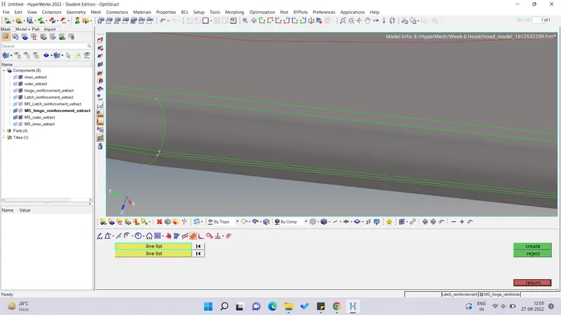
- Now the midline is created which just behind the surface on which we want to project it as shown below –
- Now we select Surface Edit > Trim with line and then select the surface which needs to be trimmed and then select the midline which will trim the surface as shown below –
3.MESHING AND QUALITY CRITERIA
- Now we start the meshing with the individual parts in which we start from the uppermost portion of the part and move downwards which resembles like flowing of a river for proper mesh flow and mesh direction.
- Before starting with the meshing, we input the quality criteria in the Criteria file setting in the Preference section tab.
- We select Automesh in the 2D section and then input the mesh size as 5 mm and then select mixed mesh for the surface to be meshed. We start with Latch part and following is the result after meshing –
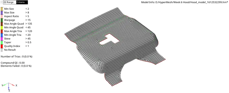
- The quality criteria can be seen in the left side of the image above.
- For better visualization of the model we have selected Geometry colour mode as By Topo and the Element colour mode as By Element Quality.

- Now we mesh the Hinge part and below is the result –
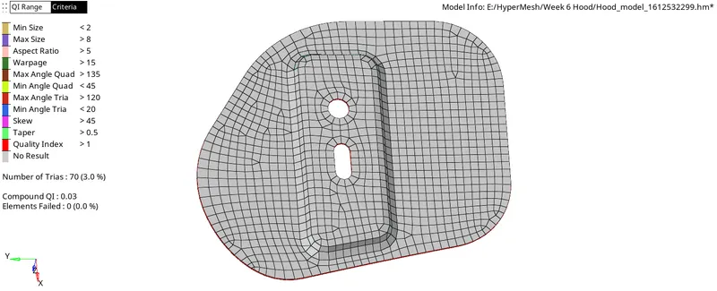
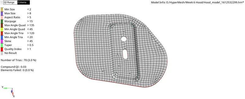
- Now the Inner and the outer extract are kind of symmetrical so we don’t have mesh the entire part. We just have to mesh the half part and then reflect the mesh on the other side and perform equivalence.
- Now we will mesh one half of inner extract and following the snippet after meshing –
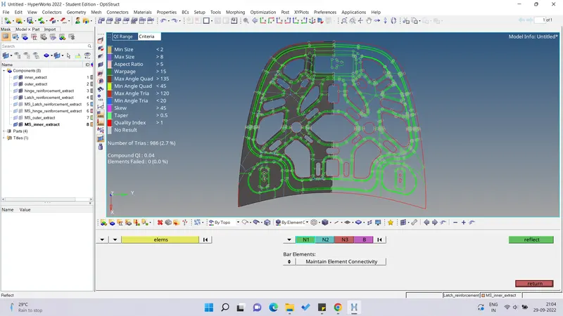
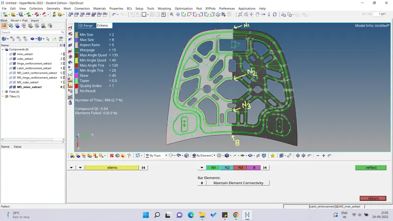
- One side of the mesh is as shown in the above image, the mesh needs to be reflected by using Tools > Reflect we select all the Displayed Elements and then Duplicate the elements. Now we select the N1, N2, N3 and B and then select Maintain element connectivity in the Bar elements section. Below is the snippet –
- Now after reflecting, we need to check for equivalence in the Tools > Edges section and we select the Displayed elements and select Preview equivalence and following is the result –
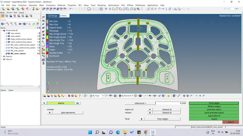
- After equivalence, following is the snippet –
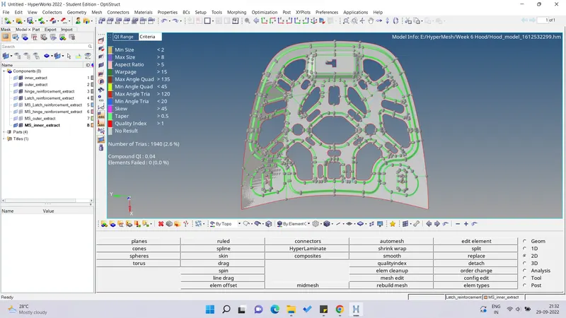
- The meshing for the outer extract and the reflects is shown in the below snippet –
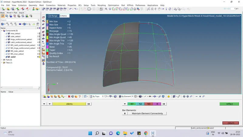
- One side of the mesh is as shown in the above image, the mesh needs to be reflected by using Tools > Reflect we select all the Displayed Elements and then Duplicate the elements. Now we select the N1, N2, N3 and B and then select Maintain element connectivity in the Bar elements section. Below is the snippet –
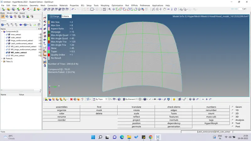
- Now after reflecting, we need to check for equivalence in the Tools > Edges section and we select the Displayed elements and select Preview equivalence and following is the result –
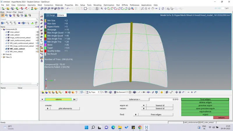
- Now we press equivalence and the edges get connected and below is the snippet –
4. CLEARING QUALITY ISSUES
- There were quality issues which emerged after meshing the model which were resolved using various options like Quality Index, Translate, Elem cleanup etc. Some of the issues and their resolution are shown below -
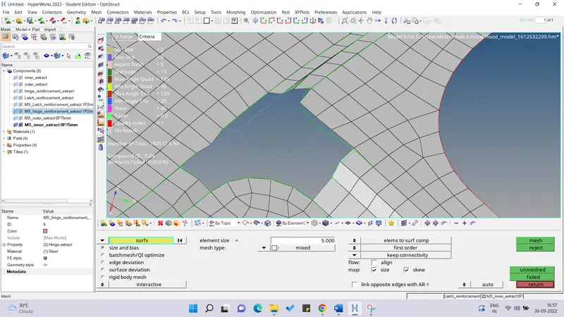
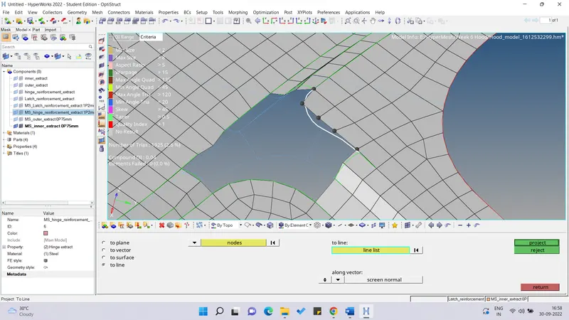
a. Nodes out of the geometry line
- The nodes were out of the geometry line which were made inline with the geometry using Project Panel then selecting the nodes and the line on which the nodes are to be projected. Below are snippet of before and after respectively -
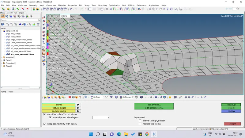
b. Warpage errors in the curved area
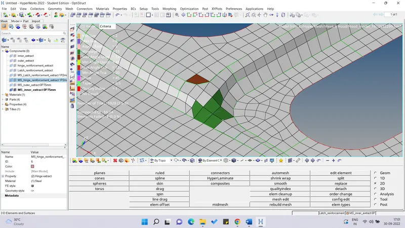
- In the curved area, the warpage erroers were spotted and thus resolved by using Elem cleanup option and then selecting the failed elements and then selecting the anchored nodes which resolves the issue as shown below -
- After performing element cleanup below is the snippet -
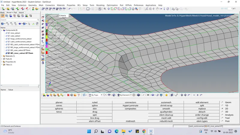
- Remaining errors were resolved using rebuild mesh, element optimize, splitting the elements, placing the node and remesh options.
5. ASSIGNING PROPERTY AND THICKNESS
- To begin with, we first create material and then select the predefined values for the material.
- Now we create 4 different property card for each part in the model. In the property card we select the material which we have defined in the above step, select card image as PSHELL and then assign the thickness based on the dimension of the parent geometry. The material and the property card can be seen in the snippet below -
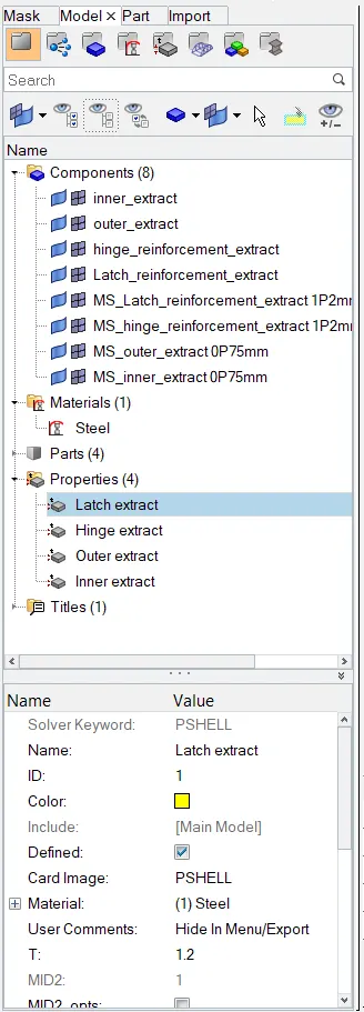
- The thickness to the mid surface gets visualized once we assign the property to the mid surface component created.
- The thickness can be seen in the mid surface once we select the 2D detailed element representation in the Visualization tab. Below is the snippet after enabling the option -
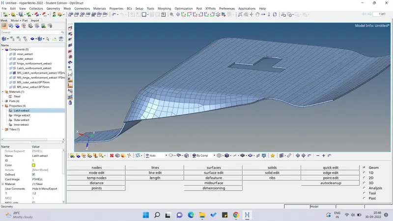
- In the above image we can see the latch part mesh with thickness enabled and the property card can also be seen in the left side mentioning the thickness based on the parent geometry.
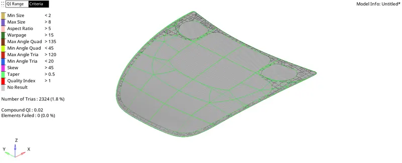
- After correcting all the issues and assigning all the property card to individual parts, following is the snippet of the model -
LEARNINGS-
- This challenge has taught me lot of new options which i used in clearing the quality issues and will also help in the future challenges.