System Level Simulation of ATV
AIM -
-
To carry out a system-level simulation of an all-terrain vehicle.
-
To prepare a technical report explaining the model properties & comments on the results.
WHAT IS BAJA SAE -
- Baja SAE challenges engineering students to design and build an off-road vehicle that will survive the severe punishment of rough terrain and in some competitions, water. As in real work situations, these future engineers work together as a team to discover and resolve technical challenges in design, test, and manufacturing, as well as business issues. The most rugged of all the competitions, Baja SAE also gives students the first-hand challenge of pursuing their passion while managing real-life demands and priorities. Each team's goal is to design and build a prototype of an all-weather, rugged, single-seat, off-road recreational vehicle intended for sale to the nonprofessional weekend off-road enthusiast.
THEORY AND SOME MAJOR BLOCKS USED IN MODEL -
- All Terrain Vehicle
- An all-terrain vehicle (ATV) is defined as a motorized off-highway vehicle designed to travel on four low-pressure or non-pneumatic tires, having a seat designed to be straddled by the operator and handlebars for steering control.
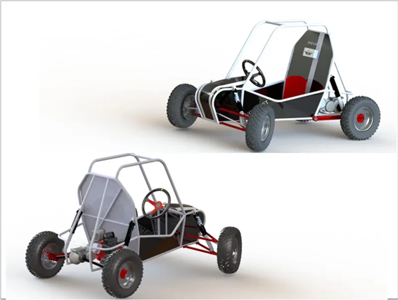
Figure 1 - BAJA ATV Structure
- Continuously Variable Transmission
-
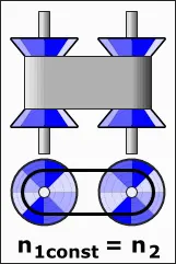
A continuously variable transmission (CVT) is an automatic transmission that can change seamlessly through a continuous range of gear ratios. This contrasts with other transmissions that provide a limited number of gear ratios in fixed steps. The flexibility of a CVT with suitable control may allow the engine to operate at a constant RPM while the vehicle moves at varying speeds.
-
CVTs are used in automobiles, tractors, motor scooters, snowmobiles, bicycles and earthmoving equipment.
-
The most common type of CVT uses two pulleys connected by a belt or chain; however, several other designs have also been used at times.
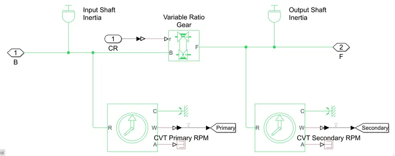
- The simulink model for the CVT is as shown below -
-
- Vehicle Body
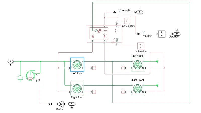
-
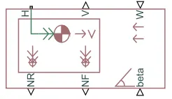
Represents a two-axle vehicle body in longitudinal motion. The block accounts for body mass, aerodynamic drag, road incline, and weight distribution between axles due to acceleration and road profile.
-
The vehicle can have the same or a different number of wheels on each axle. Optionally include pitch and suspension dynamics or additional variable mass and inertia. The vehicle does not move vertically relative to the ground.
-
Connection H is the mechanical translational conserving port associated with the horizontal motion of the vehicle body. The resulting traction motion developed by tires should be connected to this port.
-
Connections V, NF, and NR are physical signal output ports for vehicle velocity and front and rear normal wheel forces, respectively. Wheel forces are considered positive if acting downwards.
-
Connections W and beta are physical signal input ports corresponding to headwind speed and road inclination angle, respectively. If variable mass is modeled, the physical signal input ports CG and M are exposed.
-
CG accepts a two- element vector representing the x and y distance offsets from vehicle CG to additional load mass CG. M represents the additional mass. If both variable mass and pitch dynamics are included, the physical signal port J accepts the inertia of the additional mass about its own CG.
- Vehicle body connected to tire blocks is also shown in the above snippet.
-
- Lookup Table
- A lookup table is an array of data that maps input values to output values, thereby approximating a mathematical function. Given a set of input values, a lookup operation retrieves the corresponding output values from the table. If the lookup table does not explicitly define the input values, Simulink can estimate an output value using interpolation, extrapolation, or rounding, where:
-
An interpolation is a process for estimating values that lie between known data points.
-
An extrapolation is a process for estimating values that lie beyond the range of known data points.
-
A rounding is a process for approximating a value by altering its digits according to a known rule.
-
- A lookup table is an array of data that maps input values to output values, thereby approximating a mathematical function. Given a set of input values, a lookup operation retrieves the corresponding output values from the table. If the lookup table does not explicitly define the input values, Simulink can estimate an output value using interpolation, extrapolation, or rounding, where:
- Tire Model
- The Tire (Magic Formula) block models the tire as a rigid wheel-tire combination in contact with the road and subject to slip. When torque is applied to the wheel axle, the tire pushes on the ground (while subject to contact friction) and transfers the resulting reaction as a force back on the wheel. This action pushes the wheel forward or backward. If you include the optional tire compliance, the tire also flexibly deforms under load.
- The figure shows the forces acting on the tire. The table defines the tire model variables.
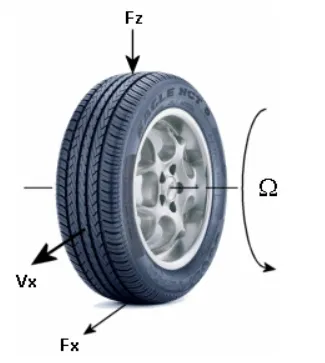 where, Fz = Vertical load on tire, Fx =Longitudinal force exerted on the tire at contact point, Vx =Wheel hub longitudinal velocity, Ω = Wheel Angular Velocity
- Generic Engine
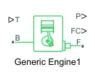
- The Generic Engine block represents a general internal combustion engine.
- This block is a suitable generic engine for spark-ignition and diesel. Speed-power and speed-torque parameterizations are provided.
- A throttle physical signal input specifies the normalized engine torque.
- Optional dynamic parameters include crankshaft inertia and response time lag. A physical signal port outputs the engine fuel consumption rate based on the fuel consumption model that you choose.
- Optional speed and redline controllers prevent engine stall and enable cruise control.
##MODELS FOR STUDY -
#CASE 1 - BAJA ATV WITH CONTINUOUSLY VARIABLE TRANSMISSION
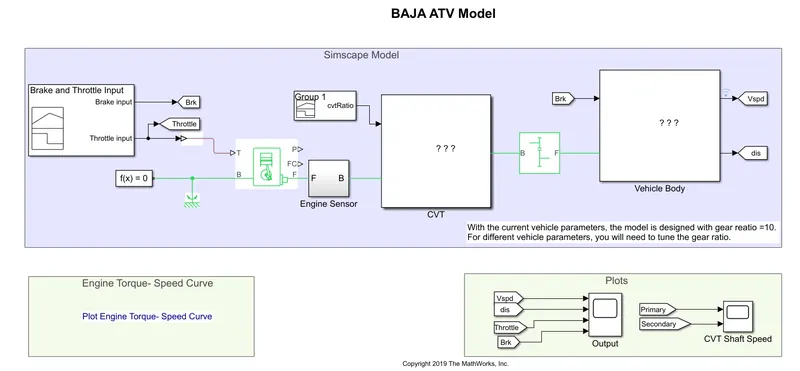
Figure 1a - Baja ATV with CVT model
MODEL EXPLAINATION -
- The mechanism by which power is transmitted from an engine to the axle in a Vehicle is Transmission. Transmission is very important system to run vehicles.
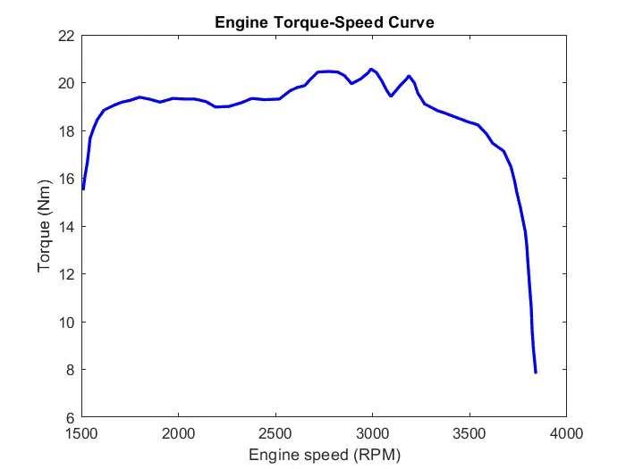
- Transmission consists of Engine – CVT – Gearbox – axle Shaft – Wheels. CVT and Gearbox combinedly gives the power reduction ratios of engine to get the required amount of speed and torque. The torque-speed curve relation for BAJA engine is plotted and taken as input. Below is the curve -
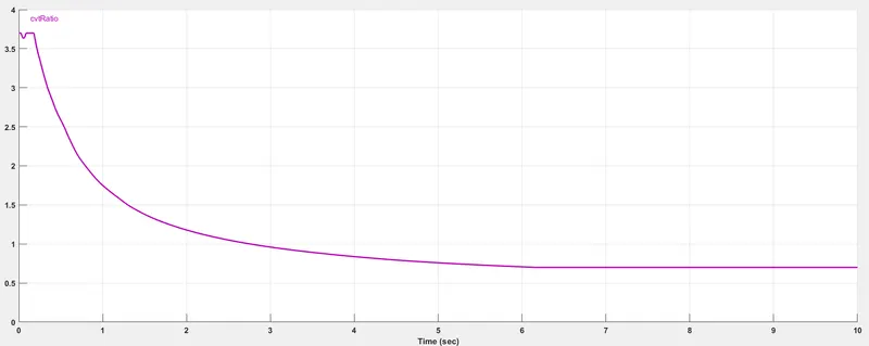
- CVT means Continuous Variable Transmission, it gives the variable amount of reduction ratio in between 0.4 to 3.1 which reduces the engine speed. CVT has fixed ratios as it can't be changed in standard CVT eg. CVTech. Therefore, Gearbox plays an important role in the transmission. The CVT ratio input is given through Signal builder block as shown below -
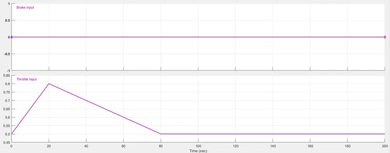
- To start with, we have inputted linearly increasing throttle input from 0.5 at 0 seconds to 0.8 at 20 seconds and then linearly decreasing from 0.8 to 0.5 at 80 seconds and then values are constant at 0.5 upto 200 seconds. Below is the Signal builder block giving throttle input -
- Parameters like Mass of vehicle body, Drag considerations are kept as default for this case. After all the steps the simulation is run and following are the output results.
MODEL OUTPUTS -
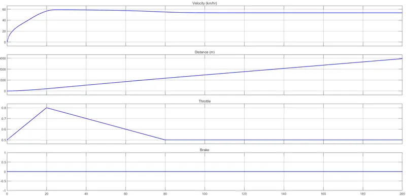
Figure 1b - Model Output plots (Velocity, Distance, Throttle, Brake)
- From the above Fig 2, we can decipher that from 0 to 20 seconds, when the throttle input is increasing the velocity is also increasing. Form 20 to 80 seconds, the throttle input is decreasing resulting in decreased velocity as well. For the time period 80 to 200 seconds, the throttle input is constant and hence there is no increase in velocity for that time period.
- Brake input is zero throughout and as the velocity is increasing wrt change in throttle input, the distance covered by the vehicle is also increasing.
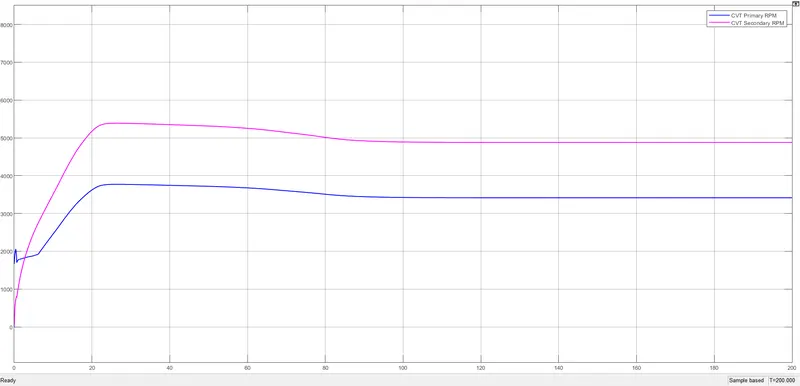
Figure 1c - CVT Secondary and Primary RPM
- From above Fig 3, we can decipher that at initial period the Primary CVT Rpm is more compared to the Secondary Rpm. But as the time perios increases, the Secondary CVT Rpm increases and becomes more than the Primary CVT Rpm. The reason behind this is because the Secondary CVT shaft is connected to the engine block.
#CASE 2 - BAJA ATV WITH CVT AND DASHBOARD
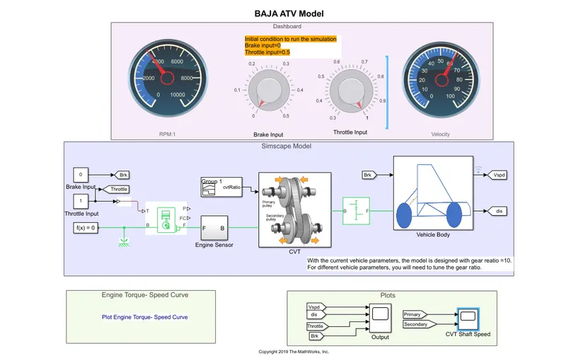
Figure 2a - ATV model with CVT and Dashboard
MODEL OUTPUT PLOTS -
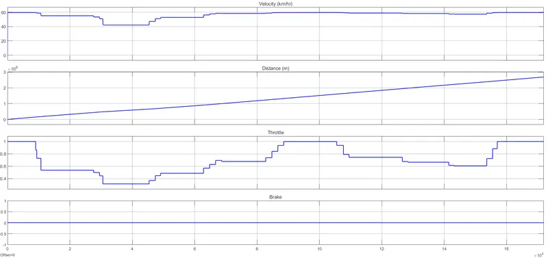
Figure 2b - This output plot is obtained after randomly rotating the throttle input knob.
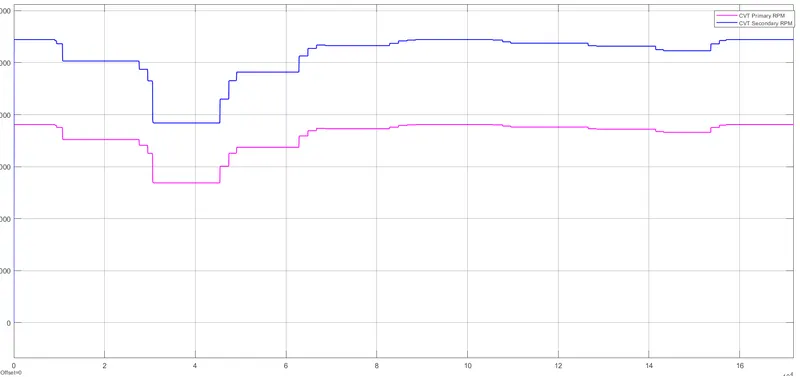
Figure 2c - Primary and Secondary CVT shaft RPM are moving in tandem. The secondary shaft rpm is greater than primary shaft rpm since the secondary is connected to the engine.
#CASE 3 - BAJA ATV WITH CVT ,DASHBOARD AND LOOKUP TABLE
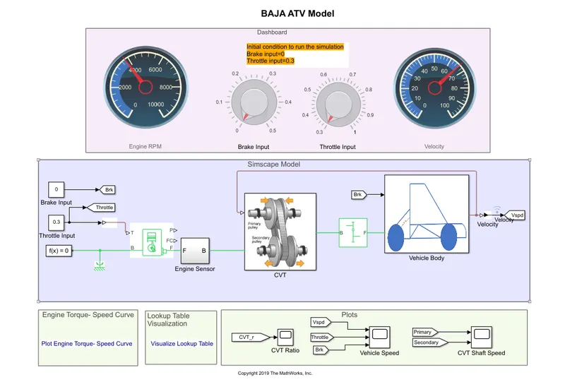
Figure 3a - ATV with CVT, Dashboard and Lookup table model
- The throttle and brake input in this model are not through Signal builder block, but are provided through rotating knob which are provided with the dashboard.
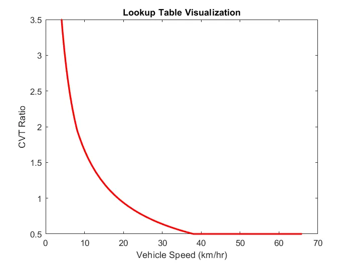
Figure 3b - Based on velocity of the vehicle which is taken as feed to the Lookup table for establshing relation between CVT ratio and vehicle speed can be seen in the above figure.
MODEL OUTPUT PLOTS -
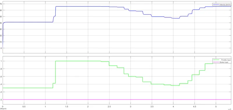
Figure 3c - Velocity variation when the throttle input is rotated randomly between 0.3 ad 1. Brake input is constant at zero.
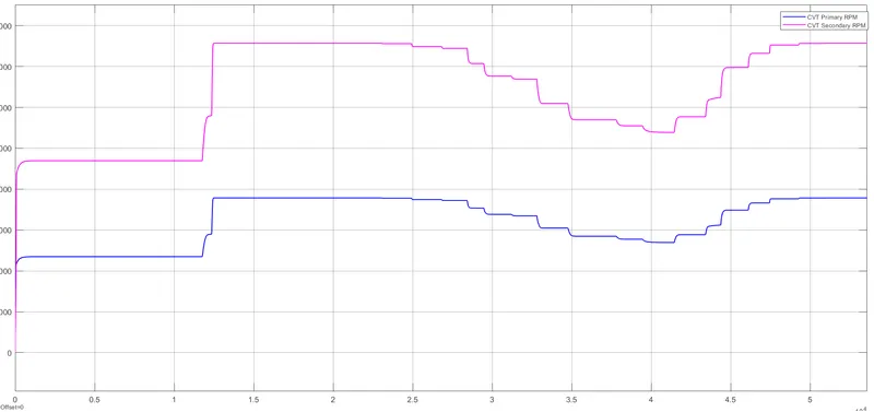
Figure 3d -Primary and Secondary CVT shaft RPM are moving in tandem. The secondary shaft rpm is greater than primary shaft rpm since the secondary is connected to the engine.
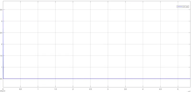
Figure 3e - CVT ratio variation over the cycle period
#CASE 4 - BAJA ATV WITH CVT AND LOOKUP TABLE WITHOUT DASHBOARD
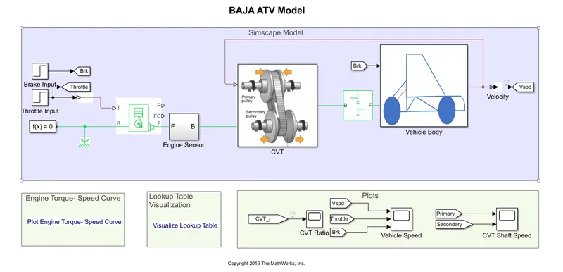
Figure 4a - ATV Model with CVT and Lookup table
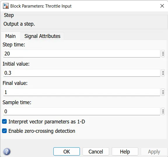
Figure 4b - Throttle input is given in the form of Step block. The initial value is 0.3 and the final value is 1 with a step time of 20.
The brake input is also fed by Step block with the initial and final values being zero.
MODEL OUTPUT PLOTS -
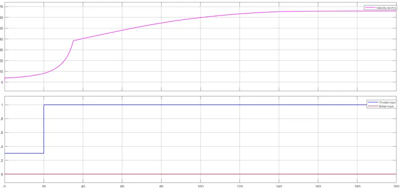
Figure 4c - Velocity variation with change in throttle input
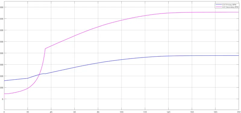
Figure 4d - In the initial period, the primary shaft rpm is greater than secondary shaft rpm. But after the step time of 20 seconds the secondary shaft rpm becomes greater than primary shaft rpm since the secondary shaft is connected to the engine.
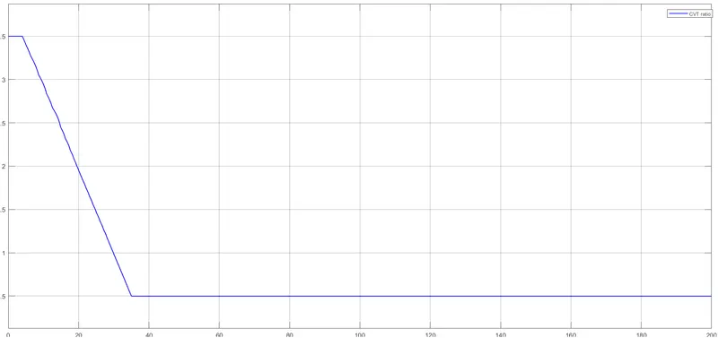
Figure 4e -CVT ratio varation
#CASE 5 - BAJA ATV WITH CVT WITHOUT DASHBOARD
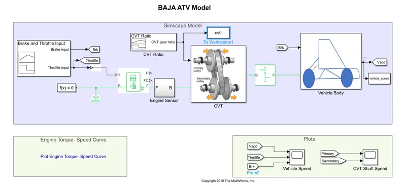
Figure 5a - ATV Model with CVT
- This case is similar to case 4, except that the throttle input, brake input and CVT ratio are provided by Signal builder block.
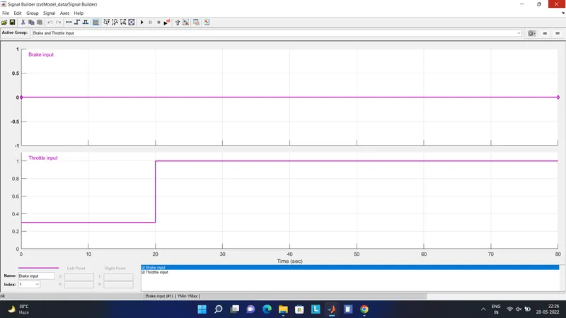
Figure 5b - Throttle input and Brake input through Signal builder block.
MODEL OUTPUT PLOTS -
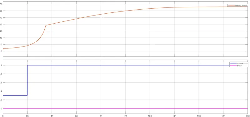
Figure 5c - Velocity varation based on throttle input.
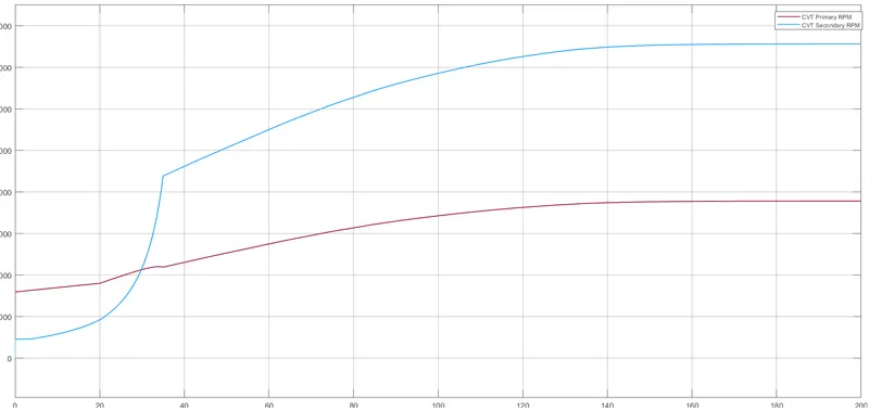
Figure 5d - CVT shaft rpm comparison which is similar to case 4.
Note - All the default values have been kept same and only the simulation has been run to get the output and for the study purpose.
REFERENCES -