Week 4-1D Element Creation Challenge
AIM -
1.Mesh the Given component with the Size of 5 Units.
2.Create 1D elements on the following component with given cross-section and DOF
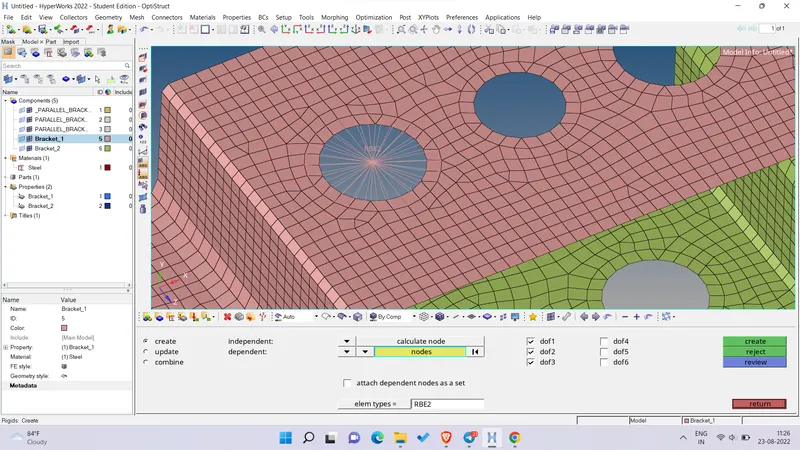
a. Rod element:- Translational DOF should be Constrained with RBE2 link
Cross-Section: BOX- Dimension a= 12 mm
dimension b=10 mm
Thickness t= 0.75 mm
b. Beam element:- All DOF should be constrained with RBE3 link
Cross-Section: I Section- Dimension a= 8 mm
Dimension b= 10 mm
Dimension c= 8.5 mm
Thickness t1= 0.75 mm
Thickness t2= .6 mm
Thickness t3= .6 mm
c. Bar element:- Constrain only x and y DOFs With RBE3 link
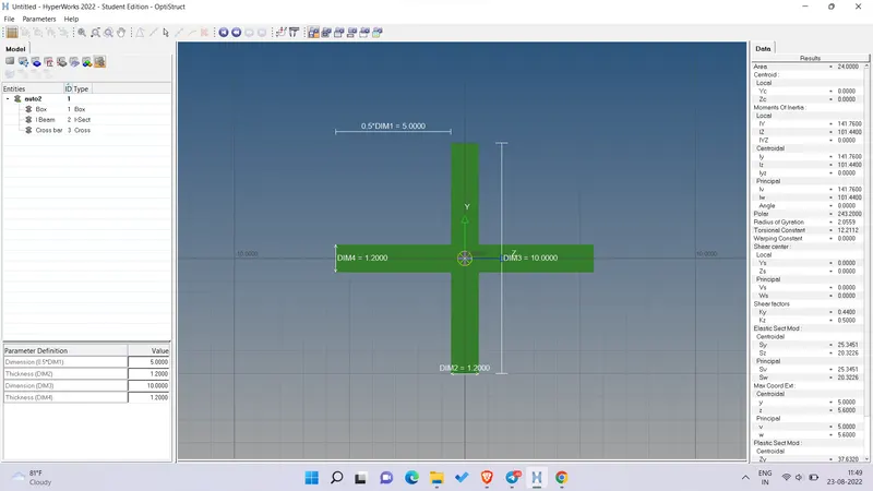
Cross-section: X section- Dimension DIM1= 5 mm
Thickness DIM2= 1.2 mm
Dimension DIM3= 10 mm
Thickness DIM4= 1.2mm
d. & e. Apply the mass of magnitude 10 with the RBE2 link
f. Join the two components with Spring elements
PROCEDURE -
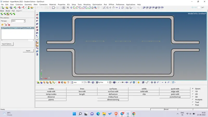
- First step is to import the model. As it is a IGES file, so we import using Import geometry option and then select the file format as IGES and select the file from the folder and import. Following is the graphics window after importing the model -
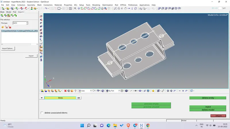
- Now there were some unnecessary lines in the model which were deleted using Delete > Lines > Displayed option.
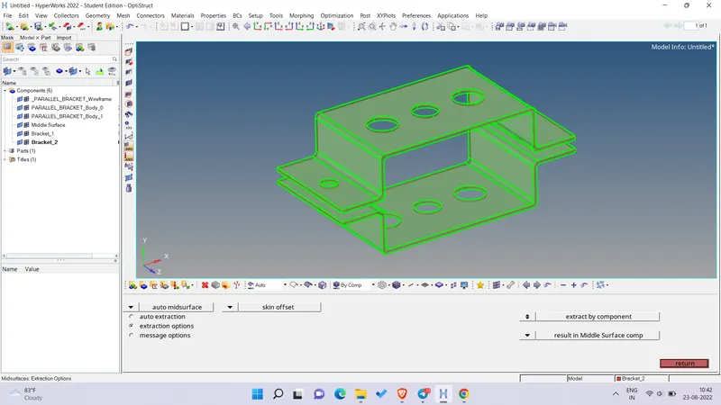
- As we have a proper model now, so we can proceed for mid surfacing. There are 4 options for mid surface extraction. But on comparing the results, the mid surface using Skin offset option was giving good results. Following is the mid surfaced model -
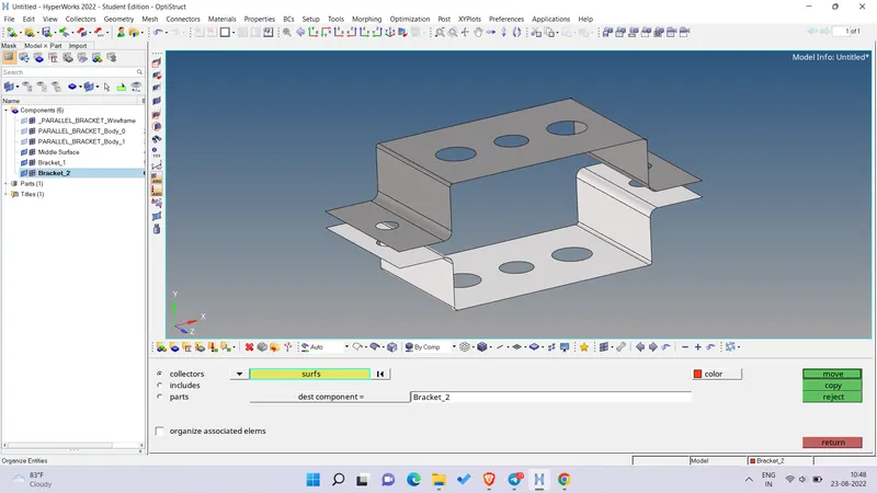
- We have created different components for the upper and lower mid surface namely Bracket_1 and Bracket_2 respectively. The mid surface component created automatically was deleted and the mid surface were moved to component Bracket_1 and Bracket_2 using Tool > Organize option.
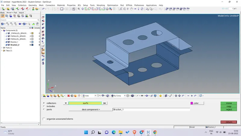
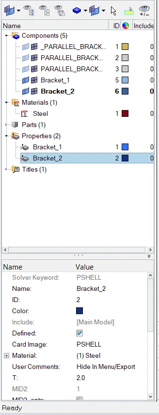
- Now we have created materials and properties for the components as shown in the snippet below
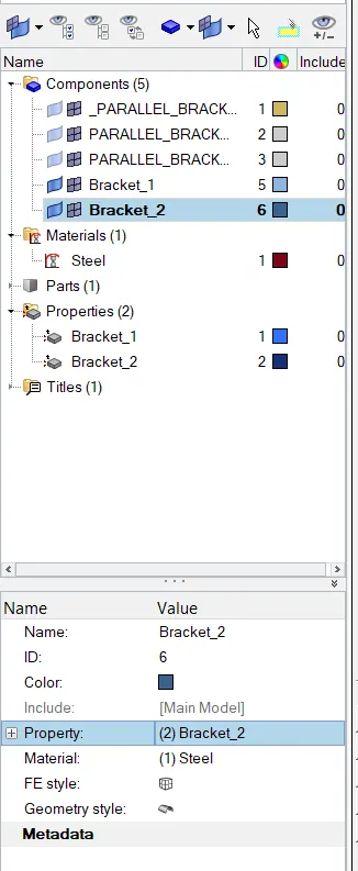
- After creating the material and the properties, we have assigned the material to the properties and then assign the properties to the component -
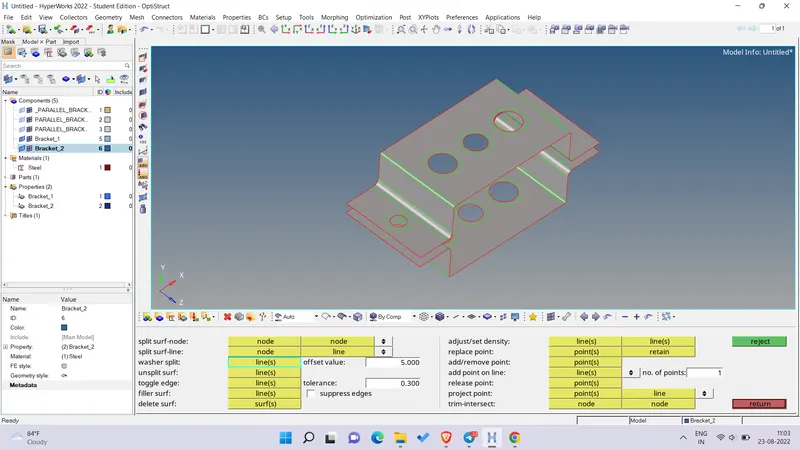
- Before starting with the mesh, we need to create washer splits around the hole area for proper mesh flow using Quick edits > Washer splits. Following is the snippet -
- For meshing, we go to 2D tab > Automesh > Input mesh size as 5mm and mesh type as Mixed and then select the displayed surface and mesh the compoenents -
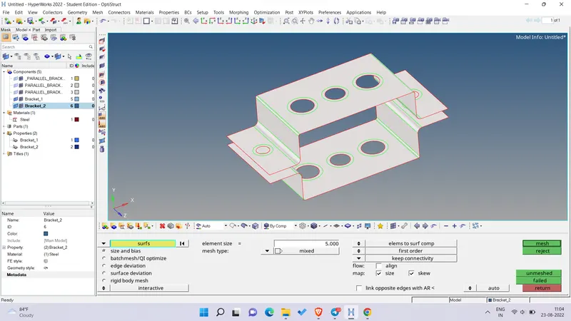
- After meshing, following is the snippet of the graphics area -
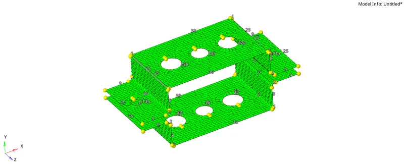
- As the meshing is done, now we need to create 1D elements where we establish links and connection using RBE2 (Rigid) and RBE3 links as per the requirement.
- We start with A hole where we establish RBE2 link where we only constrain translational DOF as shown below -
- For B hole, we create RBE3 links where all DOF are constrained as shown below -
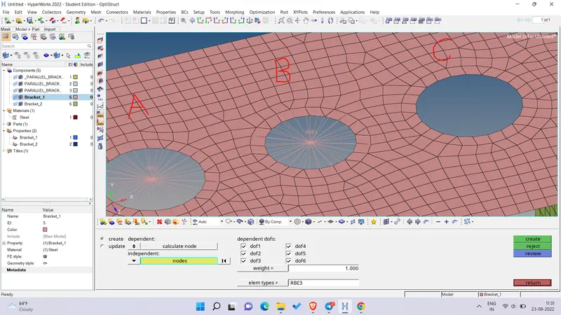
- For C hole, we create RBE3 link by constraining DOFs in only X and Y direction as shown below -
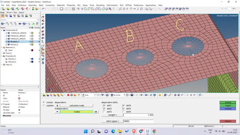
- For D and E hole, we create RBE2 link and constrain all DOF and the whole model after creating the Rigid and RBE3 links for both the brackets is as shown below -
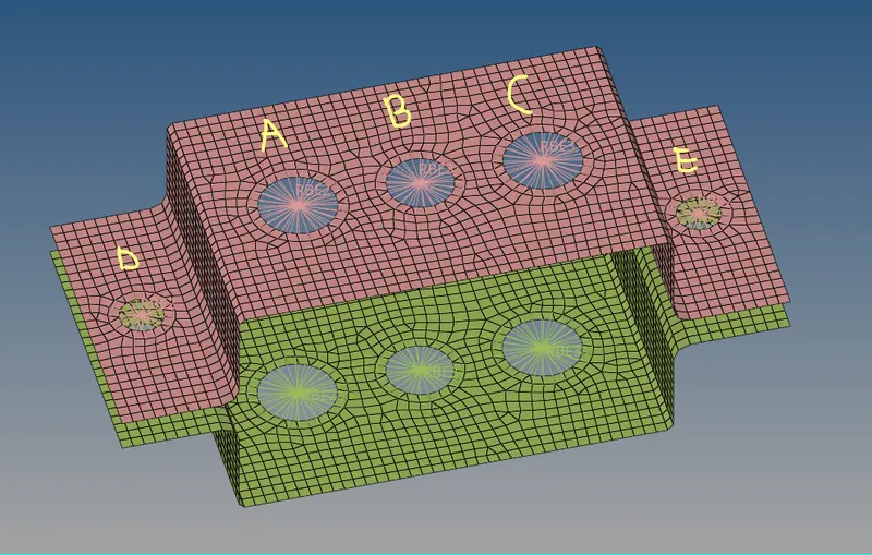
- We need to create 1D elements like Rod, Beam and Bar for proper visualization of the connections between the holes A, B and C etc. So we create these with the help of Hyperbeam as per the dimension given above.
- For Rod element in Hyperbeam, Create > Standard Section > Hypermesh > Thinwalled box and then input the dimension as shown below -
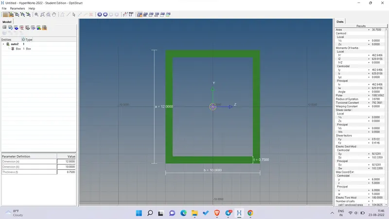
- For Beam element in Hyperbeam, Create > Standard Section > Hypermesh > Standard I Section and then input the dimension as shown below -
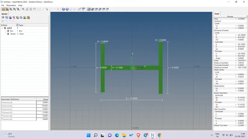
- For Cross Bar element in Hyperbeam, Create > Standard Section >Optistruct > Cross and then input the dimension as shown below -
- Now we need to establish connection between the holes of the brackets.
- For A hole on both the brackets, we establish connection using Rod elements in 1D tab. We select the centre nodes of both A hole on the brackets and select element type as CROD and Property as Rod and create the connection as shown below -
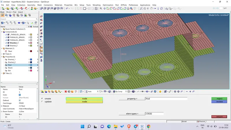
- We have created the Property for the Rod, Beam and Bar as seen in the above figure and some of the values selected are as shown in the table below -
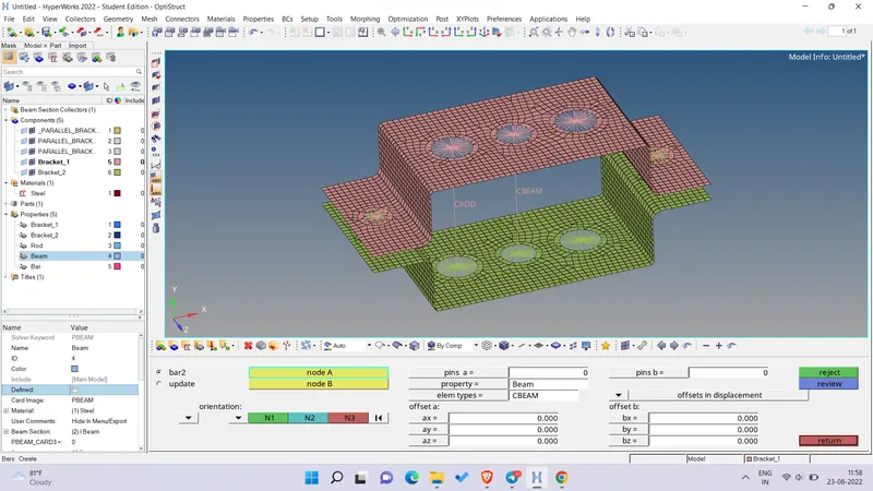
Type Card Image Material Beam Section Rod PROD STEEL Box Beam PBEAM STEEL I Beam Bar PBAR STEEL - For B hole on both the brackets, we establish connection using Bars elements in 1D tab. We select the centre nodes of both B hole on the brackets and select element type as CBEAM and Property as Beam and also select the orientation and create the connection as shown below -
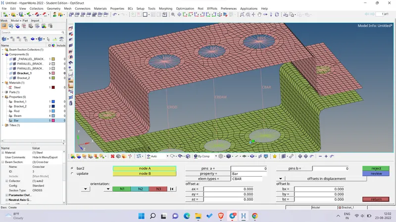
- For C hole on both the brackets, we establish connection using Bars elements in 1D tab. We select the centre nodes of both C hole on the brackets and select element type as CBAR and Property as Bar and also select the orientation and create the connection as shown below -
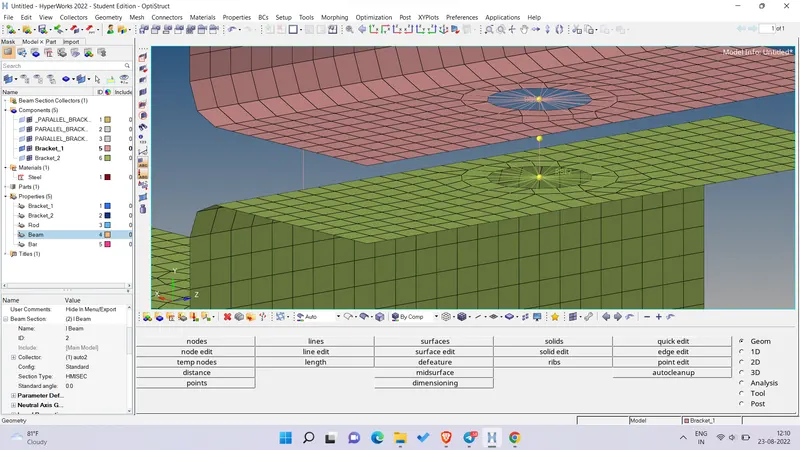
- For D and E hole, we need to create RBE2 connection between the holes of both the brackets and place a mass of 10 in the centre of the RBE2 connection. Therefore, we create a temporary node in between the holes of both brackets wherer we will apply the load as shown below -
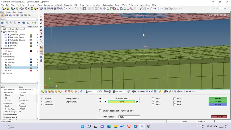
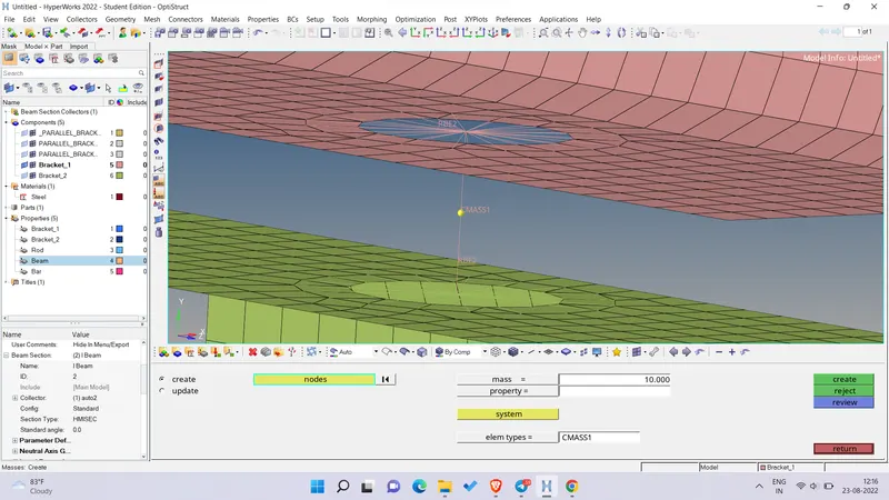
- Now create the RBE2 connection between the temp node and the RBE2 links (hole) on the brackets and place the mass of 10 at the temp node with element type as CMASS1 as shown below -
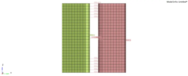
- Lastly, the edges of the 2 brackets needs to connected using spring elements where we just need to select the nodes which are to be connected. The connection is as shown below -
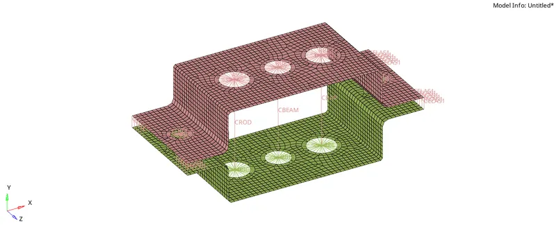
- After completing all the requirements for the model, following is the snippet of the complete model -
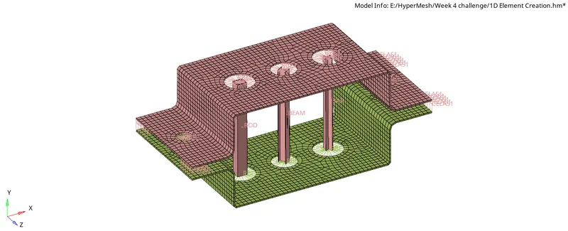
- After switching on the 1D and 2D element detailed representation, following is the snippet of the model -
LEARNINGS -
- Got to apply the new concept of Mid surface extraction and 2D meshing.
- Creation of 1D elements and connection using Hyperbeam.