Creating connection for Rear door
AIM -
- For the given Rear door FE model, Create and Apply different PIDs for different components.
- Perform suitable connections.
PROCEDURE -
1. Importing CAD Model -
- First step is to import/open the CAD model in ANSA and after opening the CAD model following is the GUI of ANSA -
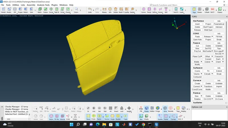
Figure 1 - Meshed model is visible
- After opening the CAD model, Faces > Orient option was selected to modify the orientation of the faces.
- Then we switched to the PID mode.
- Now we need to create different PIDs which will help us in performing connection properly. Below is the snippet for the PIDs created -
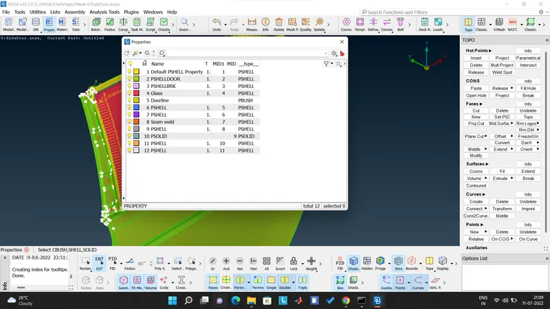
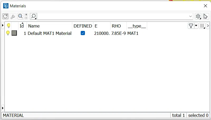
- No geometry errors were present during geometry checks. Then we define the material as shown below -
2.Connections
CASE 1 - WASHER ZONE AND BOLT CONNETCTION
- There are many places where only single connection face is available. So in that case, if the number of nodes are equal to or greater than 6 then we perform Zone cut and make washer area as shown below -
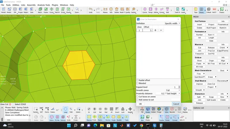
- Washer area is basically created to have good distribution of load.
- If the connection is established without the washer area which is usually done for the elements with number of nodes less than 5, the load will be concentrated on the edges of the element which is accepted but not a good practice.
- After the zone cut, the connection needs to be established. So we move to the NASTRAN deck where we select ELEMENTS > RBE2 (Rigid Body Element 2).
- RBE2 basically defines a rigid body element of form 2 (RBE2) between selected grid points, 3D-points etc.
- We can select the nodes either by Nodes mode or Entity mode. Here we have used Polyarea command from the Entity mode to select the nodes area and zone cut area as shown below -
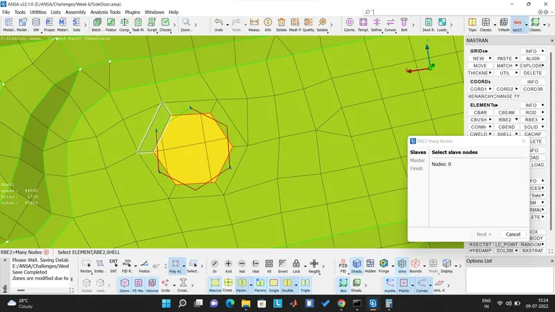
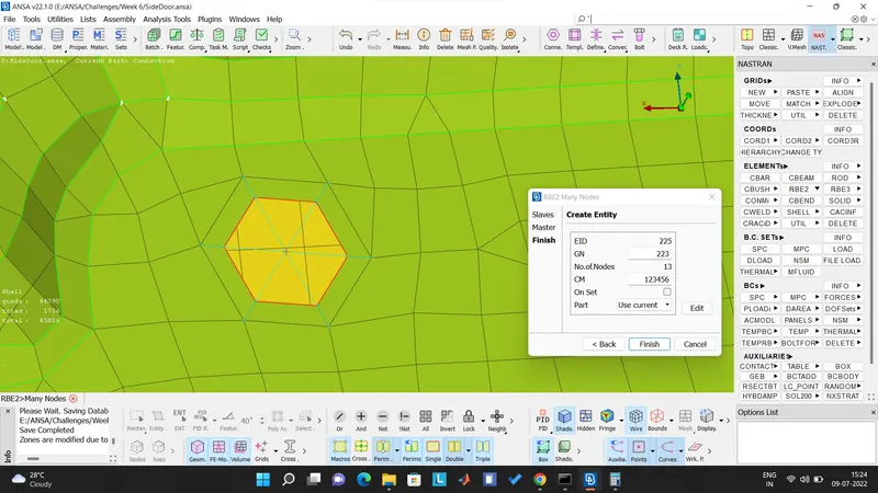
- The RBE2 connection can be visualized by the cyan blue color. The sam
CASE 2 - Multiple PIDs Bolt connection
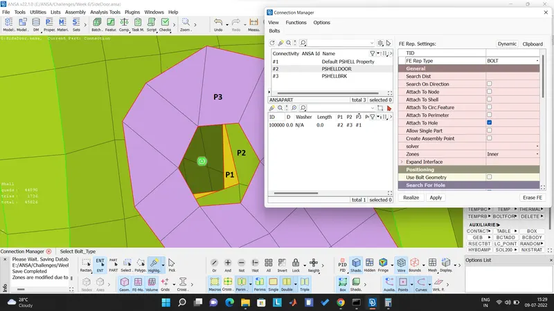
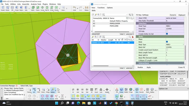
- We first mark the centre of the hole on one of the sharing PIDs with the help of the on COG command. Then convert the point to 3D point and select connection type as Bolt.
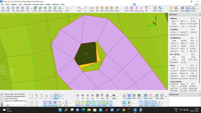
- Now opening Connection Manager and then selecting the 3D bolt point for further connection.
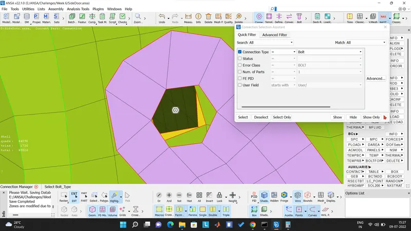
- Now we select the multiple PIDs where the connection is to be realized. In this case we select P1, P2 and P3 and then selecting the FE Rep type as BOLT and specifying the distance and thus realizing the connection as shown below -
CASE 3 - SEAM WELD CONNECTION
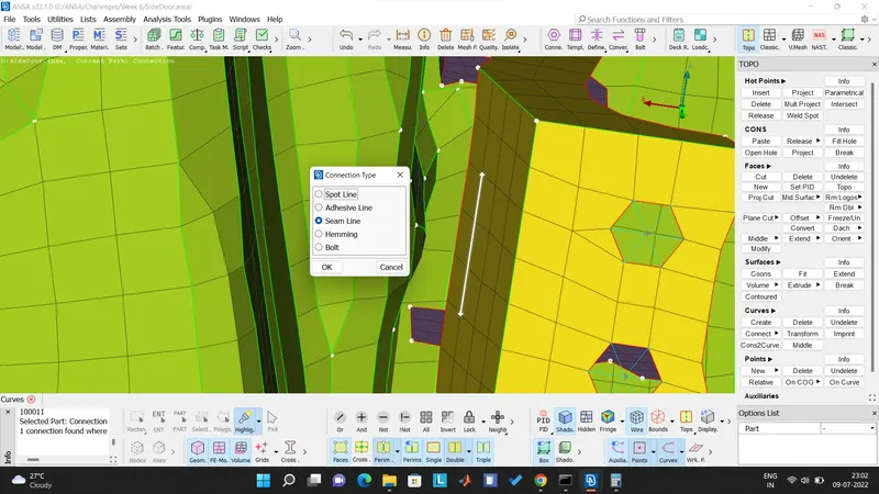
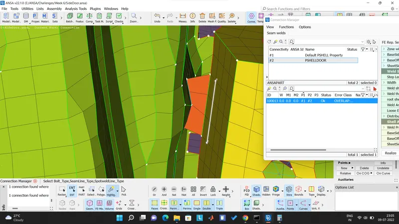
- The hinge part component needs to be seam welded. Here we have realized the same by drawing a curve and then converting the curve to Seam weld connetion type.
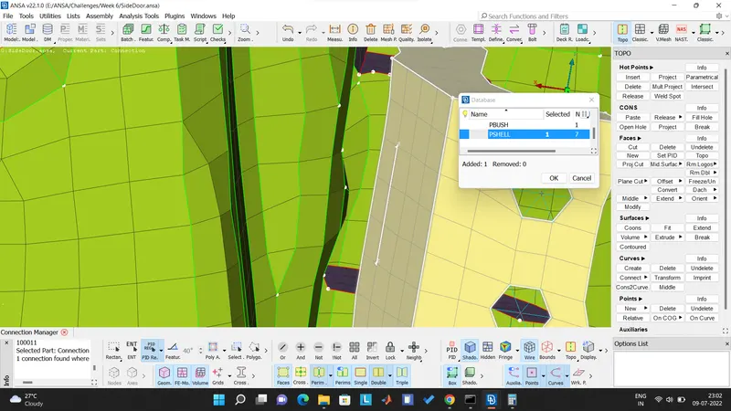
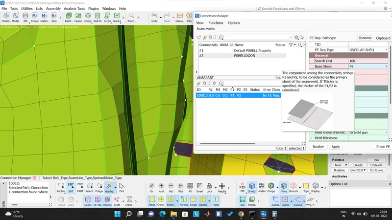
- Now opening the connection manager and then selecting the PIDs to be connected which are P1 and P2.
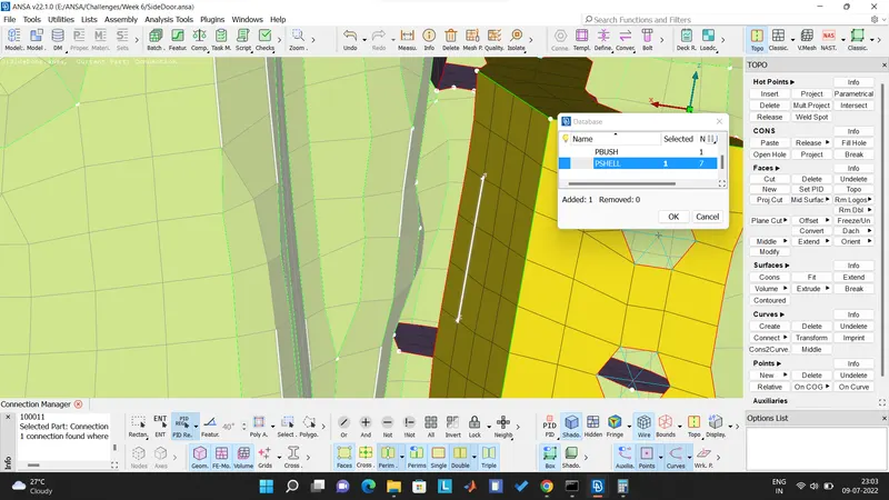
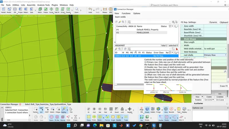
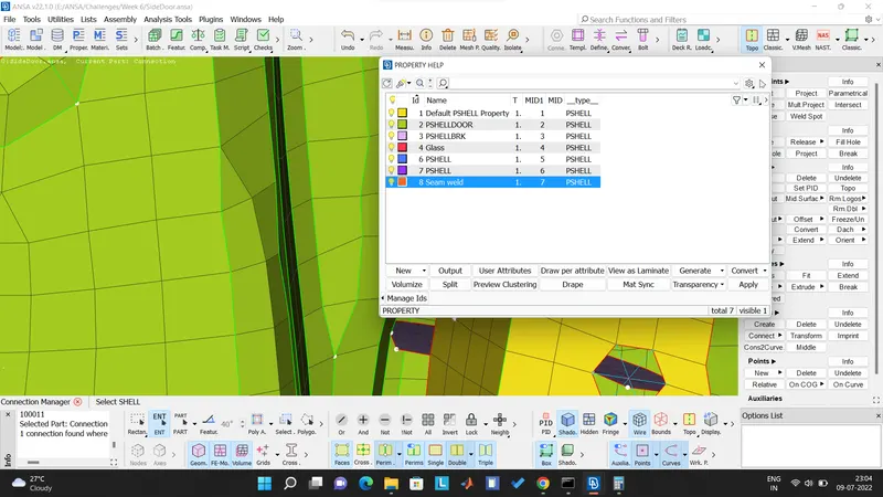
- Now giving the input for search distance as 100 and Base sheet as P2, creating a seam weld PID and selecting Root shells as Primary row for proper realization and visualization of the weld as shown below -
CASE 4 - SPOT WELD CONNECTION
- For spot weld we create a COG point on the element part where weld joint is to be created. Then we convert the point to 3D spot weld point.
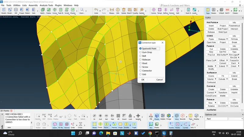
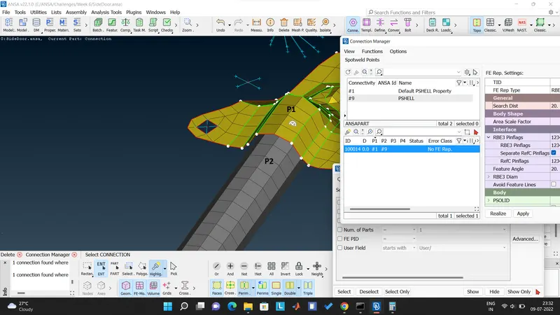
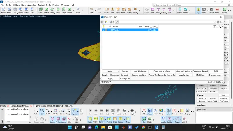
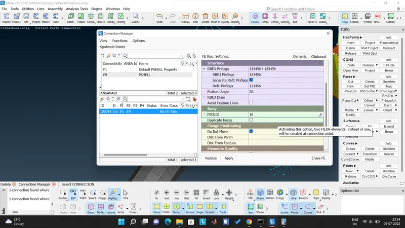
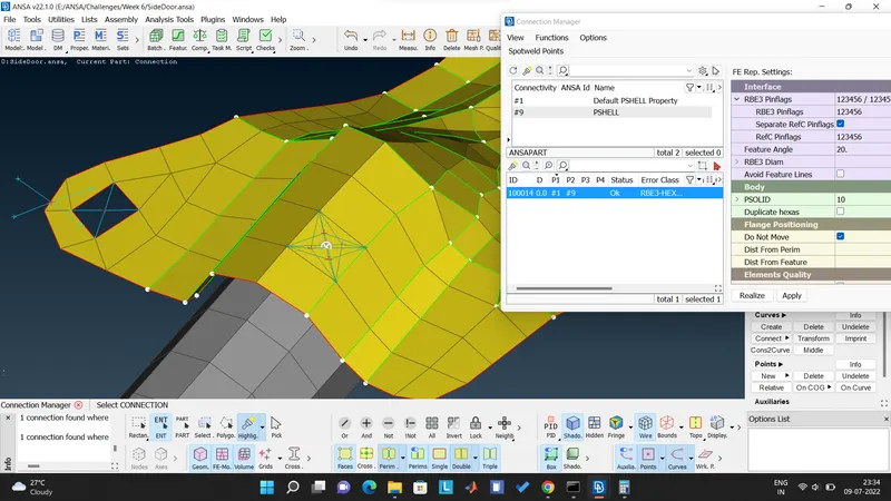
- Then we open the connection manager and select the 3D spot weld point and then define the part to be joined which are P1 and P2, select the FE Rep type as 'RBE3-HEXA-RBE3', define the body element PSOLID for the spot weld and then apply and realize the weld. Below are snippets sequentially -
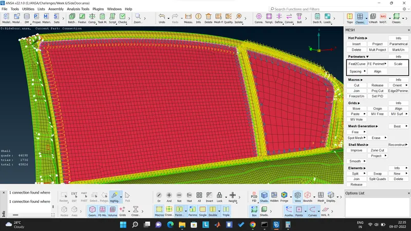
CASE 5 - CBUSH CONNECTION FOR GLASS WINDOW
- For glass window, we first create curve around the glass perimeter and then convert the curve to Spot weld connection type.
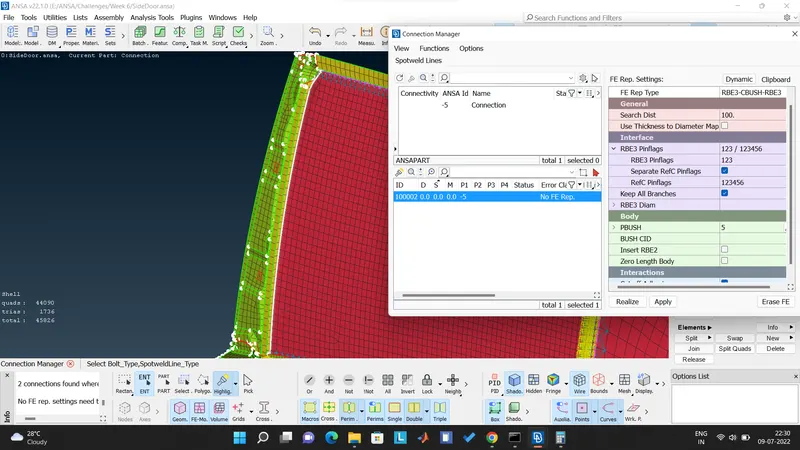
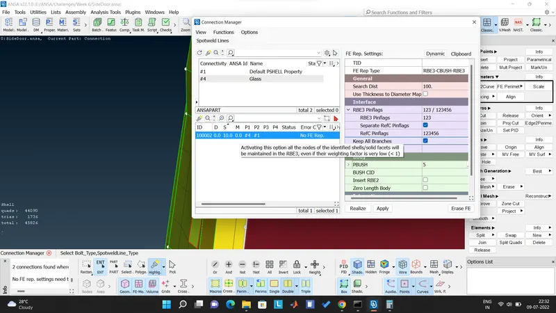
- Then we open the connection manager and select the parts to be connected by selecting the PIDs.
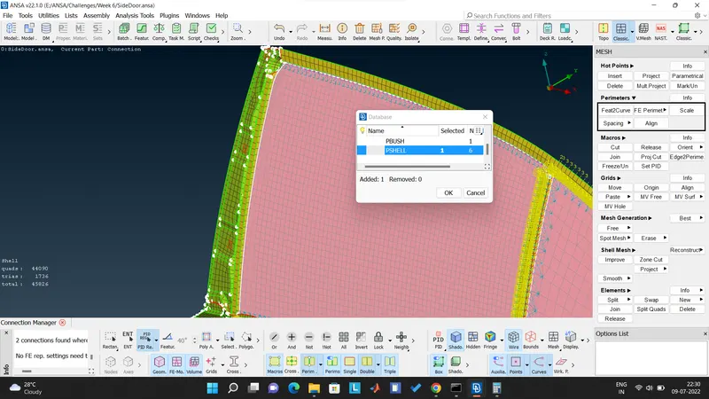
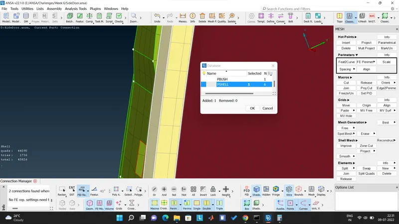
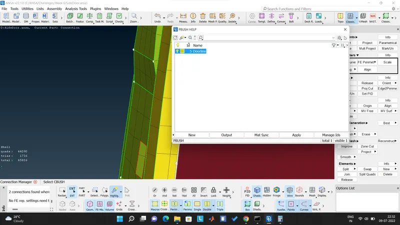
- Defining the PBUSH and saving it as 'Doorline', ticking the "Keep all Branches" and giving input for search distance on the higher side since the distance is more. Below are the snippets -
LEARNINGS -
These are some of my learnings after completing this challenge -
- Can successfully create different connections between the elements by using different methods.
- Got to know about the connection types and significance behind using the specific connection type for a specific joint method.
CONCLUSION -
- We have successfully connected the elements of the side door by creating different PIDs and thus achieving our aim.