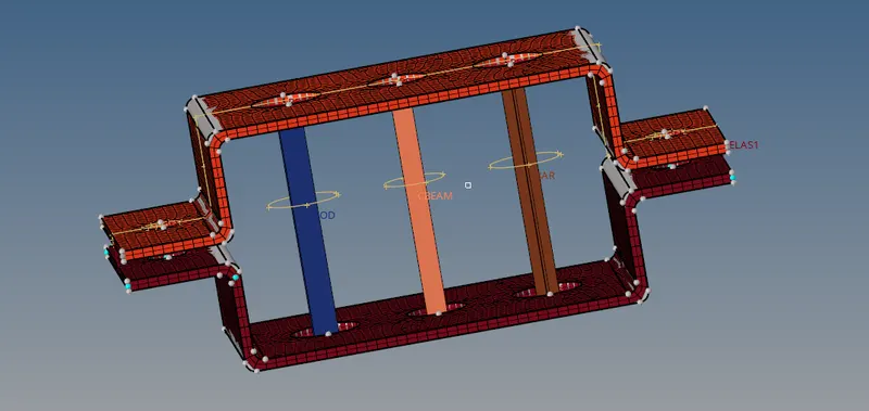
Week 4-1D Element Creation Challenge
Mesh the Given component with the Size of 5 Units. Create 1D elements on the following component with given cross-section and DOF
a. Rod element:- Translational DOF should be Constrained with RBE2 link
Cross-Section: BOX- Dimension a= 12 mm
dimension b=10 mm
Thickness t= 0.75 mm
b. Beam element:- All DOF should be constrained with RBE3 link
Cross-Section: I Section- Dimension a= 8 mm
Dimension b= 10 mm
Dimension c= 8.5 mm
Thickness t1= 0.75 mm
Thickness t2= .6 mm
Thickness t3= .6 mm
c. Bar element:- Constrain only x and y DOFs With RBE3 link
Cross-section: X section- Dimension DIM1= 5 mm
Thickness DIM2= 1.2 mm
Dimension DIM3= 10 mm
Thickness DIM4= 1.2mm
d. & e. Apply the mass of magnitude 10 with the RBE2 link
f. Join the two components with Spring elements
Ans:
- Firstly import the IGES model into the window panel and then find out the thickness of both the brackets.
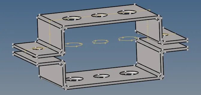
Bracket 1 =5mm
Bracket 2=5mm

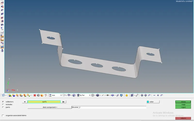
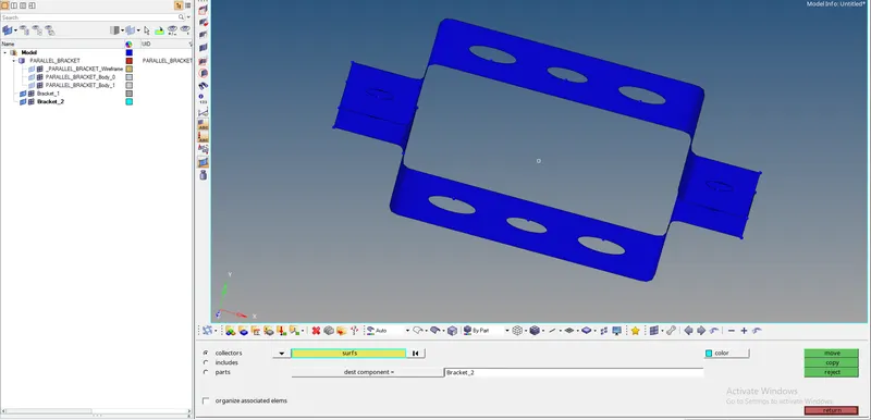
- Now extract the mid surface of the 1st bracket and rename it as bracket_1 and create the new component and name it as bracket_2
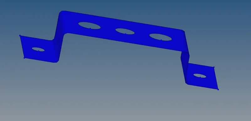

- The creation of a new component is because the extracting of the second bracket is going to merge on the 1st mid surface itself.
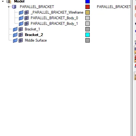
- After the creation of 2nd component now extract the mid surface of the 2nd bracket and move that mid surface into the bracket_2
Tool>organise>see which component is listed>surface>move.

- Now insert the material in the model panel and rename it as steel
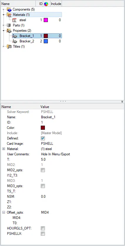
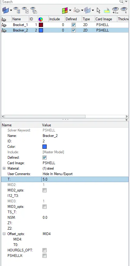
- And also create the two properties name it as Bracket-1 and bracket_2 and assign the material as steel, thickness as 5mm
- Now assign the mid surface brackets properties
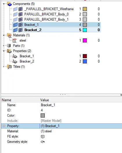
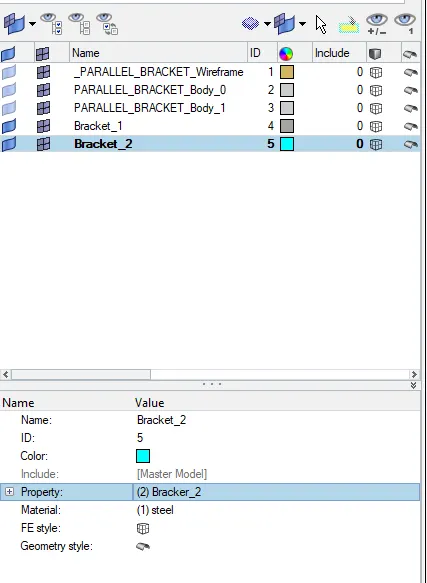
- After creating all this, add a washer split with an offset of 5mm for every hole in the model
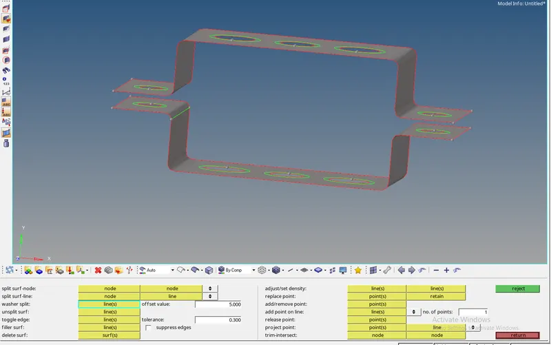
- Now auto mesh the displayed component
- construct the Rbe2 and rbe3 elements as per mentioned in the question and list the dof according to the requirement.
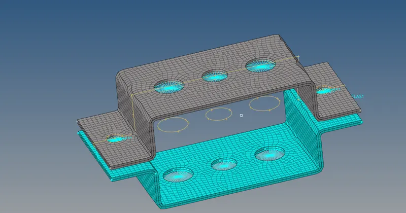
- now create a 1d bar, rod, and beam to the corresponding element as they mentioned in the question.
- In the question they mention that for a, b, and c hole there is a different cross-section
- To create the cross-section for the holes there is a command called hyberbeam where we can select the type of cross and can give the dimension as per the user require
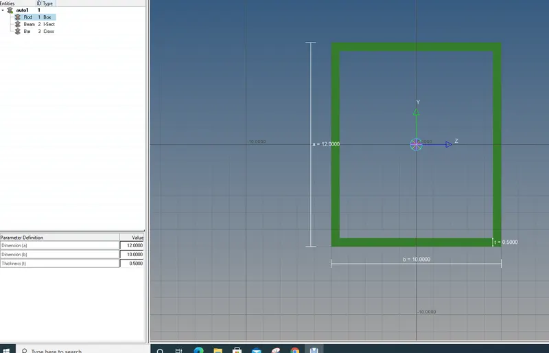
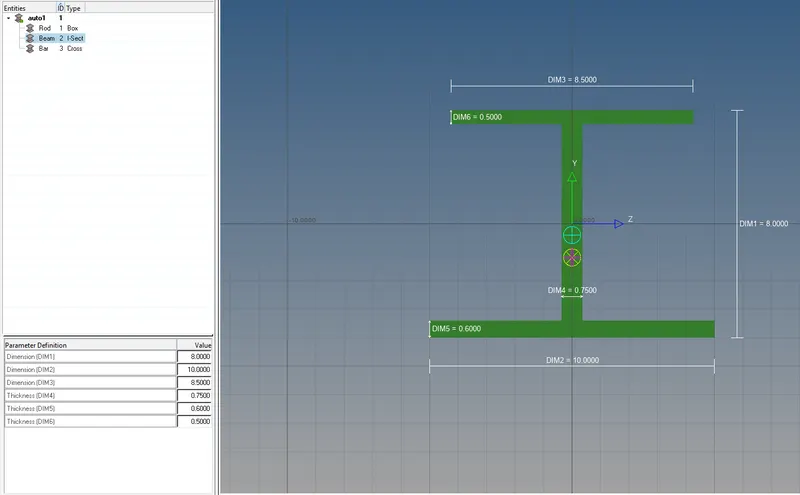
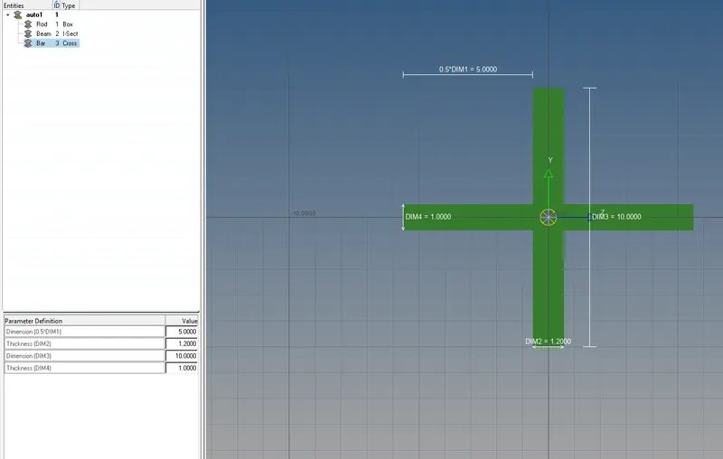
- After creating the cross-sections, import the other 3 properties name them as rod, bar and beam, and assign the card image and beam section as respectively
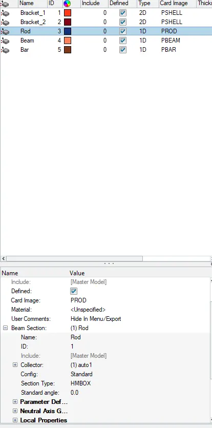
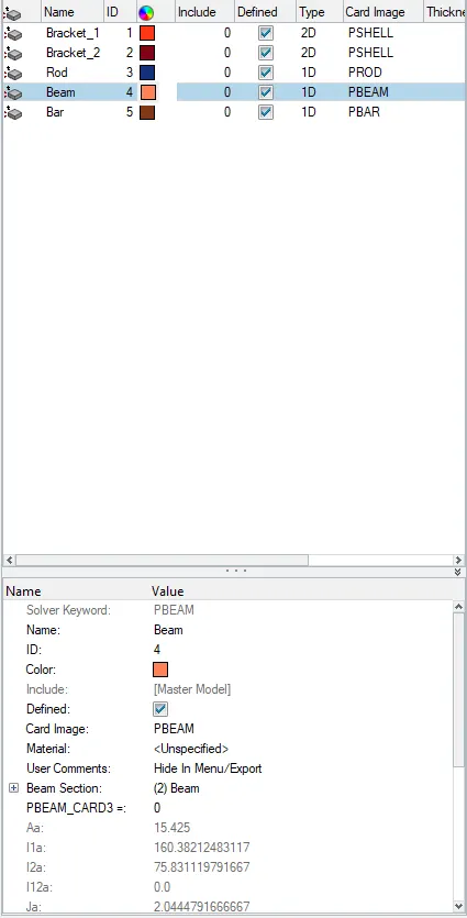
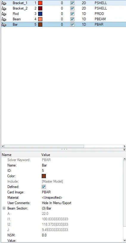
- Once all this done go to the 1d panel and assign the property for rod, bar and beam and update it



- To give the mass and spring just select the node on the element and create it
- Now on the o 2D Transatinal and element representation view