Week 6 Fuel cell powered vehicle model
Make a MATLAB model of fuel cell powered electric vehicle and comment on results
A fuel cell is a device that generates electricity by a chemical reaction. Every fuel cell has two electrodes called, respectively, the anode and cathode. The reactions that produce electricity take place at the electrodes.
Every fuel cell also has an electrolyte, which carries electrically charged particles from one electrode to the other, and a catalyst, which speeds the reactions at the electrodes.
Hydrogen is the basic fuel, but fuel cells also require oxygen. One great appeal of fuel cells is that they generate electricity with very little pollution–much of the hydrogen and oxygen used in generating electricity ultimately combine to form a harmless byproduct, namely water.
One detail of terminology: a single fuel cell generates a tiny amount of direct current (DC) electricity. In practice, many fuel cells are usually assembled into a stack. Cell or stack, the principles are the same.
Need of fuel cells:
Fuel cells can be used in a wide range of applications, including transportation, material handling, stationary, portable, and emergency backup power applications.
Fuel cells have several benefits over conventional combustion-based technologies currently used in many power plants and passenger vehicles. Fuel cells can operate at higher efficiencies than combustion engines, and can convert the chemical energy in the fuel to electrical energy with efficiencies of up to 60%.
Fuel cells have lower emissions than combustion engines. Hydrogen fuel cells emit only water, so there are no carbon dioxide emissions and no air pollutants that create smog and cause health problems at the point of operation. Also, fuel cells are quiet during operation as they have fewer moving parts.
There are four basic elements of a PEM Fuel Cell:
The anode, the negative post of the fuel cell, has several jobs. It conducts the electrons that are freed from the hydrogen molecules so that they can be used in an external circuit. It has channels etched into it that disperse the hydrogen gas equally over the surface of the catalyst.
The cathode, the positive post of the fuel cell, has channels etched into it that distribute the oxygen to the surface of the catalyst. It also conducts the electrons back from the external circuit to the catalyst, where they can recombine with the hydrogen ions and oxygen to form water.
The electrolyte is the proton exchange membrane. This specially treated material, which looks something like ordinary kitchen plastic wrap, only conducts positively charged ions. The membrane blocks electrons. For a PEMFC, the membrane must be hydrated in order to function and remain stable.
The catalyst is a special material that facilitates the reaction of oxygen and hydrogen. It is usually made of platinum nanoparticles very thinly coated onto carbon paper or cloth. The catalyst is rough and porous so that the maximum surface area of the platinum can be exposed to the hydrogen or oxygen. The platinum-coated side of the catalyst faces the PEM.
The main components of a fuel cell:
An automotive fuel cell system can use a variety of fuels, and the selection of a fuel depends on factors such as the fuel supply infrastructure, the cost of fuel, the complexity and cost of storage, safety, environmental implications, and the national energy policy. The proper storage of hydrogen is critical for the mass commercialization of fuel cell vehicles. Hydrogen can be stored in many forms, such as compressed gas, liquid, or as metal hyrides. Tanks that hold compressed gases are large and bulky. The average fuel efficiency of new cars is between 20 and 30 mpg; European and Japanese cars average even less. Current vehicles hold 10 to 16 gallons of gasoline, or 30 to 45 liters of space. Since hydrogen has twice the efficiency of gasoline vehicles, they can theoretically store between 5 to 8 kg of hydrogen, which is equivalent to between 200 and 400 L—a sizable reduction in the space needed for fuel. Liquid hydrogen tanks are less bulky but must be stored at extremely low temperatures.
Working Principle of fuel cells:
The purpose of a fuel cell is to produce an electrical current that can be directed outside the cell to do work, such as powering an electric motor or illuminating a light bulb or a city. Because of the way electricity behaves, this current returns to the fuel cell, completing an electrical circuit. (To learn more about electricity and electric power, visit "Throw The Switch" on the Smithsonian website powering a Generation of change). The chemical reactions that produce this current are the key to how a fuel cell works.
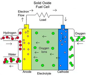
There are several kinds of fuel cells, and each operates a bit differently. But in general terms, hydrogen atoms enter a fuel cell at the anode where a chemical reaction strips them of their electrons. The hydrogen atoms are now "ionized," and carry a positive electrical charge. The negatively charged electrons provide the current through wires to do work. If alternating current (AC) is needed, the DC output of the fuel cell must be routed through a conversion device called an inverter.
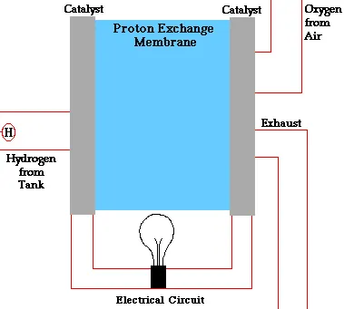 Graphic by Marc Marshall, Schatz Energy Research Center |
Oxygen enters the fuel cell at the cathode and, in some cell types (like the one illustrated above), it there combines with electrons returning from the electrical circuit and hydrogen ions that have traveled through the electrolyte from the anode. In other cell types the oxygen picks up electrons and then travels through the electrolyte to the anode, where it combines with hydrogen ions.
The electrolyte plays a key role. It must permit only the appropriate ions to pass between the anode and cathode. If free electrons or other substances could travel through the electrolyte, they would disrupt the chemical reaction.
Whether they combine at anode or cathode, together hydrogen and oxygen form water, which drains from the cell. As long as a fuel cell is supplied with hydrogen and oxygen, it will generate electricity.
Even better, since fuel cells create electricity chemically, rather than by combustion, they are not subject to the thermodynamic laws that limit a conventional power plant .Therefore, fuel cells are more efficient in extracting energy from a fuel. Waste heat from some cells can also be harnessed, boosting system efficiency still further.
Different types of fuel cells.
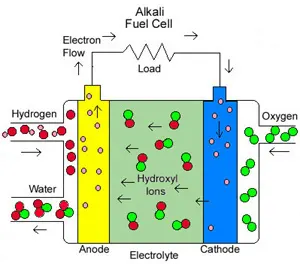
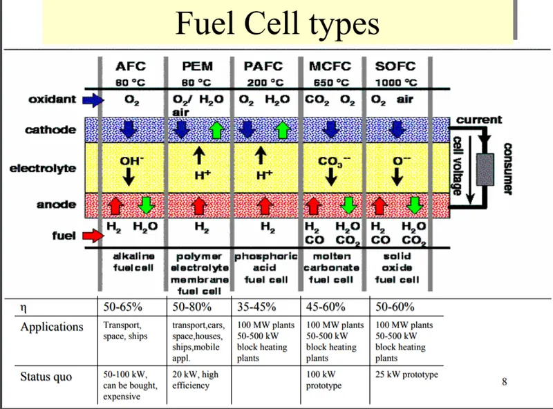
Alkali fuel cells operate on compressed hydrogen and oxygen. They generally use a solution of potassium hydroxide (chemically, KOH) in water as their electrolyte. Efficiency is about 70 percent, and operating temperature is 150 to 200 degrees C, (about 300 to 400 degrees F). Cell output ranges from 300 watts (W) to 5 kilowatts (kW). Alkali cells were used in Apollo spacecraft to provide both electricity and drinking water. They require pure hydrogen fuel, however, and their platinum electrode catalysts are expensive. And like any container filled with liquid, they can leak.
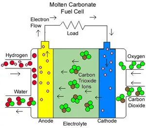
Molten Carbonate fuel cells (MCFC) use high-temperature compounds of salt (like sodium or magnesium) carbonates (chemically, CO3) as the electrolyte. Efficiency ranges from 60 to 80 percent, and operating temperature is about 650 degrees C (1,200 degrees F). Units with output up to 2 megawatts (MW) have been constructed, and designs exist for units up to 100 MW. The high temperature limits damage from carbon monoxide "poisoning" of the cell and waste heat can be recycled to make additional electricity. Their nickel electrode-catalysts are inexpensive compared to the platinum used in other cells. But the high temperature also limits the materials and safe uses of MCFCs–they would probably be too hot for home use. Also, carbonate ions from the electrolyte are used up in the reactions, making it necessary to inject carbon dioxide to compensate.
Phosphoric Acid fuel cells (PAFC) use phosphoric acid as the electrolyte. Efficiency ranges from 40 to 80 percent, and operating temperature is between 150 to 200 degrees C (about 300 to 400 degrees F). Existing phosphoric acid cells have outputs up to 200 kW, and 11 MW units have been tested. PAFCs tolerate a carbon monoxide concentration of about 1.5 percent, which broadens the choice of fuels they can use. If gasoline is used, the sulfur must be removed. Platinum electrode-catalysts are needed, and internal parts must be able to withstand the corrosive acid.
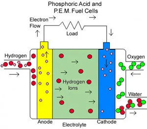 |
Proton Exchange Membrane (PEM) fuel cells work with a polymer electrolyte in the form of a thin, permeable sheet. Efficiency is about 40 to 50 percent, and operating temperature is about 80 degrees C (about 175 degrees F). Cell outputs generally range from 50 to 250 kW. The solid, flexible electrolyte will not leak or crack, and these cells operate at a low enough temperature to make them suitable for homes and cars. But their fuels must be purified, and a platinum catalyst is used on both sides of the membrane, raising costs.
Solid Oxide fuel cells (SOFC) use a hard, ceramic compound of metal (like calcium or zirconium) oxides (chemically, O2) as electrolyte. Efficiency is about 60 percent, and operating temperatures are about 1,000 degrees C (about 1,800 degrees F). Cells output is up to 100 kW. At such high temperatures a reformer is not required to extract hydrogen from the fuel, and waste heat can be recycled to make additional electricity. However, the high temperature limits applications of SOFC units and they tend to be rather large. While solid electrolytes cannot leak, they can crack.
MATLAB model of fuel cell powered electric vehicle
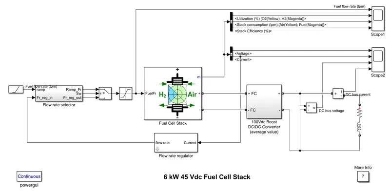
Blocks and parameters used:
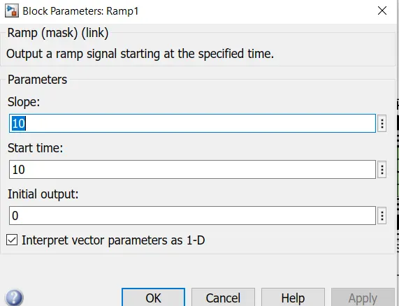
1.Ramp:The Ramp block generates a signal that starts at a specified time and value and changes by a specified rate. The block's Slope, Start time, and Initial output parameters determine the characteristics of the output signal. All must have the same dimensions after scalar expansion.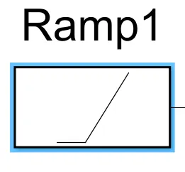
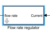
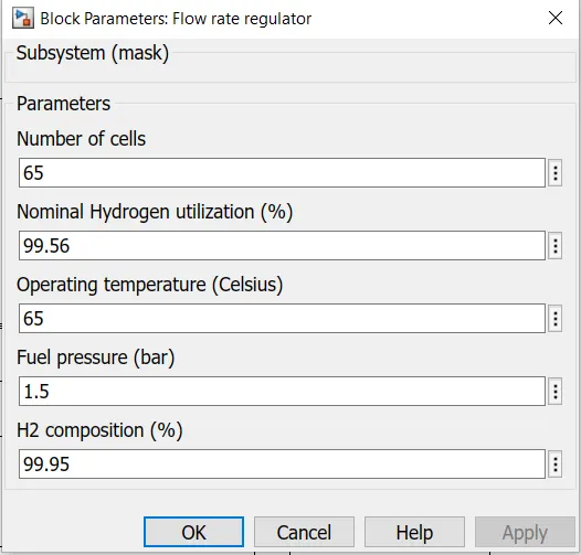
2.Flow rate selector:
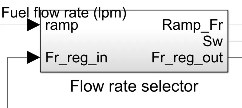
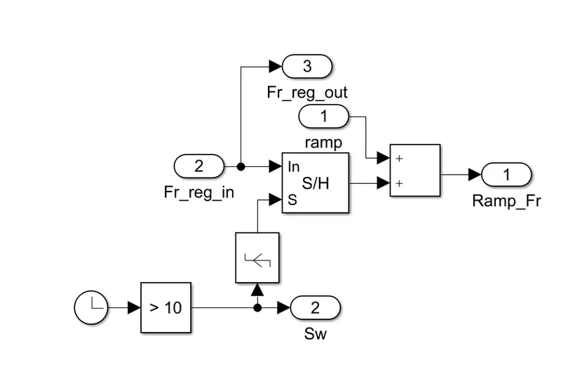
It selects and provide the required output,for any input to understand this block more clearly.
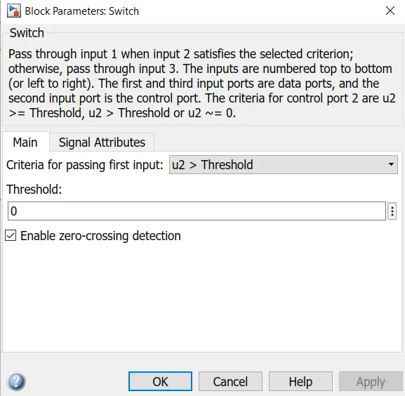
3.Switch: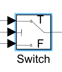
The Switch block models a switch controlled by an external physical signal. If the external physical signal PS is greater than the value specified in the Threshold parameter, then the switch is closed, otherwise the switch is open.
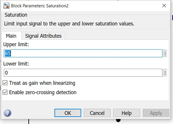
4.Saturation:
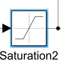
saturation creates a default saturation [NaN NaN]. The initial value of the linear interval is determined from the estimation data range during estimation using nlhw.
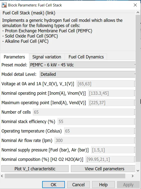
5.Fuel cell stack:
The Fuel Cell Stack block implements a generic model parameterized to represent most popular types of fuel cell stacks fed with hydrogen and air.
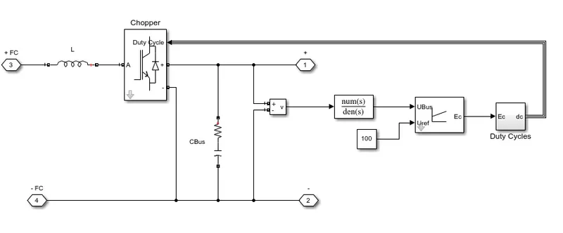
6.DC/DC boost converter:
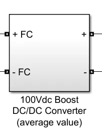
The Average-Value DC-DC Converter block represents a controlled average-value DC-DC converter. You can program the block as a buck converter, boost converte
The powergui block allows you to choose one of these methods to solve your circuit:
-
Continuous, which uses a variable-step solver from Simulink
-
Discretization of the electrical system for a solution at fixed time steps
-
Continuous or discrete phasor solution.
Results:
Scope1:
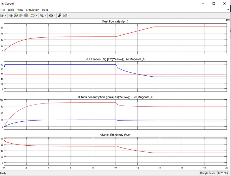
1.Flow rate:From 0 to 10 sec of the time,the flow rate starts increasing and remains constant,until it reaches 50 lpm.After 10sec of the time,the flow rate increases upto 95 lpm which is attrained in 3.5 sec of the time.
2.Utilization:As the flow rate is increased to 95lpm,ther ecan be seen a reduction in the utilzation of hydrogen 100% to 42% where as oxygen remains constant with the value of 60%.
3.Stack consumption(lpm):We can see in the plot that upto 10 sec,the oxygen and hydrogen consumption gradually increases and remains constant uoto 10 sec again after 10 sec the hydrogen and oxygen consumption decreases and reamins constant.
4.Stack efficiency(%):At time t=0 due to transient state the efficiency first increases and then decreases and remains constant,with the constant stack consumption,efficiency again,decreases and remains constant after 10 sec.
Scope2:
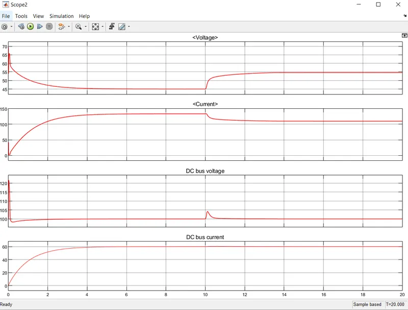
1.Voltage and Current:Both voltage and cuurent changes its value due to transient state.We can see voltage gets down and remians constant,where as current goes up gradually and remains constant upto 10 sec of simulation.After 10 sec with the increase in flow rate voltage of the system increases and to compensate with that currentvalue got decreased.
2.DC bus Voltage and Current:The only change in voltage and current can be seen at transient state of the system.Otherwise there is no change in the DC bus voltage as DC/DC converter of 100 V dc is taken into consideration.