Week 6 - CHT Analysis on a Graphics card
Statement:
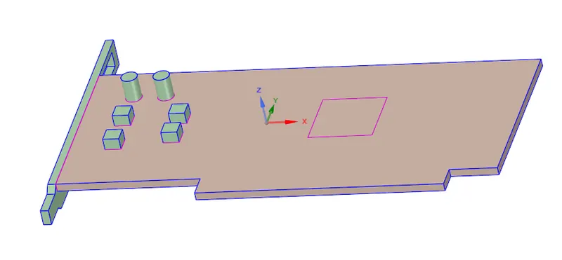
Perform a steady-state conjugate heat transfer analysis on a model of a graphics card. You can use appropriate materials of your choice for the simulation. Make sure to properly define the correct solid and fluid zones. Refer the video for further clarification and the model is provided below the video.
Run the simulation for best possible mesh with combination of coarse and refined mesh in different regions. Explain the reason for choosing the particular mesh settings.
Objectives
- Run the simulation by varying the velocity from 1m/sec to 5m/sec for at least 3 velocities and discuss the results.
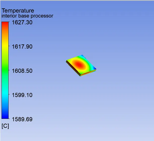
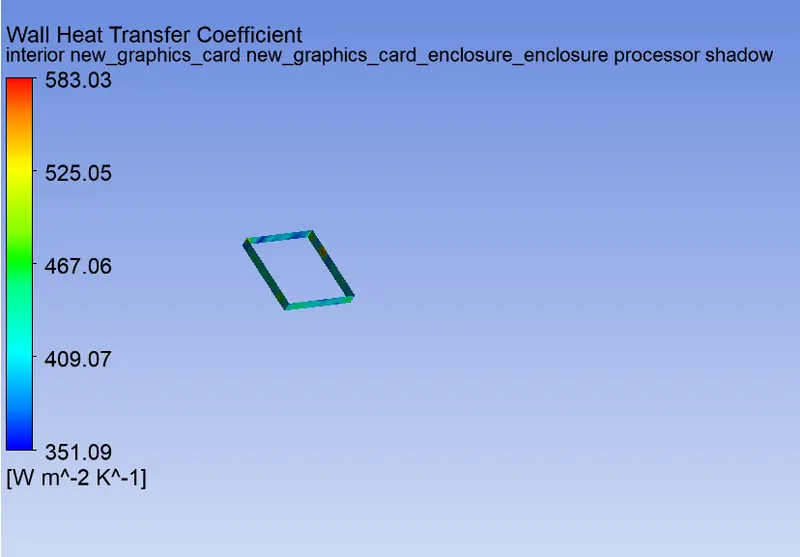
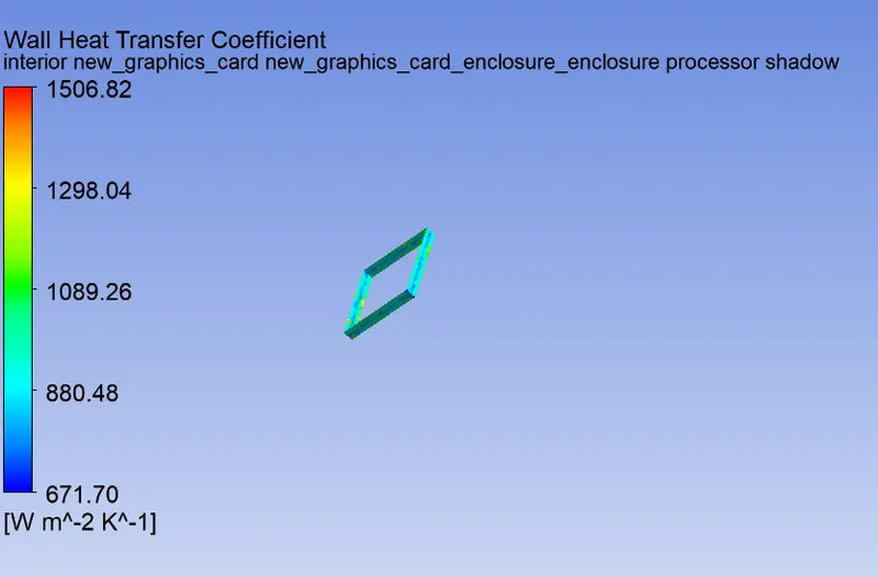
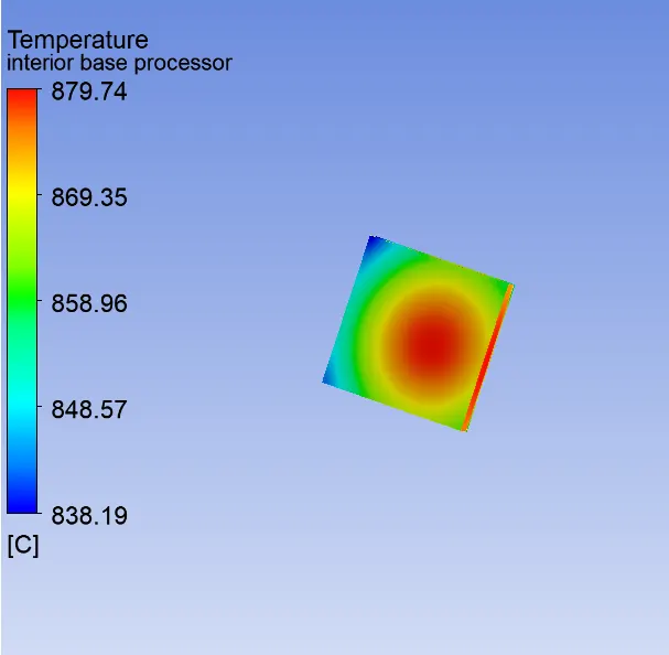
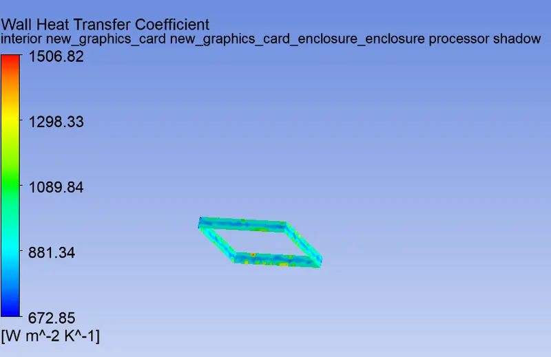
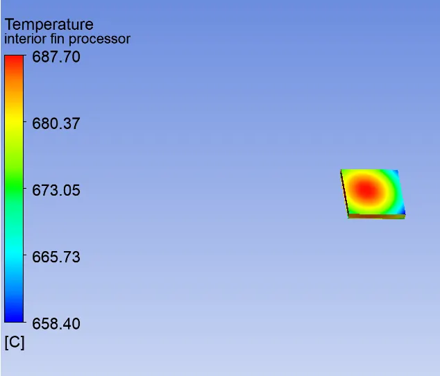
- Find out the maximum temperature and heat transfer coefficient attained by the processor.
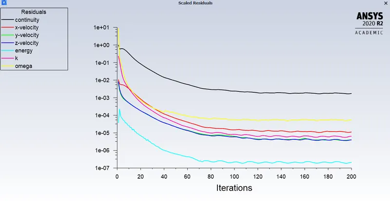
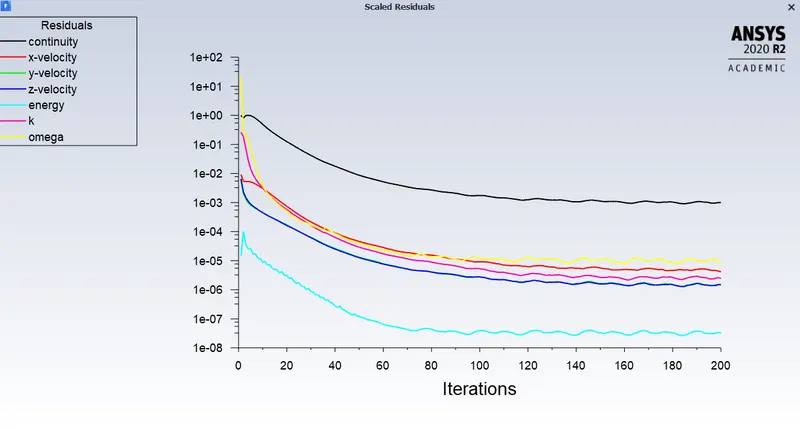
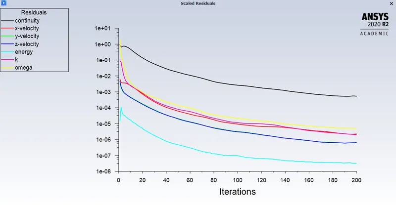
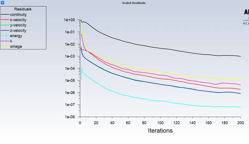
- Prove that the simulation has achieved convergence with appropriate images and plots.
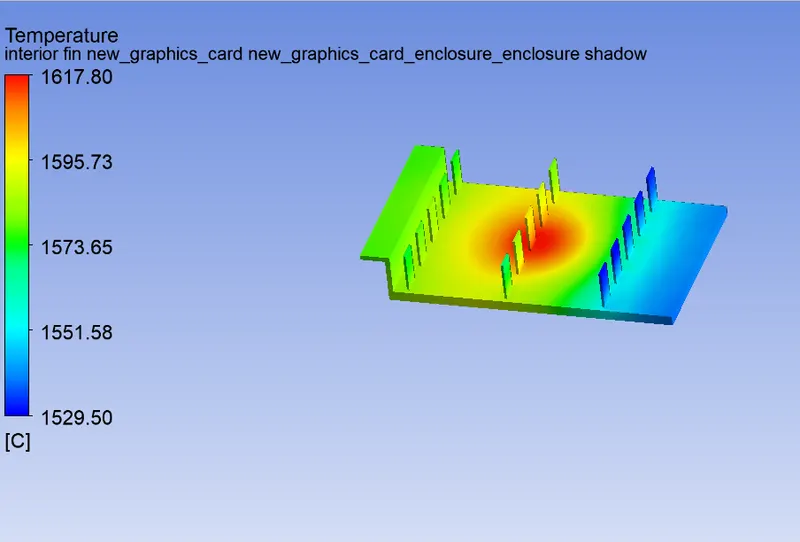
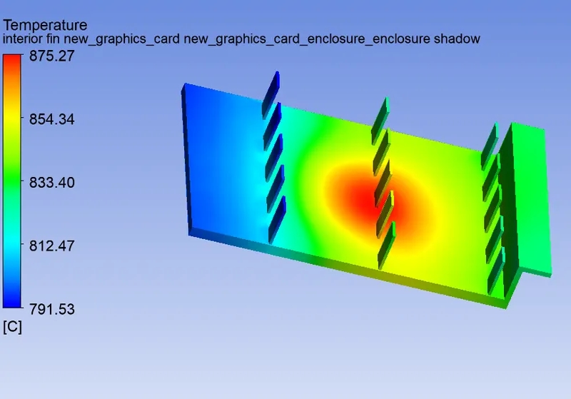
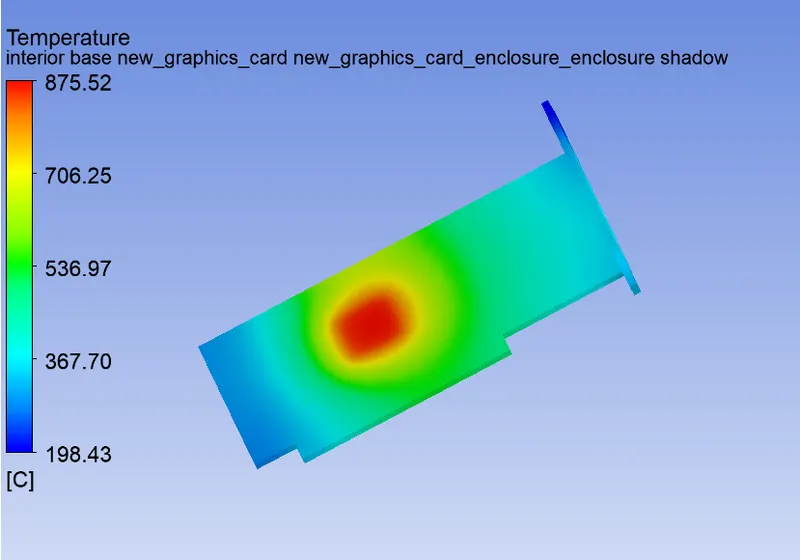
- Identify potential hotspots on the model.
"Heat transfer" is known as the flow of thermal energy from one region to another region occupied by any matter (solids and fluids) where the rate of heat transfer is proportional to the temperature difference between the regions/matter. “Conjugate heat transfer” (CHT) is used to describe the variation of temperature between the solids and fluids due to the exchange of thermal energy between them.
Modes of heat transfer
-
Heat Transfer in a Solid - Conduction: Diffusion of heat due to temperature gradients in solids. A measure of the amount of conduction for a given gradient is heat conductivity. Conduction is described by Fourier’s law defining the conductive heat flux, q, proportional to the temperature gradient
q = -k∇T
For a time-dependent problem, the temperature field in an immobile solid verifies the following form of the heat equation:
-
Heat Transfer in a Fluid - Convection: When heat is carried away by moving fluid. The flow can either be caused by external influences, forced convection or by buoyancy forces, natural convection.
Due to the fluid motion, there are three contributions to the heat transfer:
1. Convective contribution: Depending on the properties of the fluid and its region of flow, the domination of conduction and convection varies.
2. Viscous effects: Due to the fluid flow, the viscosity creates heat. This effect is often neglected due to its negligible value but should be taken into account for high-velocity cases.
3. Density effects: When the density becomes related to the temperature, the domain will have different densities at different locations based on the temperature distribution. This variation in density can cause the compression which in-turn generates the heat.
In addition to conduction due to these contributions, the transient heat equation for the temperature field in a fluid:
-
Heat transfer due to Radiation: Transfer of energy by electromagnetic waves between surfaces with different temperatures, separated by a medium that is at least partially transparent to the (infrared) radiation. Radiation is especially important at high temperatures, e.g. during combustion processes, but can also have a measurable effect at room temperatures.
Geometry setup:
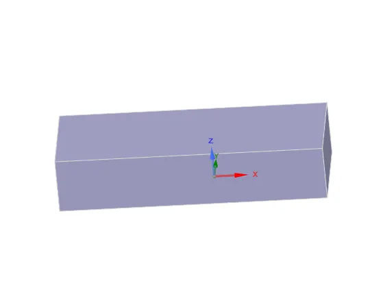
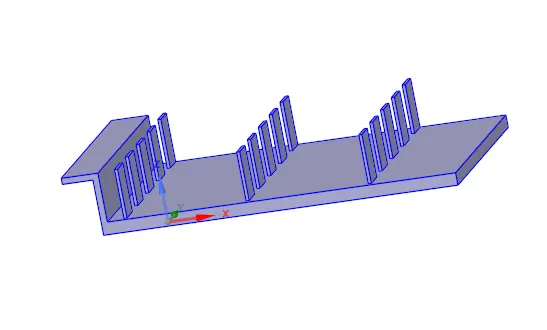
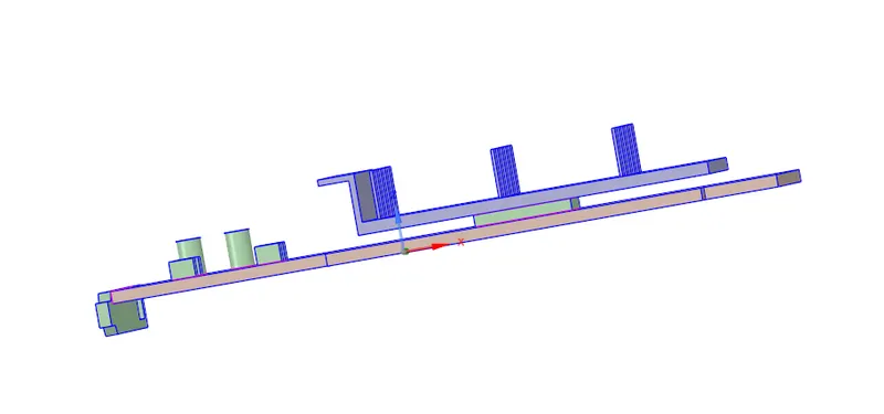
- Import the model into the SpaceClaim
- Click on share prep to view any edges in interference so that conformal mesh can be achieved between different components
- Share topology has to be enabled between the different components so that necessary information can be shared between different zones of the mesh.
Mesh setup:
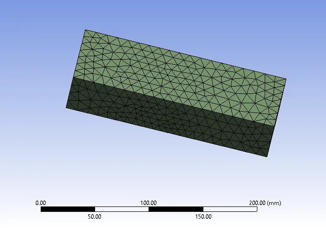
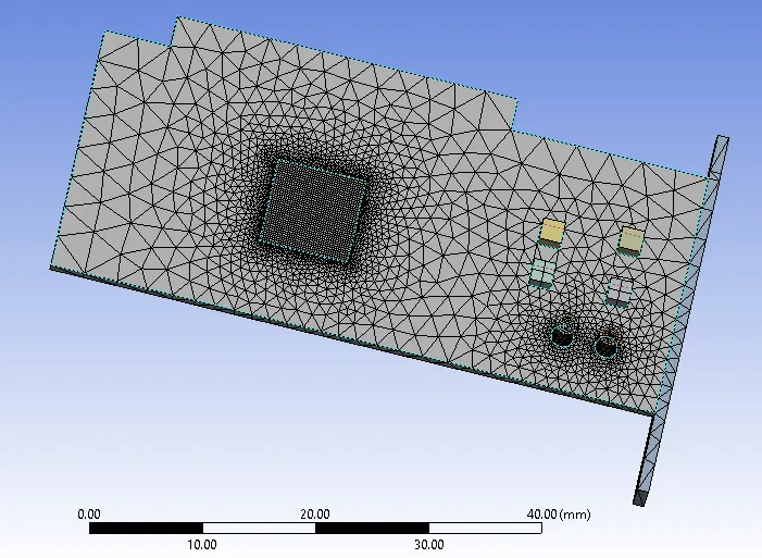
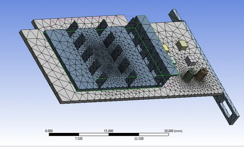
- After creating the geometry of the model open the mesh and give a name to the different components mainly base, fin, and processor
- mesh with a combination of coarse and refined mesh in different regions
- For the base mesh case enclosure, elemental size is 10mm, for fin 5mm, for processor 0.5mm, and for base 5mm.
- For the refined case enclosure, elemental size is 10mm, for fin 5mm, for processor 0.2mm, and for base 3mm.
- Now generate the mesh and update it
Fluent setup:
setting up the physics:
- pressure-based solver and steady time
- enable the energy and take k omega as viscous model
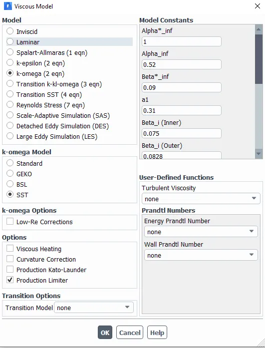
- inlet velocity 1m/s to 5m/s
Materials:
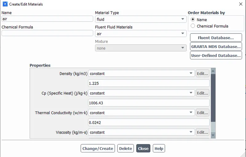
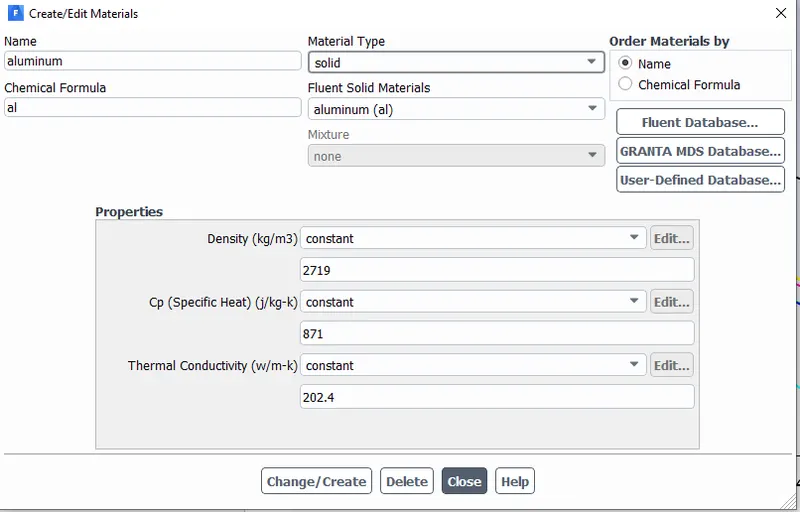
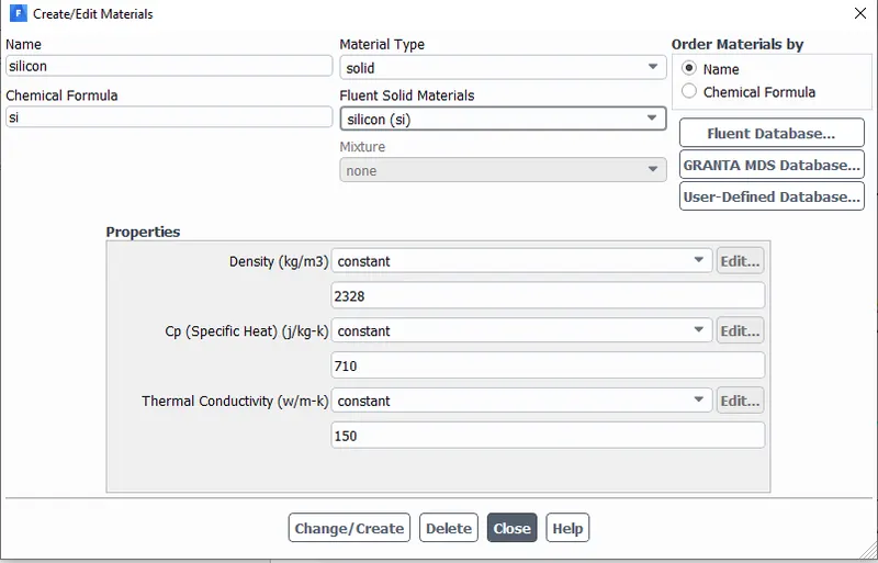
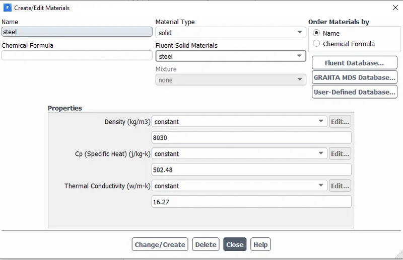
- Here we are using different materials for all component
Aluminum for fin
Steel for base
silica for processor
- After creating the materials assign the material for the components using the cell zones
- Enable the source term for the processor, here we assume 85W power generation processor
Let the processor consume 85 W of power to work.
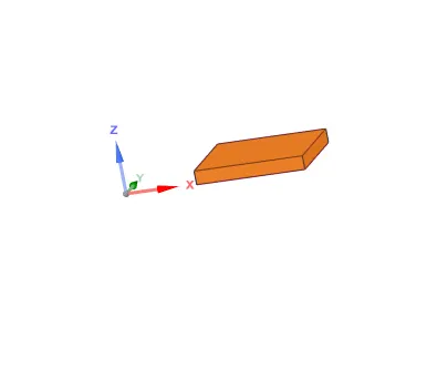
The dimension of the processor = 8*8*1 mm^3
So, the Energy produced by the processor is 1328125000 w/m^3.
Base mesh:
- Inlet velocity 1m/s
- Elemental size for Enclosure 10mm, Fin and base 5mm, and for processor 0.5mm
- Total number of elements = 65258
- Residual plot:
- Temperature and wall HT co-efficient of processor
Potential hotspots on the fin and base:
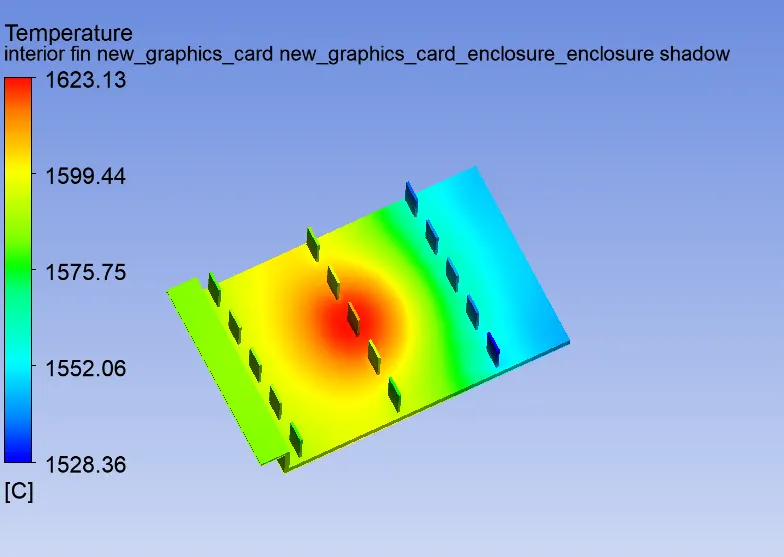
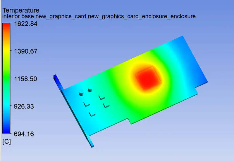
Temperature and wall HT co-efficient of graphic card:
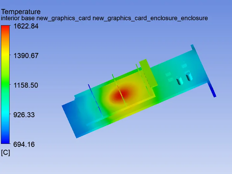
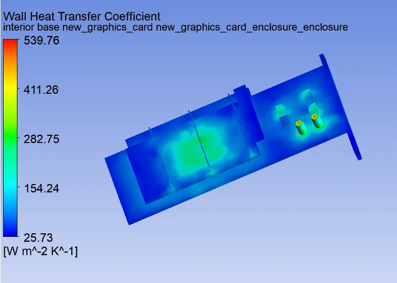
refined
Case 1:
- Inlet velocity 1m/s
- Elemental size for Enclosure 10mm, Fin 5mm , base 3mm, and for processor 0.2mm
- Total number of elements = 267268
Residual plot:
Temperature and wall HT co-efficient of processor

Potential hotspots on the fin and base:
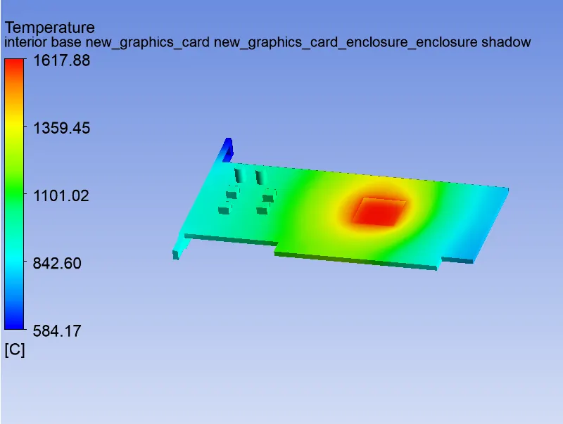
Temperature and wall HT co-efficient of graphic card:
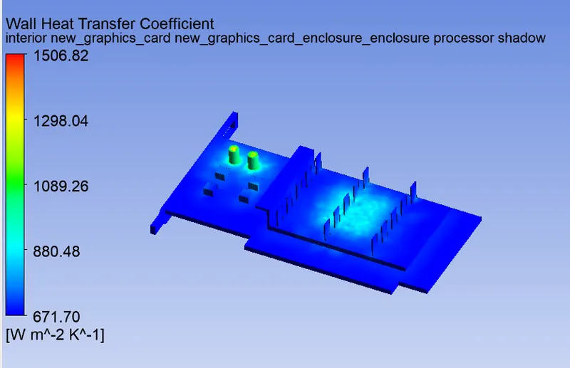
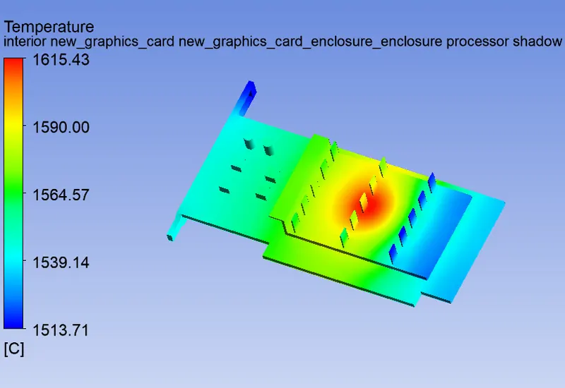
Case 2:
- Inlet velocity 3m/s
- Elemental size for Enclosure 10mm, Fin 5mm , base 3mm, and for processor 0.2mm
- Total number of elements = 267268
Residual plot:
Temperature and wall HT co-efficient of the processor:
Potential hotspots on the fin and base:
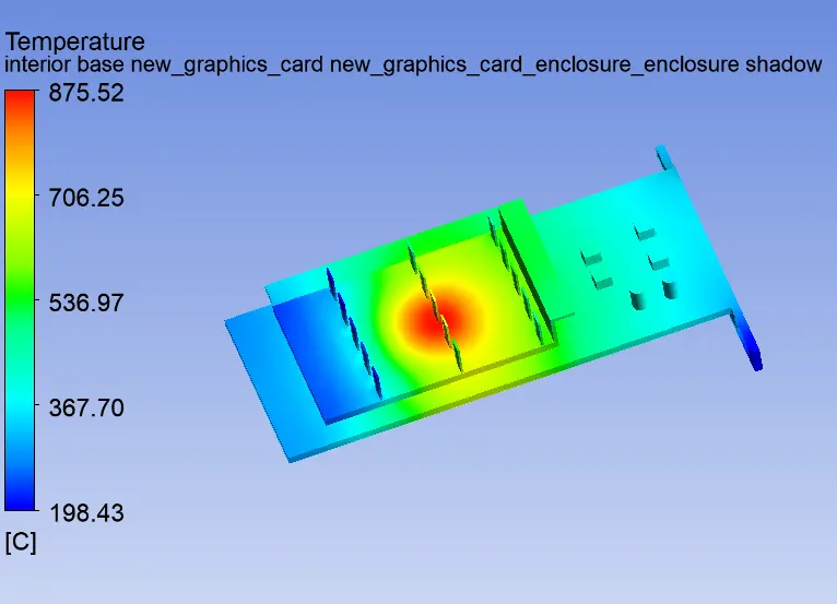
Temperature and wall HT co-efficient of graphic card:
Case 3:
- Inlet velocity 5m/s
- Elemental size for Enclosure 10mm, Fin 5mm , base 3mm, and for processor 0.2mm
- Total number of elements = 267268
Residual plot:
Temperature and wall HT co-efficient of the processor:
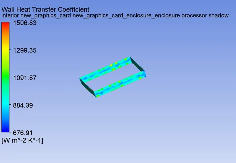
Potential hotspots on the fin and base:
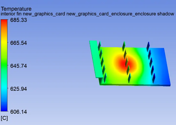
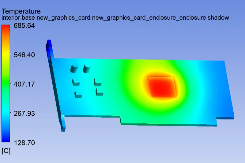
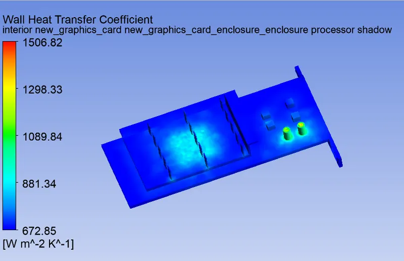
Temperature and wall HT co-efficient of graphic card:
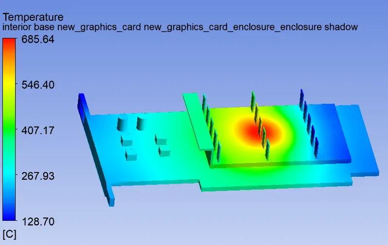
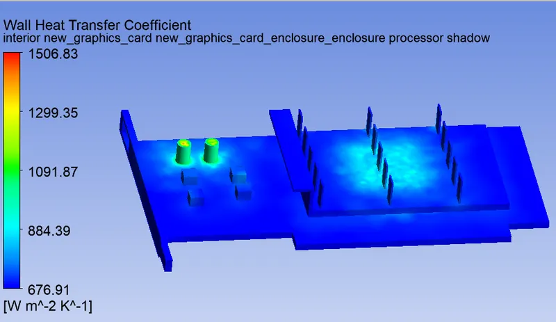
| basemesh | inlet velocity 1m/s(refined case 1) | inlet velocity 3m/s(refined case 2) | inlet velocity 5m/s(refined case 3) | |
| Max temperature of the processor in C | 1627 | 1615 | 879 | 687.7 |
| Wall heat transfer coefficient of processor in `W/(m^2K)` | 583.03 | 1506.82 | 1506.82 | 1506.83 |
Conclusions:
- The refined mesh provides more accurate results compared to the coarse mesh. This accuracy can be increased by increasing the number of mesh elements.
- The temperature of the graphic card assembly decreases with the increase in fluid flow velocity because as the velocity of flow increases, more heat is carried away by it, hence cooling the graphic card.
- The highest wall heat transfer coefficient was obtained near the processor walls, which is `1506.8Wm^-2K^-1`. This region is not affected by the fluid flow, since these walls are in contact with each other and there is no space for air to flow in between them. In the regions which experience fluid flow, the wall heat transfer coefficient increases with the increase in fluid flow velocity.
- The processor is the potential hotspot of the graphic card assembly since it is the only heat-generating part of the entire assembly. The temperature and wall heat transfer coefficients of the processor and other parts are influenced by the heat generated by the processor. Also, the heat generated by the processor depends on its workload. Higher the workload, the higher the heat generated by the processor.