External flow simulation over an Ahmed body(Ansys Fluent)
Objective: To carry out an External flow simulation over an Ahmed body.
Q1. Describe Ahmed's body and its importance.
Answer:
Ahmed's body
- The Ahmed body is a 3D model that is representative of a standard passenger car. It is a research model in order to do experimental analysis and validate it with researched data.
- It is a simplified car body used in the automotive field to study the impact of the flow pattern on drag. The external aerodynamics of the car defines many major traits of the automobile industry like stability, comfort, and fuel consumption at high speed. The flow around the vehicle is characterized by high turbulent and 3D flow separation as well as there is a growing need for more insights into the physical features of these dynamical flows.
- The principle objective is to study this simplified car body in order to tackle the flow processes involved in drag production by perceiving the mechanisms involved in creating drag, one can able to design a car to minimize drag and thereby reducing fuel consumption and maximize vehicle performance.
Importance
- An Ahmed body represents a simplified vehicle volume which helps understand the fundamental physics defining the lift, drag, and coefficients at certain characteristically velocities, pressure differences, seeing and analyzing the vortices, turbulence, and Reynolds number obtained.
- ANSYS is general purposed FEA and CFD simulation software. It gives the numerical prediction of the behavior of a system. This numerical prediction needs to be validated by experimental data. People working on vehicle aerodynamics use Ahmed body to validate their numerical model because experimental data is available for Ahmed body from wind tunnel testing. Once the numerical model data is validated, it is used to design new models of cars.
- Its shape is simple enough to allow for accurate flow simulation but it also retains some important practical features relevant to automobile bodies. This model describes how to calculate the turbulent flow field around a simple car-like geometry using the Turbulent Flow model, K-epsilon, and K-omega model. Later either experimentally or computationally it can be recreated with desired geometry to catch up with new research and market trends.
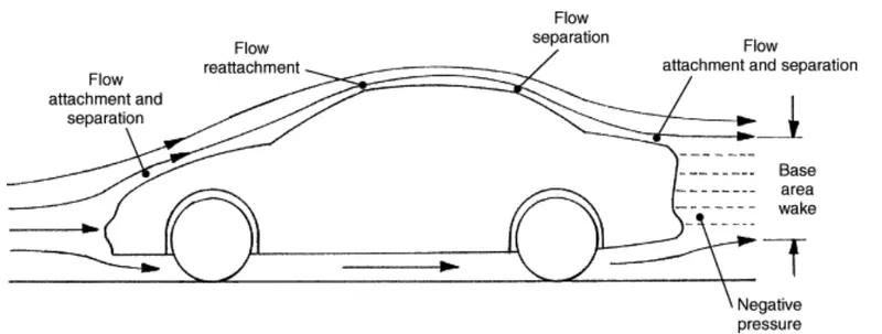
Q2. Explain the reason for the negative pressure in the wake region.
Answer:
- In Fluid dynamics, a wake may either be, The region of recirculating flow immediately behind a moving or stationary blunt body, caused by viscosity, which is accompanied by flow separation and turbulence flow. OR the wave pattern on the water surface downstream of an object in a flow, or produced by a moving object (e.g a ship), caused by density differences of the fluids above and below the free surface and gravity.
- When the vehicle is moving at a certain velocity, the viscous effects in the fluid are restricted to a thin layer called the boundary layer. Outside the boundary layer is the inviscid flow, this fluid flow imposes pressure force on the boundary layer. When the air reaches the rear part of the vehicle, the fluid gets detached. Within the boundary layer, the movement of the fluid is totally governed by the viscous effects of the fluid. The fluid moving around the vehicle is dependent on the shape of the vehicle and the Reynolds number.
- When the air is moving over the vehicle it is separated at the rear end, which leaves a large low-pressure turbulent region behind the vehicle known as the wake. This phenomenon is known as the 'Wake' of the vehicle. This wake contributes to the formation of pressure drag, which eventually reduces the vehicle performance.
- Atmospheric air tries to fill the low-pressure region thus creating the region of vorticity. This also results in the huge pressure gradient in the region exactly rear of the body creating negative pressure in the wake region.
Q3. Explain the significance of the point of separation.
Answer:
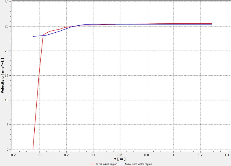
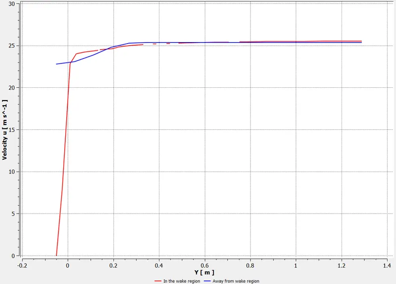
- The fluid separation point can be defined as a point where the du/dy i.e, the gradient of velocity goes zero along with the dp/dx=0 for a specific point. In a more simplified term, we can say that at the point where the velocity gradient goes zero and the pressure gradient along x-direction goes zero the point of separation starts occurring.
- The point of separation cannot be understood just by a single contour in a fast way, it can be supportively studied with the help of the dp/dx plots or velocity plots w.r.t the Y direction and other such plots in which we can see the nature of such physical properties like dp/dx=, and du/dy= experiencing in a particular region of fluid and body interaction
PROCEDURE:
Geometry Set-up:
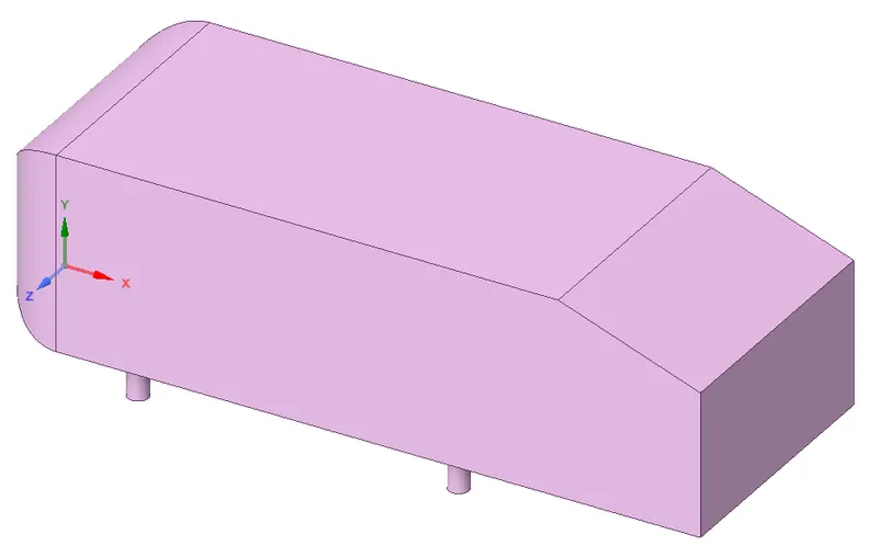
1. Load the Ahmed body in Spaceclaim and convert the units into meters.
The geometry of Ahmed body is shown below:
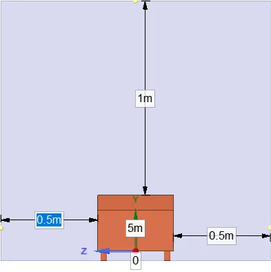
2. Go to prepare and select on the enclosure and select Ahmed's body. Enter the dimension as shown below:

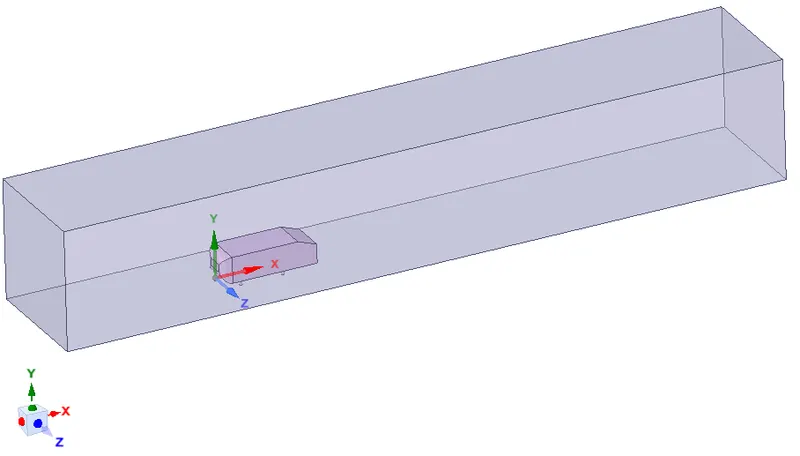
3. Once the enclosure is done, we create another enclosure closely around the Amhed body so that we can refine the mesh in that enclosure and still keep the total cell count in a specific range.

Ahmed body with the inner and outer enclosure
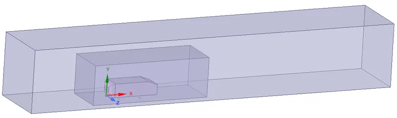
4. After both the enclosure is created, we can check interference and avoid the mesh overlapping by applying check interference and deleting the overlap region. This is automatically done in Spaceclaim when the interference option is selected.
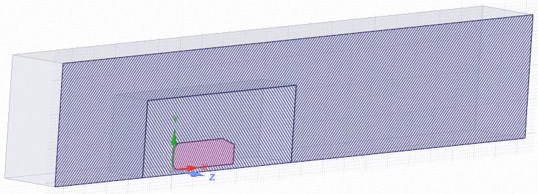
5. After clearing the interference, we can split the body in half using the split body command. After achieving the split, hide the Ahmed body, suppress the physic and go the properties, and select share topology. Now we can mesh both the enclosure and share information.
Fluent Set-up:
- Update the mesh before opening the fluent setup and then perform a meshed check.
- Take the K-epsilon turbulence model.
- Consider pressure-based solver as mach no. is less than 0.3.
- Input inlet velocity 25 m/s.
- Initialize the solution.
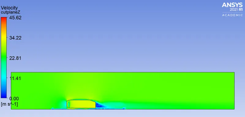
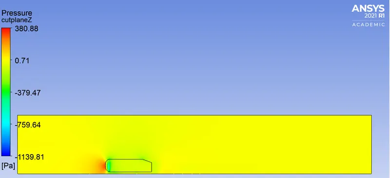
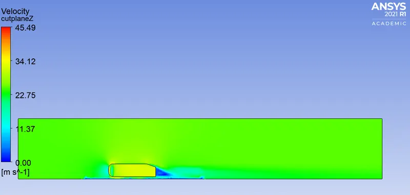
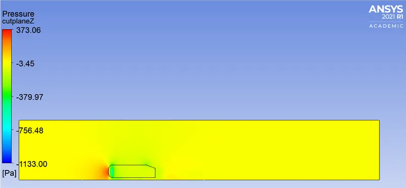
- After initialize we should go to the post process to create a cut plane to see the velocity and pressure plots. And then create a contour plot for both pressure and velocity.
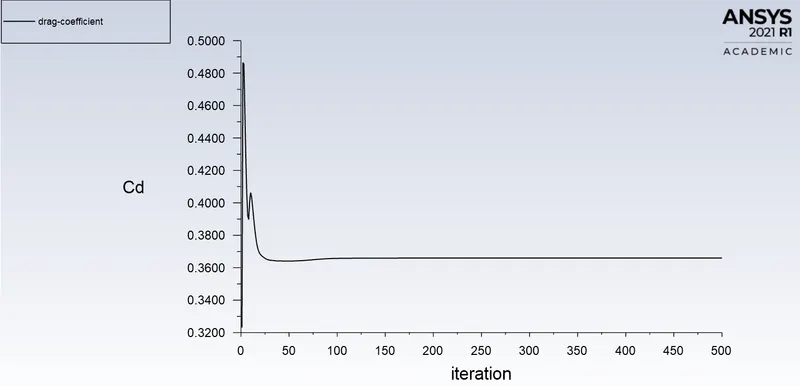
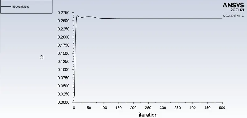
- Create a plot for Drag and lift.
- Give Reference values for the Ahmed body.
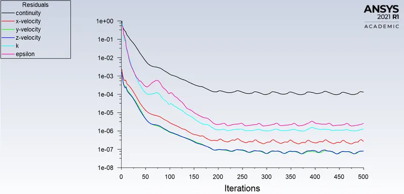
- Run the simulation for 500 iterations.
CASE 1:
Outer Enclosure: 100mm(Elemental size)
Inner Enclosure: 50mm(Elemental size)
Face Sizing for Ahmed body: 5mm(Elemental size)
Inflation layer for Ahmed body: 5 layers with a total thickness of 12.4mm.
Total Cell count: 90423
RESULTS:
1.Residual Plot
2. Velocity and Pressure Contour:
3. Drag and Lift Coefficient
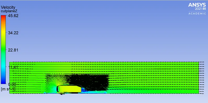
4. Vector Plot
5. Velocity Variation
CASE 2:
Outer Enclosure: 90mm(Elemental size)
Inner Enclosure: 40mm(Elemental size)
Face Sizing for Ahmed body: 5mm(Elemental size)
Inflation layer for Ahmed body: 5 layers with a total thickness of 12.4mm.
Total Cell count: 144269
RESULTS:
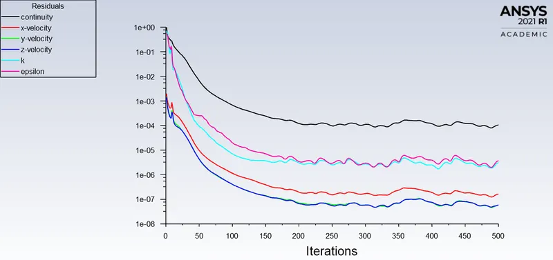
1.Residual Plot
2. Velocity and Pressure Contour
3. Drag and Lift Coefficient
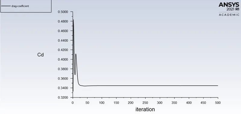
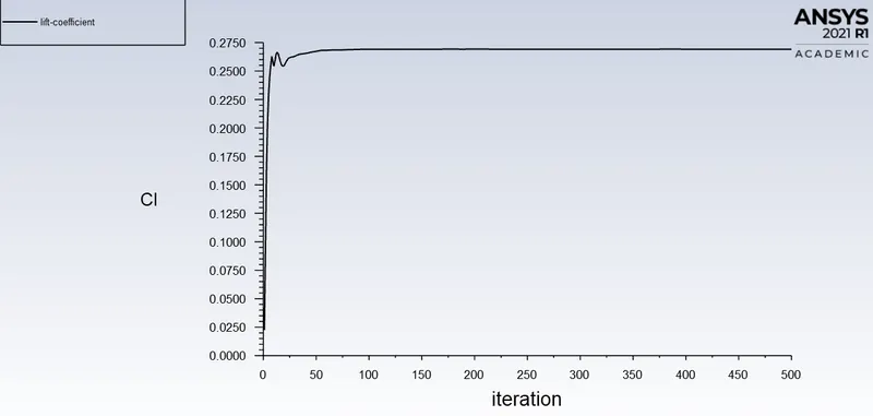
4. Vector Plot
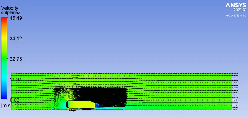
5. Velocity Variation
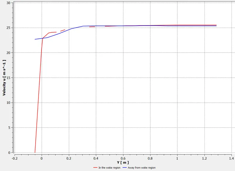
CASE 3:
Outer Enclosure: 80mm(Elemental size)
Inner Enclosure: 30mm(Elemental size)
Face Sizing for Ahmed body: 5mm(Elemental size)
Inflation layer for Ahmed body: 5 layers with a total thickness of 12.4mm.
Total Cell count: 293876
RESULTS:
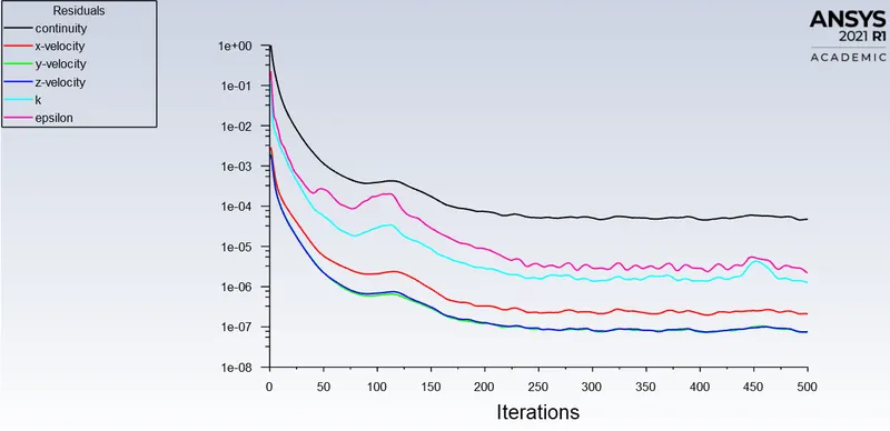
1.Residual Plot
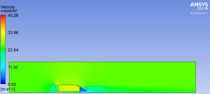
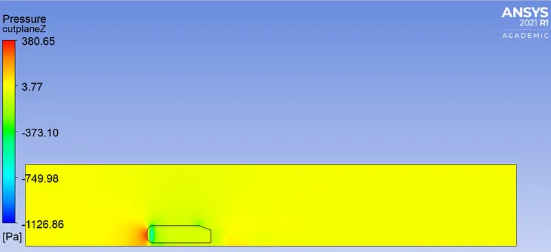
2. Velocity and Pressure Contour
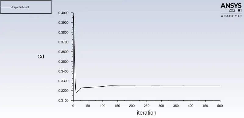
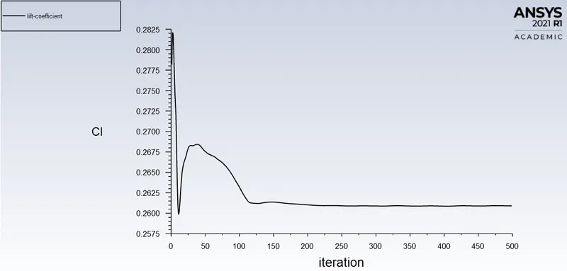
3. Drag and Lift Coefficient
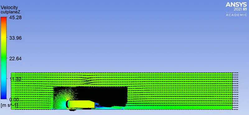
4. Vector Plot
5. Velocity Variation
Grid Independency Test:
From the below table with the refinement of mesh drag coefficient approaches closer to analytical value. This is because more cells are assigned at the boundary layer which results in a more accurate result of the drag coefficient.
| No. of Cells | `C_d` | `C_L` | |
| CASE 1 | 90423 | 0.365 | 0.256 |
| CASE 2 | 144269 | 0.345 | 0.269 |
| CASE 3 | 293876 | 0.325 | 0.260 |
Conclusion:
- High Pressure is formed at the frontal area of the Ahmed body due to the loss in kinetic energy of air.
- The adverse pressure gradient is created near the wake region because of flow separation which occurs because of the geometry of the model.
- With an increase in mesh size, the numerical results approach closer to experimental results.
References:
- https://www.simscale.com/docs/validation-cases/aerodynamics-flow-around-the-ahmed-body
- https://www.researchgate.net/publication/330383775_Experiments_and_numerical_simulations_on_the_aerodynamics_of_the_Ahmed_body
- https://www.researchgate.net/publication/266883948_Flow_and_Turbulence_Structures_in_the_Wake_of_a_Simplified_Car_Model_Ahmed_Model
- https://skill-lync.com/knowledgebase/solvers-in-ansys-fluent
- https://skill-lync.com/knowledgebase/boundary-layer-y-plus-wall-functions-in-turbulent-flows-2