2 D Meshing Of an Automobile Hood using ANSA
2 D MESHING OF AN AUTOMOBILE HOOD USING ANSA
AIM:-
- To check for Geometry errors in the given model and do geometry cleanup.
- To Extract all the Mid surfaces of the given component.
- To Mesh all the Components of the given Model as per the given quality criteria and to get Better Mesh flow in all the Components and Finally giving Thickness to the component.
THEORY:-
The Hood is the hinged cover over the engine of motor vehicles. Hood is also called a bonnet. It is the main component of Front portion The shape of Hood is made aerodynamic to minimize the air resistance. It is used to access the parts like radiator, engine and many parts.
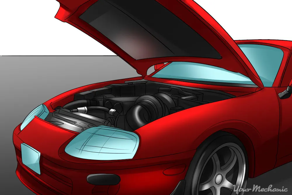
A Hood Consists of Four Parts namely:-
- Outer Panel ( or) the outer cover, It is the outer skin of the inner panel.
- Inner Extract
- Latch Reinforcement
- Hinge Reinforcement
Procedure:-
1.IMPORTING THE CAD MODEL AND GEOMETRY CLEANUP
- First, we open ANSA software and then we import the CAD model using the FILE ~ OPEN
- Disassemble the model into Outer Extract, Inner Extract, Hinges and Latch
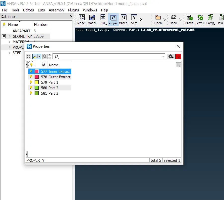
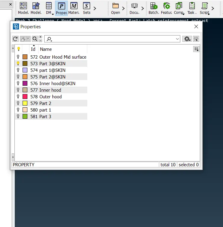
- Change the name of the existing PIDs to Outer Extract, Inner Extract, Part 1, Part 2 ( Hinges) and Part 3 ( Latch) and create Lock views for every Component.
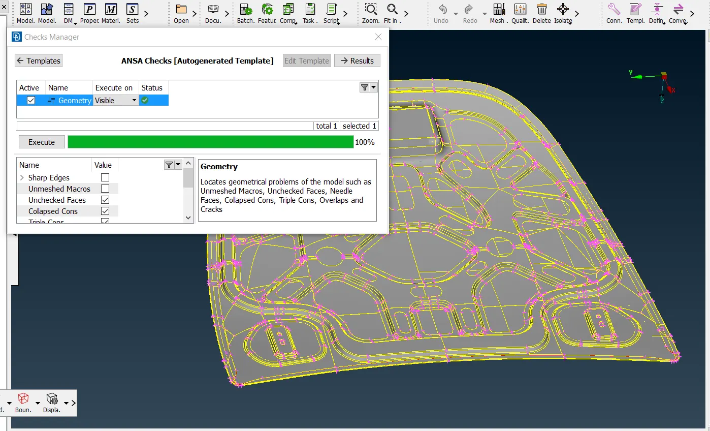
- Apply the Topo and Checkup for the Geometry errors using Checks ~ Geometry
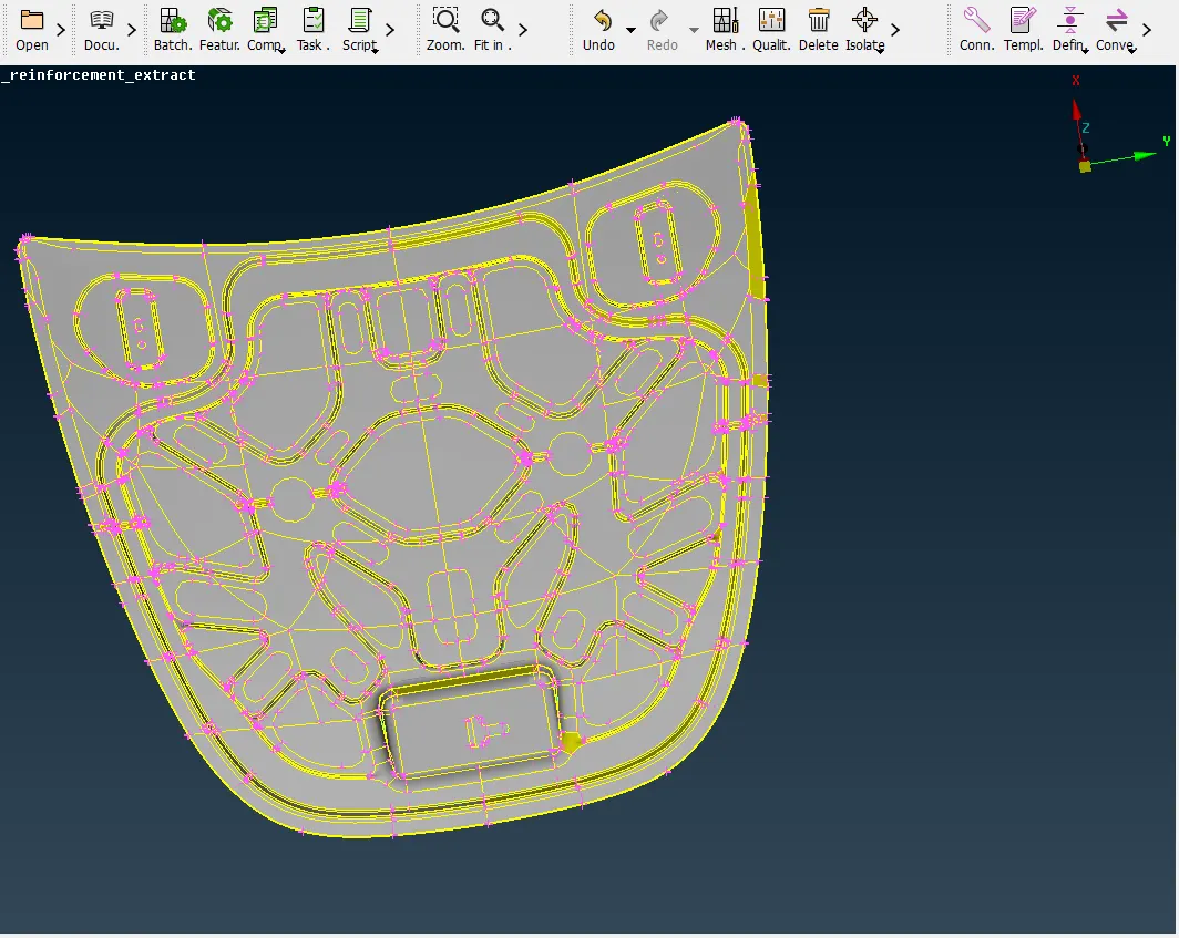
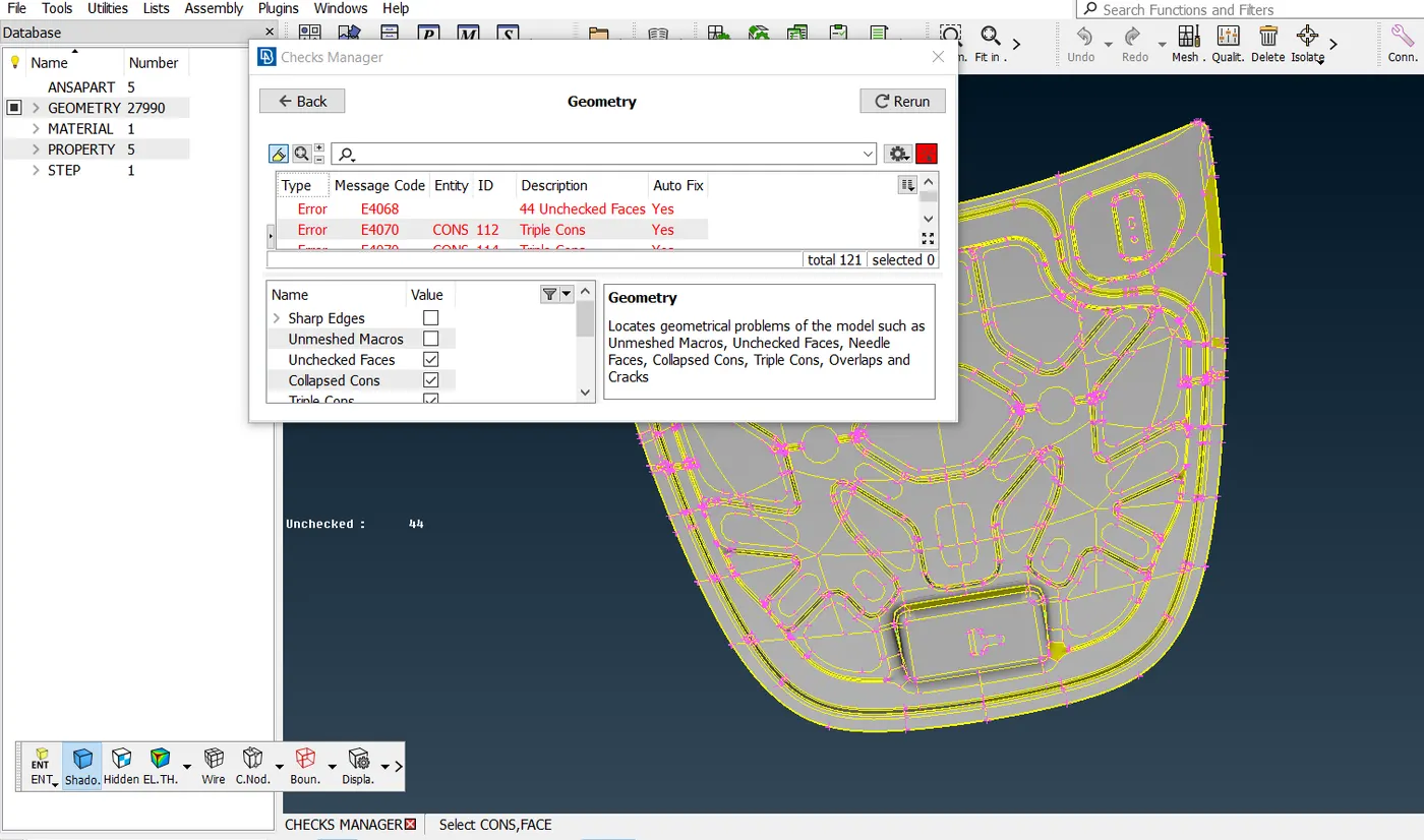
- Correct all triple cons using Release option in the Cons section and Topo option in Faces section under Topo module
- Needle Faces, Crack Between the cons can be removed using Fix option.
- It is made sure that all the geometry errors were cleared before going to Mid- Surfacing.
2.MID SURFACING:-
- Mid-surface can be obtained manually and automatically.
- It can be obtained manually by using the OFFSET ~ Faces option in the Faces section.
- It can be obtained automatically by using MID SURFACE ~ SKIN option in the Faces section.
- If the Mid surface is generated automatically then the PID is created automatically for the Mid surface.
- But if the MId surface is generated manually then the PID must be set manually, this can be done using SET PID option in the Faces section.
- Here the Mid surfaces are generated automatically for all the components except Outer Extract.
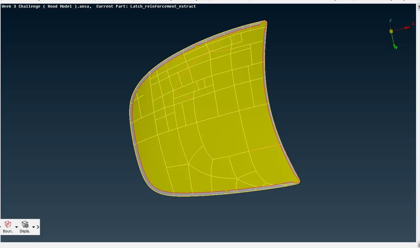
- Outer Extract Mid surface is generated manually using OFFSET ~ Faces option in the Faces section and PID is set manually using SET PID
- After generating mid surface, Geometry check was done and made sure that no errors were there before going to Meshing.
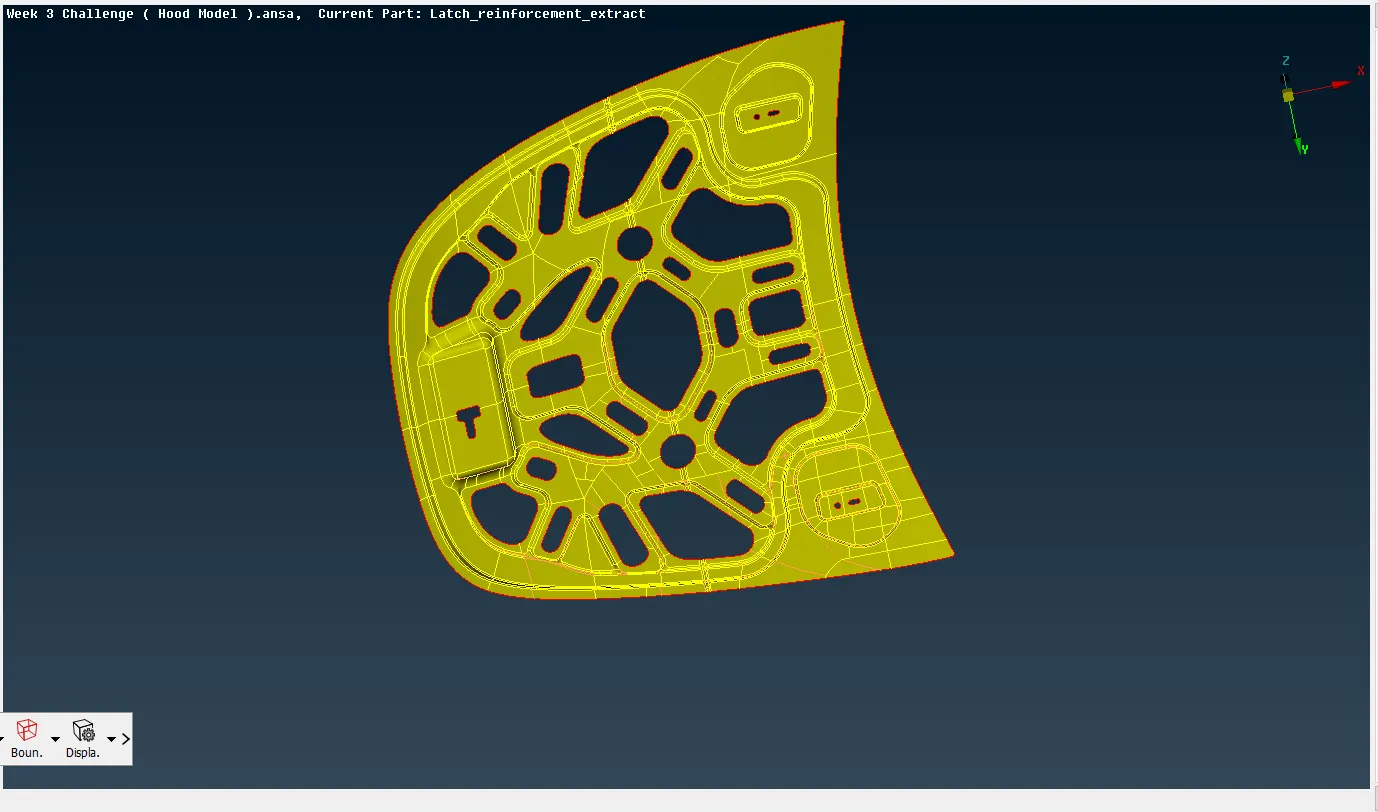
INNER EXTRACT MID SURFACE:-
OUTER EXTRACT MIDSURFACE:-
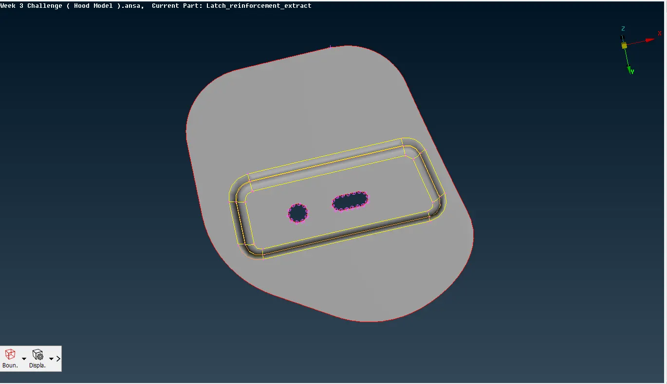
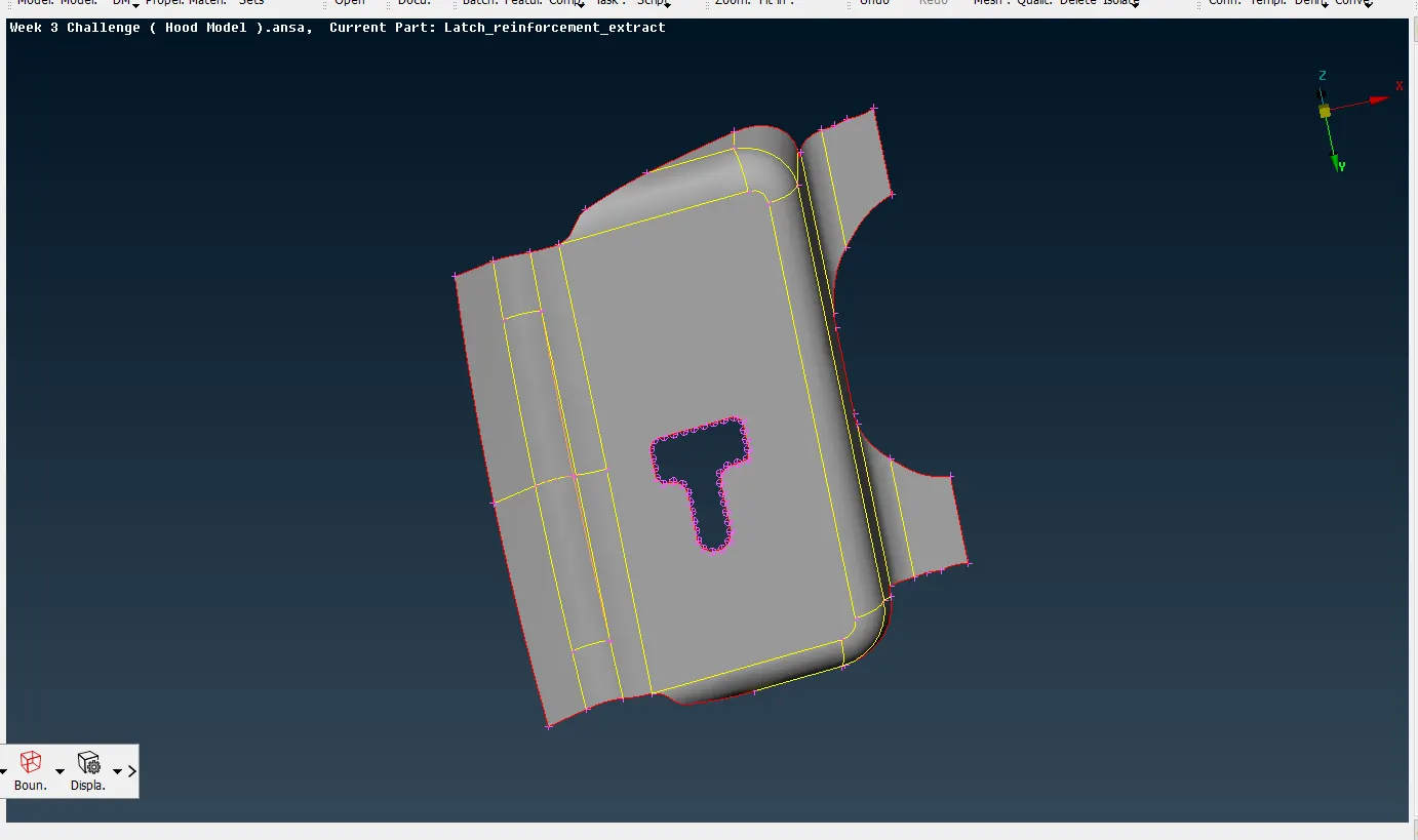
HINGES AND LATCH MIDSURFACES:-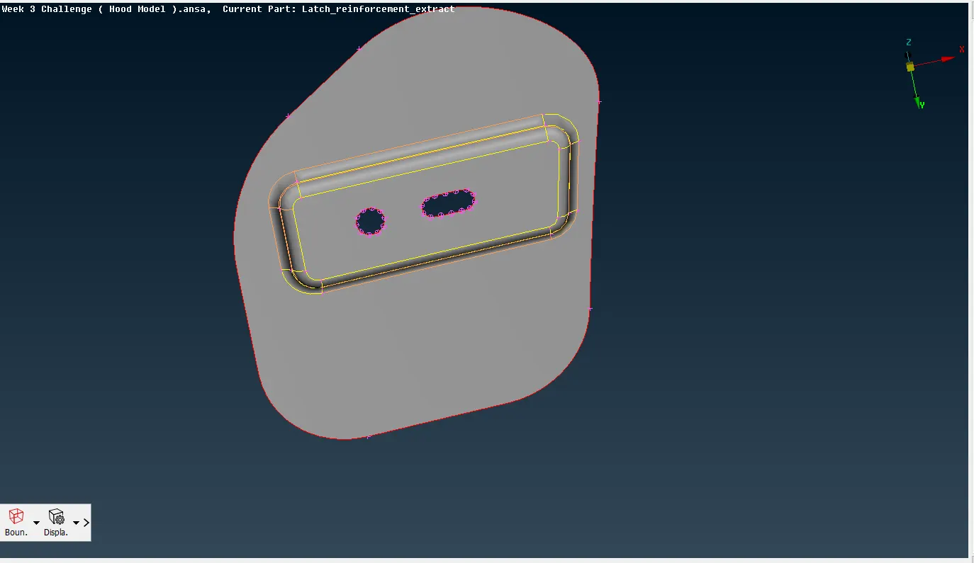
3.MESHING:-
- .Before we do Meshing, we need to set the Quality Criteria in the aim to get good quality mesh. To do this, Go to UTILITIES bar and click on the QUALITY CRITERIA option, and then required quality parameters are entered as per the given problem and in the presentation parameters, the elements check is ticked.
- we then specify the average (or) target element length and min length and max length of the mesh using the MESH PARAMETERS option in UTILITIES toolbar.
- For meshing, the element size must be consistent, for this go to PERIMETERS ~ LENGTH, and enter the value as 5.
- In 2D Meshing, the meshing is done on the mid surface.
- Before doing meshing, For holes present in the model, It is made sure that holes have even number of edges using PERIMETERS ~ NUMBER
- And the holes are Slid using PERIMETERS ~ SLIDE and made sure that holes edges are slid in such a way that they are parallel to the nearest edges of the model.
- All the Fillets are checked before meshing to make sure that it is under the minimum length given for Meshing.
- Mesh is done on the model using the BEST option in the MESH GENERATION section.
- CUT option From MACROS section is used to cut the surface according to the way of Meshing
- Quality failed elements must be cleared using RECONSTRUCT option in SHELL MESH section and SPLIT, SWAP, JOIN options in ELEMENTS section. ( In the image given below, the elements are failing in quality in Jacobian, Warping, Max.length and Angle )
- Trias must be reduced to get better mesh flow, this is done using the PASTE option in GRIDS section, SPLIT, SWAP, JOIN options in ELEMENTS section and SMOOTH option in SHELL MESH section. ( Quality failed elements were cleared and trias are reduced as shown in the image given below )
- Inner Extract mid surface, Outer Extract mid surface are symmetrical parts, so the mesh can be done in half of the model and then half of the mesh can be copied to the other half using TRANSFORM COPY and using SYMMETRY.
INNER EXTRACT MESHING:-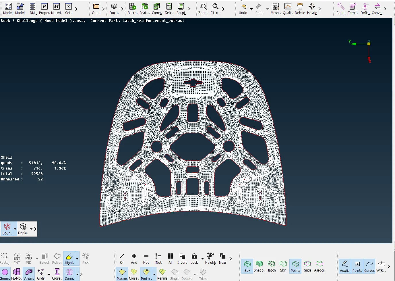
OUTER EXTRACT MESHING:-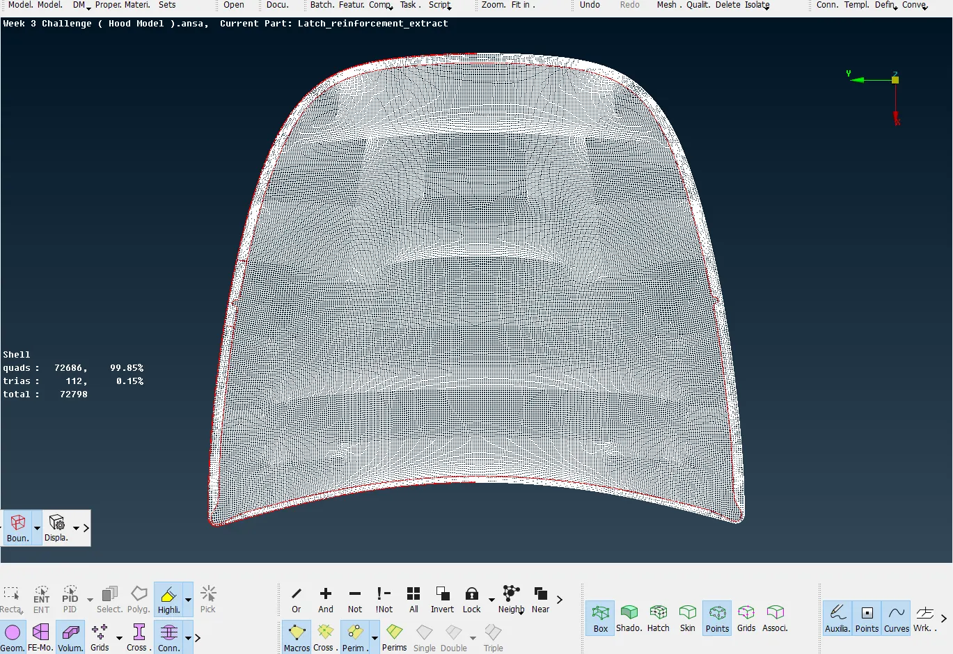
HINGES AND LATCH MESHING:-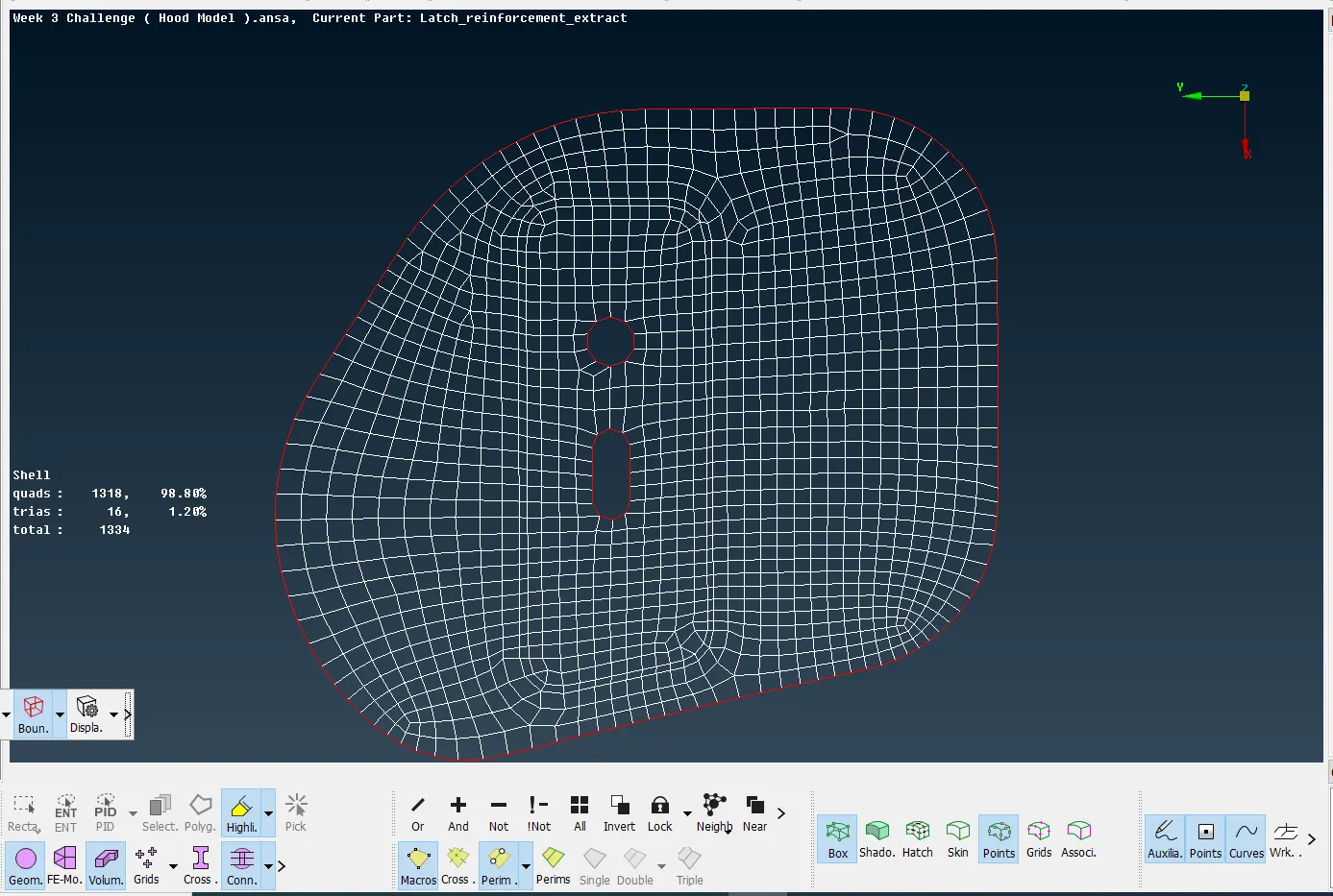
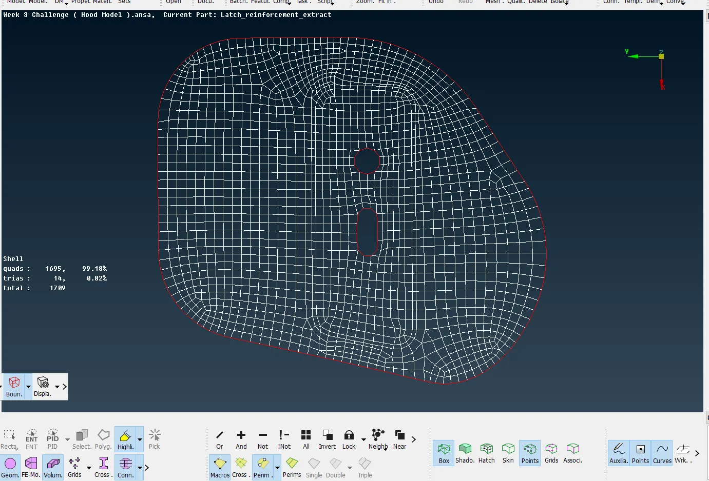
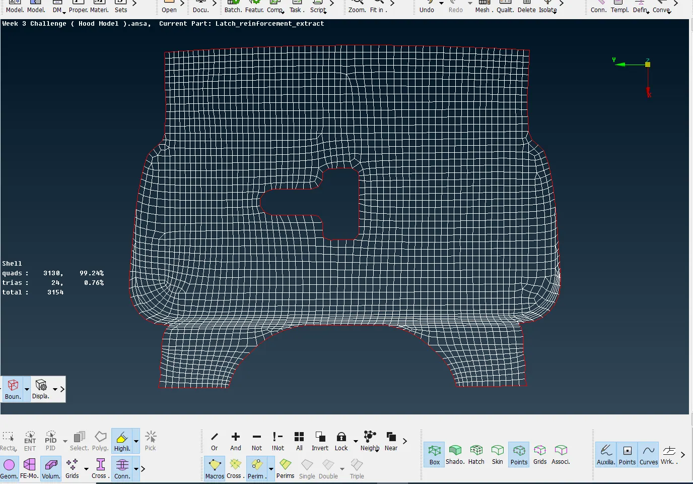
FINAL COMPONENT:-
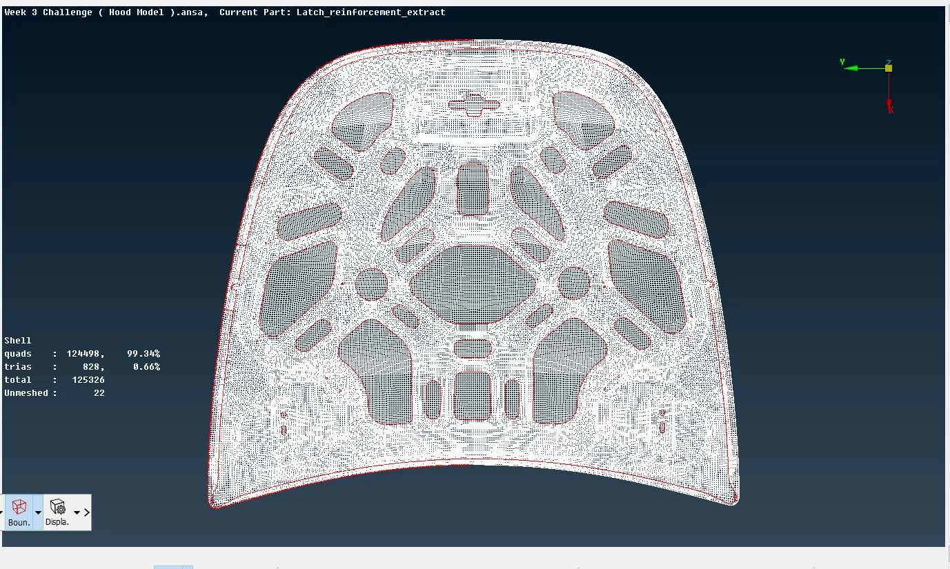
Finally we have to give the Thickness to the meshed Component therefore, we go to the utilities toolbar and click on Quality Criteria Option and then dialog box opens as shown in the image below, In that the Presentation Parameters is Clicked and the draw shell as solid Check box is ticked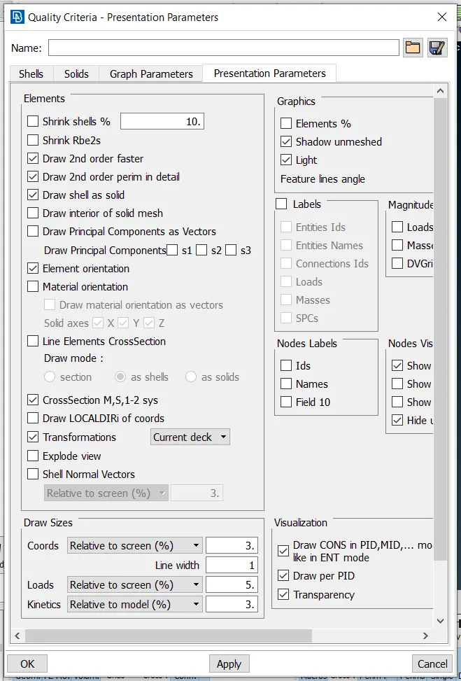
CONCLUSION:-
The given model was checked for geometry errors and mid surface was generated using both manual and auto mid options. The component was meshed and the max.quad percentage was found to be 99.34% and max. trias percentage was found to be 0.66% Finally, the model was assigned a thickness using draw shell as solid in the quality parameter dialog box.
LEARNING OUTCOMES:-
- Learned how to perform geometry check and remove geometry errors
- Learned how to generate mid surface both manually and automatically by using some of the options like mid surface and offset.
- Learned how to do meshing and remove quality failed elements using options like Reconstruct, split, swap, Join.
- Learned how to get better mesh flow and eliminate trias using options like split, swap, Join, paste, smooth and Reconstruct.