2D MESHING OF BOTTLE CAP USING ANSA
2D MESHING OF BOTTLE CAP USING ANSA
AIM:-
To Successfully extract the mid surface and mesh the given Bottle cap model with the given Quality Criteria and to get good mesh flow in the model.
Procedure:-
1.IMPORT THE CAD MODEL AND GEOMETRY CLEAN UP
- First, we open ANSA software and then we import the CAD model using FILE ~ OPEN
- After Importing the CAD model, Topo was given to the entire Component
- Geometry was refined by Changing the length of elements to 1mm. Do this by using the Length option under Perimeters in the Mesh module
- Check for the geometry errors in the model by using the CHECKS ~ GEOMETRY under the Tools menu. and clear all the geometry errors.
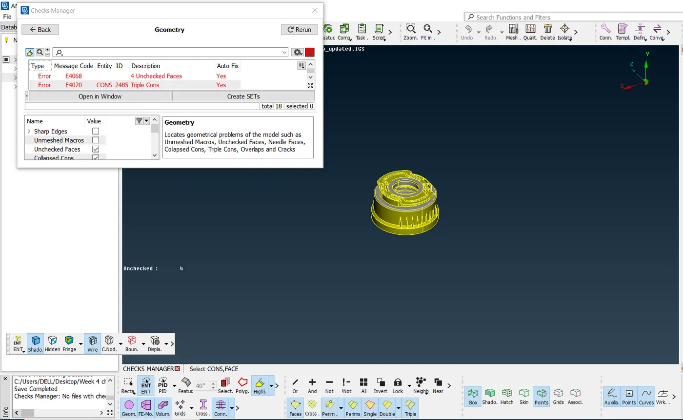
FIG 1. Geometry errors present in the model 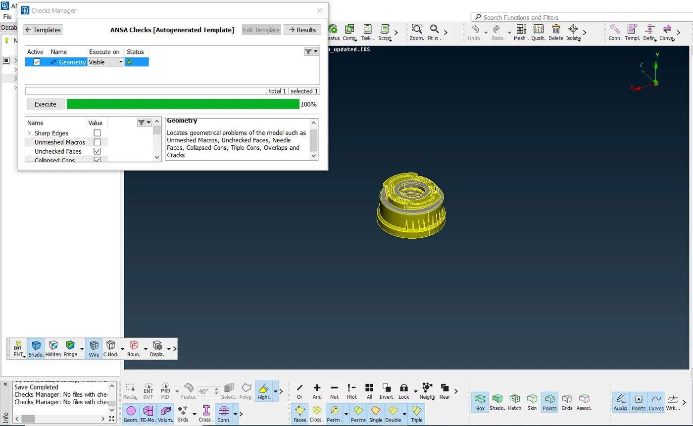
Fig 2. After clearing all the Geometry errors in the model
2.MID SURFACING:-
- . Mid surface can be obtained both manually and automatically
- But in the Present model, Manual mid-surfacing was chosen to generate the mid-surface, due to the complexity in the geometry.
- Mid-surfaces were generated by using the Faces~ Middle option and Offset option in the Topo module.
- At some regions, MId surface was generated using Curve~middle option and the new surface is created using Faces ~ New ~ Coons option in the Topo module.
- To generate Mid-surface for Threads, Curve ~ middle option is used to generate the curve and that curve is projected on to the surface using CONS ~ project and the New surface is created using Faces ~ New ~ Coons option
- To generate Mid-surface for Teeth, Curve ~ middle option is used to generate the curve and the CONS ~ Project is used to project the Con to the Base mid surface and the New surface is created using Curve and con by Faces ~ New ~ Coons option, Since we have 36 teeth, Transform ~ Copy ~ Rotate option is used to generate mid surface for other Teeth.
- Necessary extensions were made using the Extend ~ Target option under Faces in the Topo module.
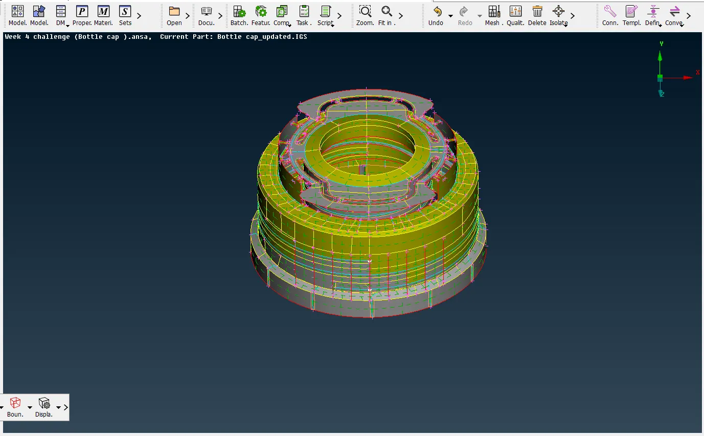
FIG 3. Mid surface of the Bottlecap model
3.ASSIGNING PIDS TO THE MIDSURFACE:-
Since Bottle cap model is a plastic component, it will have Features with Different thickness, each and every individual feature of the model was given own identity by assigning their respective thickness values by creating PIDs as shown below. PIDs were set using the SET PID option in the Faces Section of the Topo Module.
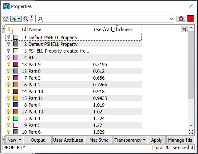
FIG 4. PIDS of the Bottlecap Model
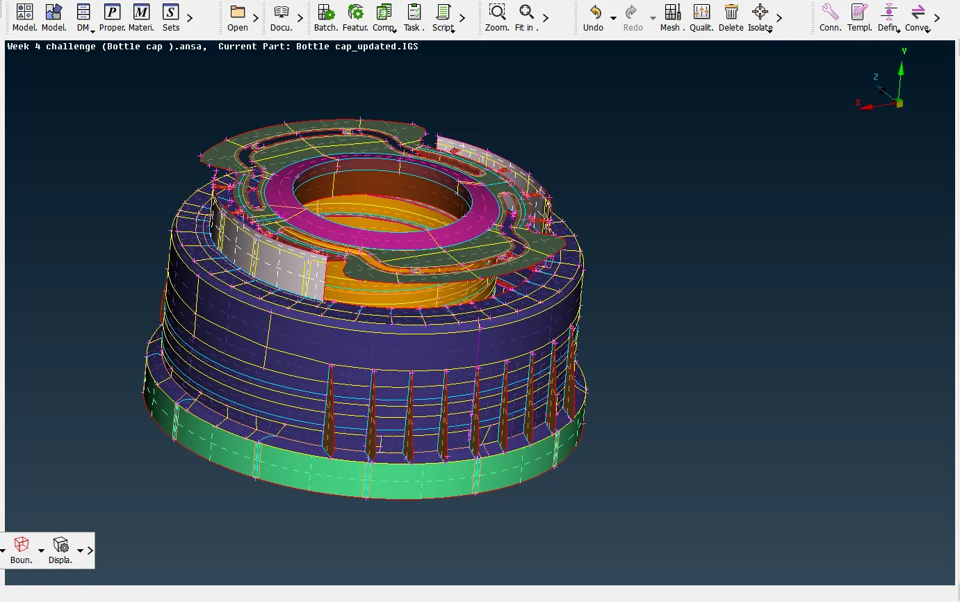
FIG 5. Mid surface of the Bottlecap model ( After assigning Pids )
4.MESHING:-
1.Before we do Meshing, we need to see the Quality criteria in the aim to get good quality mesh. To do this, Go to UTILITIES bar and click on the QUALITY CRITERIA option, and then required quality parameters are entered as per the given problem and in the presentation parameters, the elements check is ticked.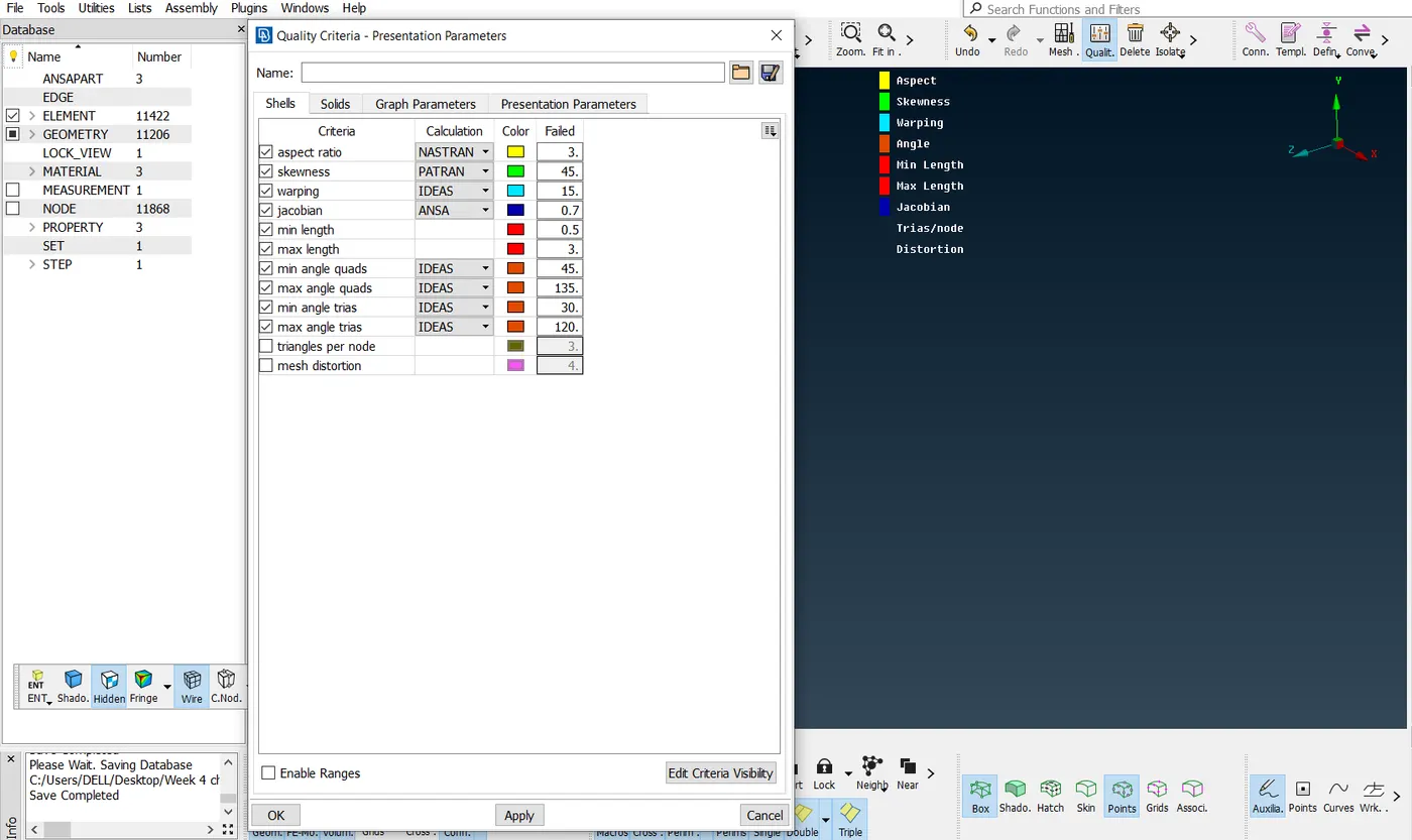
FIG 6. Quality Criteria ( as per given in the Problem )
2.we then specify the average (or) target element length and min.length and max.length of the mesh using the MESH PARAMETERS option in the UTILITIES toolbar.
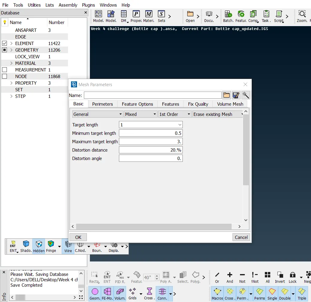
FIG 7. Mesh Parameters
3.For meshing, the element size must be consistent, for this go to PERIMETERS ~ LENGTH, and enter the value as 1.
4. CUT option from MACROS is used to cut the surface according to the way of Meshing.
5. Mesh is done on the model using the BEST option in the MESH GENERATION Section.
6.Trias must be reduced to get Better mesh flow, this is done using the PASTE option in GRIDS Section, SPLIT, SWAP, JOIN option in ELEMENTS Section and SMOOTH option in SHELL MESH Section.
7.Quality failed elements are reduced as much as possible using RECONSTRUCT option in SHELL MESH section and MOVE option in GRIDS Section.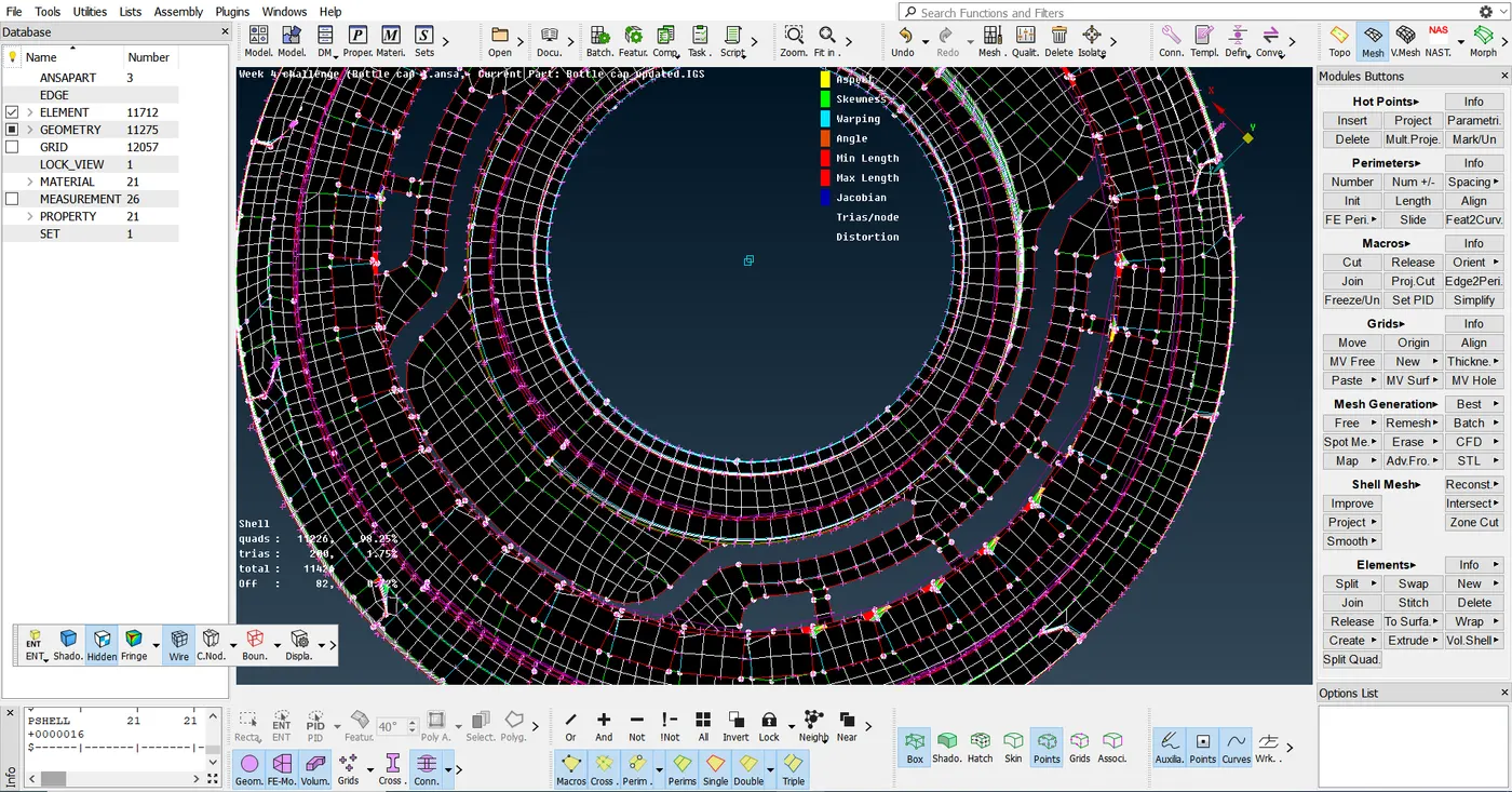
FIG 8. Quality failed elements Present in the model
8.The Quality failed elements Could not be cleared at Few regions Because of Triple cons Present over there.
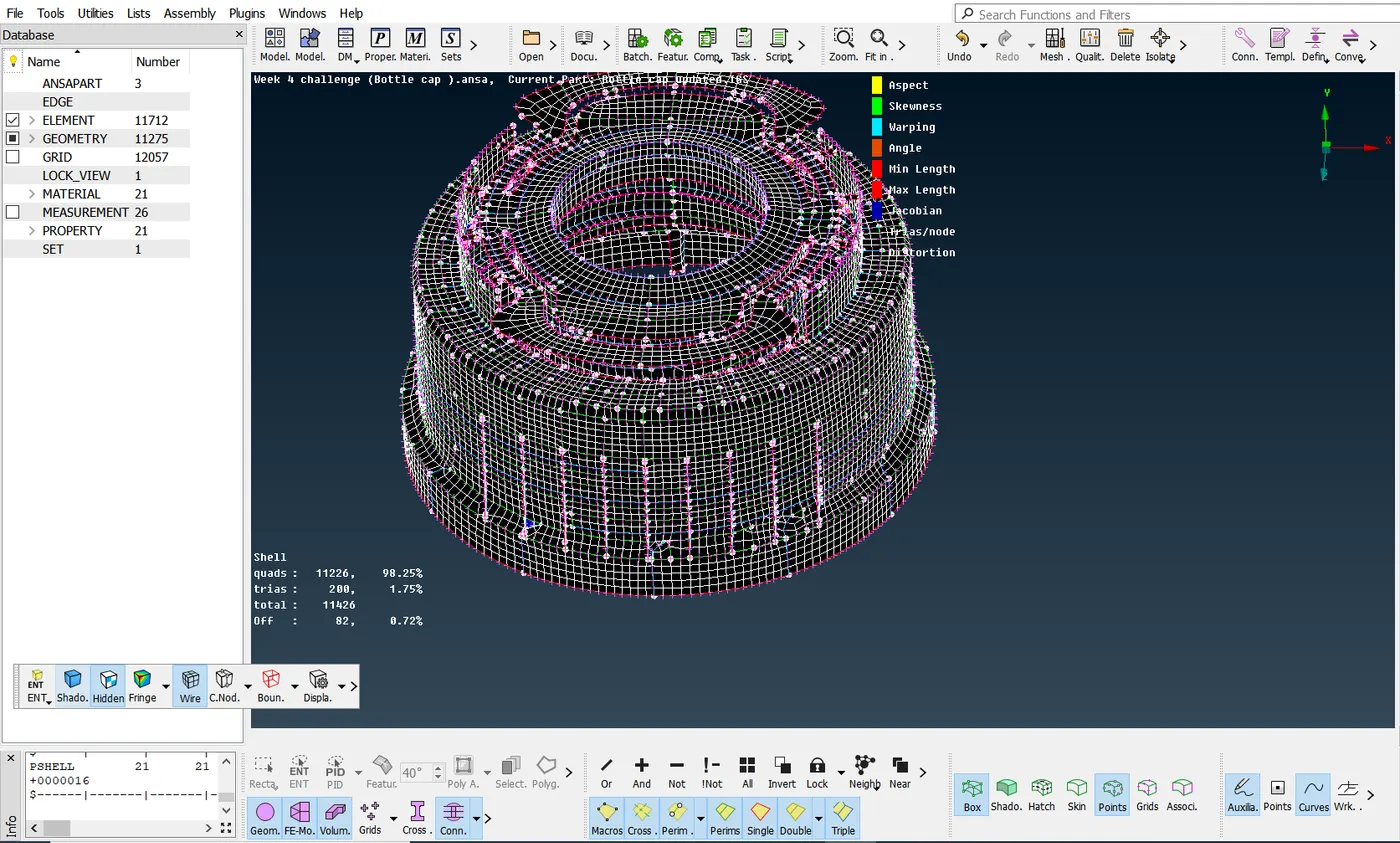
FIG 9. Mid surface of the Bottlecap model (After Meshing )
Finally, we have to give the Thickness to the Meshed Component therefore, we go to the Utlities toolbar and click on Quality criteria option and then dialog box opens as shown in the image below, In that the Presentation parameters is clicked and the Draw shell as solid Check box is ticked.
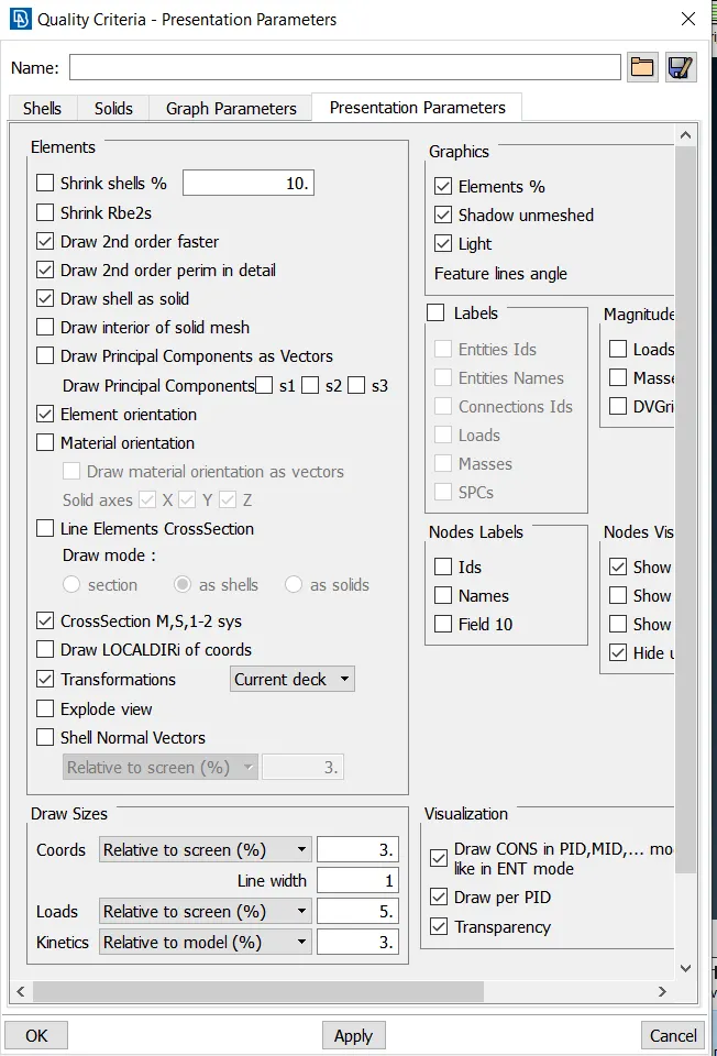
FIG 10. Applying Draw shell as solid to the model.
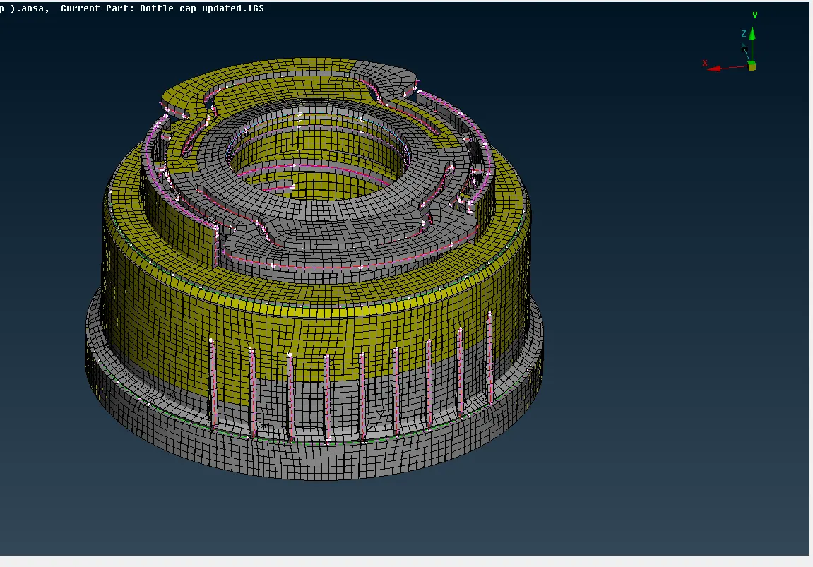
FIG 11. Bottlecap model ( After applying Draw shell as solid to the model )
CONCLUSION:-
The given model was checked For geometry errors, and geometry errors were cleared, Mid surface was extracted manually, The PIDs for features are set with proper thickness, the Component was meshed and Max.quad percentage was found to be 98.25 %, Max. tria percentage was found to be 1.75 % and Quality Failed ( off ) elements percentage was found to be 0.72 %, Finally the model was assigned thickness using draw shell as solid in the Quality Parameter dialog box.
LEARNING OUTCOMES:-
1. Learned How to extract proper mid surface for a model with varying Thickness.
2. Learned how to take mid surface using Commands like Faces ~ middle, Curve ~ middle e.t.c.
3. Learned how to extract mid surface for threads and teeth on the component.