Week -2
Aim-
1. To build a Simulink model of Doorbell using solenoid block with the following details:
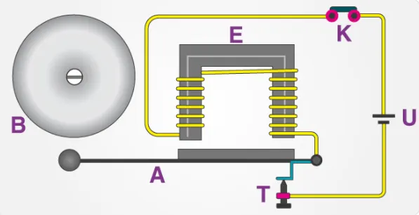
In the above arrangement, when the switch is closed the electromagnet receives electrical power from the battery and pulls the metal arm to hit the bell producing sound. Create a situation where the switch is closed for 2 seconds and then released. Observe the physical movement of the plunger. Assume remaining parameters.
Doorbell- Doorbell is a signaling device typically placed near a door to a building's entrance. When a visitor presses a button and bell rings inside the building, alerting the occupant to the presence of the visitor. Although the first doorbells were mechanical, activated by pulling a cord connected to a bell, modern doorbells are electric, operated by a pushbutton switch. Modern doorbells often incorporate intercoms and miniature video cameras to increase security.
The electric doorbell is a simple circuit that triggers a sound on the completion of circuit by pressing the button. It is this simplicity that makes doorbell such a marvel. The simple devices in the doorbell put the scientific principle of electromagnetism into action in a useful way. In order to understand the operations of an electric bell, you should first need to understand about electromagnets.
Well, an electromagnet is basically a type of magnet in which the magnetic field is produced with the help of an electric current. When any electrical influences electromagnet it works as a standard magnet (generating magnetic fields). When the power generation to an electromagnet stops, the production of the magnetic field also stops. Doorbells get their power from the home's electrical system. The doorbell switch has two terminals that are wired to the doorbell transformer located in the house. The transformer is a metal box with two terminals connected to the doorbell wires.
Process of the working of an electric bell
Now that you have an understanding of the important parts in an electric bell, the step-by-step process of the working of the electric bell is described below:
- The switch is pressed and current flows through the circuit.
- The electromagnet is powered and generates a magnetic field that attracts the iron strip towards it.
- The striker strikes the gong (bell).
- When the striking arm strikes the gong, the contact is broken and current stops flowing through the circuit.
- This causes the electromagnet to lose its magnetic field.
- The connected spring arm returns the striker to its original rest position.
- The contact is restored and current flows through the circuit (provided the main switch is still pressed).
- The process is repeated from the beginning.
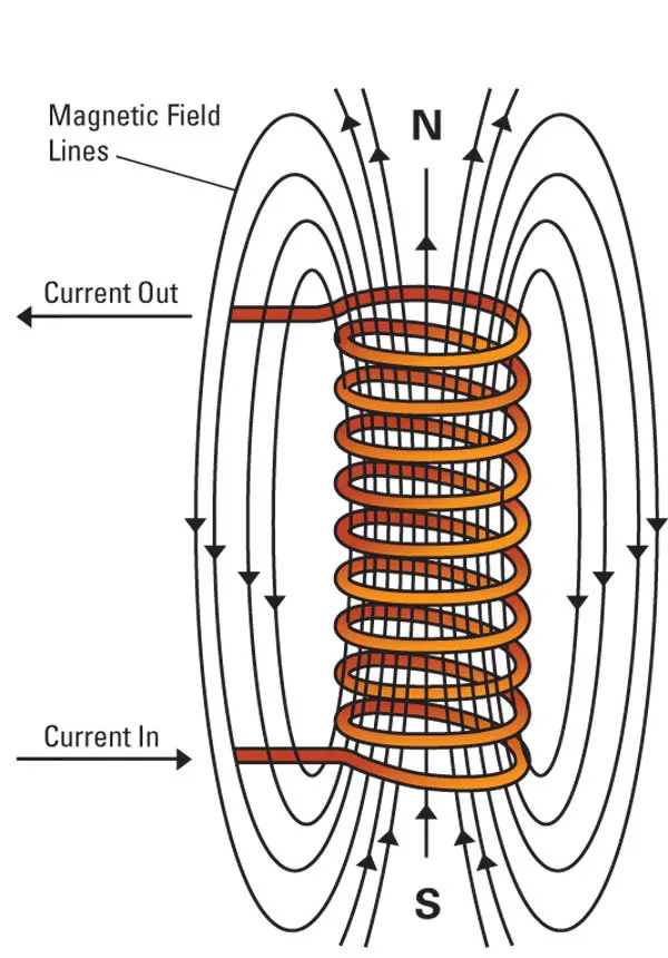
Solenoid- A solenoid is a device comprised of a coil of wire, the housing and a moveable plunger (armature). When an electrical current is introduced, a magnetic field forms around the coil which draws the plunger in. More simply, a solenoid converts electrical energy into mechanical work.
- The coil is made of many turns of tightly wound copper wire. When an electrical current flows through this wire, a strong magnetic field/flux is created.
- The housing, usually made of iron or steel, surrounds the coil concentrating the magnetic field generated by the coil.
- The plunger is attracted to the stop through the concentration of the magnetic field providing the mechanical force to do work.
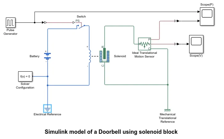
Block used in this Simulink model
1.  Pulse Generator- The pulse generator generates square wave pulses at regular intervals. The shape of the waveform is determined by the block waveform parameters, amplitude, pulse width, period, and phase delay.
2.  Simulink-PS Converter- This block converts the Simulink input signal to a Physical Signal. Before providing input to the circuit, the signal from the source is transformed into a physical signal.
3.  PS-Simulink Converter- It converts the Physical signal to Simulink input signal. It is necessary to transform to Simulink signal before providing it to the display or scope as it only takes simulink singnal as input and conver it into display signal.
4.  Solver Configuration- It defines solver settings to use for simulation.
5.  Switch- The block represents a switch controlled by an external physical signal. If the external physical signal PS is greater than the threshold, then the switch is closed, otherwise the switch is open. The closed resistance is defined by parameter R_closed, and the open conductance is defined by parameter G_open. Both parameters must be greater than zero.
6.  Battery- This block models a battery. If you select Infinite for the Battery charge capacity parameter, the block models the battery as a series internal resistance and a constant voltage source. If you select Finite for the Battery charge capacity parameter, the block models the battery as a series internal resistance plus a charge-dependent voltage source defined by:
V = Vnom*SOC/(1-beta*(1-SOC)), where SOC is the state of charge and Vnom is the nominal voltage. Coefficient beta is calculated to satisfy a user-defined data point [AH1,V1].
7. 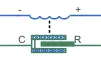 Solenoid- This block implements the electrical and mechanical characteristics of a solenoid. Parameterization is in terms of two points [X1,F1] and [X2,F2] on its force-stroke curve for a 100 percent duty cycle at Rated voltage Vdc and Rated current Idc where X2>X1>0 are stroke values and F1>F2>0 are corresponding forces. The plunger fully in (i.e. air gap closed) corresponds to X=0, and pull-in force is assumed to decrease quadratically with the magnitude of X. To ensure the force remains finite, the following condition should hold: X2/X1>sqrt(F1/F2).
The plunger Maximum stroke is implemented as a hard stop, the dynamics of which are set by the Contact stiffness and Contact damping parameters. The same parameters are used to model the contact dynamics when the plunger pulls fully in. The Spring constant parameter is used to implement a spring force that pulls the plunger out, and can be set to zero.
8.  Electrical Reference- Electrical reference port. A model must contain at least one electrical reference port (electrical ground). A ground connection is essential in an electrical model.
9. Ideal Translational Motion Sensor- This block measures velocity or displacement in a mechanical translational network. The sensor is ideal since it does not account for inertia, friction, delays, energy consumption, and so on.The physical signal ports V and P report the velocity and position, respectively, of port R relative to port C. The measured velocity is positive when the velocity at port R is greater than the velocity at port C.
10.  Mechanical Translational Reference- This block measures velocity or displacement in a mechanical translational network. The sensor is ideal since it does not account for inertia, friction, delays, energy consumption, and so on.The physical signal ports V and P report the velocity and position, respectively, of port R relative to port C. The measured velocity is positive when the velocity at port R is greater than the velocity at port C.This block represents a mechanical translational reference point, that is, a frame or a ground. Use it to connect mechanical translational ports that are rigidly affixed to the frame (ground).
11. Scope- It shows the signal that is generated during simulation. Here 2 scopes are used Scope(P) and Scope(V). Scope(P) displays the position signal from the pulse generator and Ideal transational motion senser whereas Scope(V) displays velocity signal from the Ideal transistional motion sensor.
Explanation for above Simulink model
The switch block is controlled by an Pulse signal as an external physical signal input, and if the external physical signal is larger than zero, the switch is closed, otherwise the switch is open. The positive terminal is linked to the positive terminal of the solenoid block, whereas the negative terminal is linked to the solver configuration and electrical references and the circuit is closed. We create a full electrical circuit by connecting the solenoid block to the switch and battery. The mechanical reference is linked to the common connection C. To monitor the movement of the plunger, the ideal translation motion sensor is linked to the solenoid block R. To obtain the output, the scope is further linked to the ideal translation sensor. The pulse generator signal was converted using the Simulink Ps converter and sent into the input switch. The voltage of the linked battery was set to be the same as the rated voltage of the solenoid(here we used 12 V). The switch is linked to the same circuit as well. An ideal translation motion sensor linked to the circuit measures the position of the solenoid plunger. The scope is linked in order to visualise its behaviour. To produce the required graph, the spring constant and damping value of the solenoid block were changed accordingly.
Result
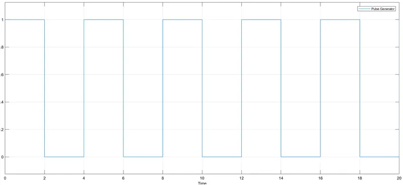 Input signal from Pulse Generator (input position signal)
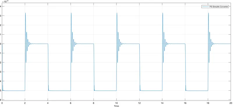 Output Signal (Output position signal or signal from plunger motion)
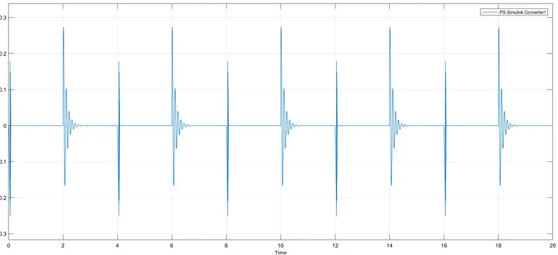 Output velocity signal
Conclusion
Giving the pulse generator input as a time interval of 2 seconds to open and close the switch. When the switch is closed, the solenoid, block, and plunger receive electricity from the battery and move from connection R to connection C, striking the bell and producing sound. The physical movement of the plunger is detected using a translational motion sensor, and the physical output is transformed into a Simulink output model, which is presented in the scope.
Note- We can decrease the oscillation or vibration of the plunger by lowering the spring constant(stiffness) and raising the damping value.
2. Use a thermistor to sense the temperature of a heater & turn on or turn off the fan as per below conditions:Temperature source: 20 °C from 0 to 10 seconds, 27 °C from 10 to 30 seconds, 23 °C from 30 to 50 seconds. Fan conditions:- ON if the temperature above 25 °C, OFF otherwise.
Main Objective-
- To generate a wave of temperature coefficient using suitable block.
- To obtain the characteristics curve for change in voltage w.r.t time.
- To control a DC motor for a given condition
Theory
Thermister- A thermistor is a resistance thermometer, or a resistor whose resistance is dependent on temperature. The term is a combination of “thermal” and “resistor”. ... When temperature increases, the resistance increases, and when temperature decreases, resistance decreases. This type of thermistor is generally used as a fuse. The principle obeyed by the thermistor is its dependency on-resistance values on the change in temperature. The value of resistance can be measured by using an ohmmeter. These are connected in series with the battery and the meter.
The main two types of thermistors are NTC (Negative Temperature Coefficient) and PTC (Positive temperature coefficient).
Thermistors are typically made of semiconductor materials that have been selected due to their temperature-dependent resistance change. These materials usually consist of a mixture of different oxides of metals such as cobalt, copper, magnesium, manganese, titanium, and nickel or doped ceramics. Thermistors are used as temperature sensors. They can be found in every day appliances such as fire alarms, ovens and refrigerators. They are also used in digital thermometers and in many automotive applications to measure temperature. 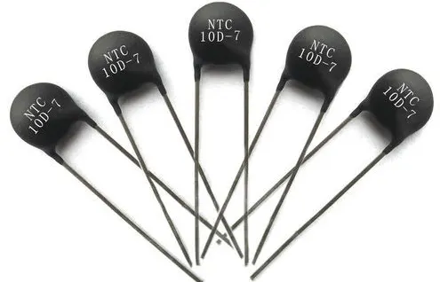
When the temperature of an NTC thermistor rises, the resistance lowers. In contrast, as the temperature drops, resistance rises. This is the most common type of thermistor. A PTC thermistor operates in a slightly different manner. As the temperature rises, the resistance rises, and when the temperature falls, the resistance falls. This thermistor is commonly used as a fuse. A thermistor typically achieves great precision within a narrow temperature range of roughly 50oC around the desired temperature. This range is affected by the base resistance.
Simulink model of a fan cantrol using thermister according the given conditions
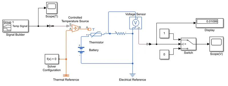
Blocks used in this model
1.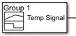 Signal Builder- This block allow you to create or generate interchangeable groups of piecewise linear signal sources which can be used as an input by a model. You can quickly switch the signal groups into and out of a model to facilitate testing. In signal builder window, create the signal and define the output waveform.
2. Simulink-PS Converter- This block converts the Simulink input signal to a Physical Signal. Before providing input to the circuit, the signal from the source is transformed into a physical signal.
3. PS-Simulink Converter- It converts the Physical signal to Simulink input signal. It is necessary to transform to Simulink signal before providing it to the display or scope as it only takes simulink singnal as input and conver it into display signal.
4.  Cantrolled Temperature Source- This block represents an ideal energy source in a thermal network that can maintain a controlled temperature difference regardless of the heat flow rate. The temperature difference is set by the physical signal port S. A positive temperature difference causes the temperature at port B to be greater than the temperature at port A.
5.  Thermal Reference- This block represents a reference point in a thermal network where the temperature is equal to absolute zero.
6. 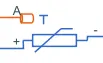 Thermister- This block represents an NTC thermistor using the B-parameter equation. The resistance at temperature T is given by R(T) = R0*exp(B*(1/T-1/T0)) where R0 is the Nominal resistance at the reference temperature T0, and B is the Characteristic temperature constant. The temperature T of the thermistor is governed by the equation m*c*dT/dt = Q where Q is the net heat flow into port A, m is the mass and c is the lumped specific heat capacity. The thermal mass m*c is calculated from the Thermal time constant t_c and the Dissipation factor K_d using the equation m*c = K_d*t_c.
7.  Resistor- The voltage-current (V-I) relationship for a linear resistor is V=I*R, where R is the constant resistance in ohms. The positive and negative terminals of the resistor are denoted by the + and - signs respectively. By convention, the voltage across the resistor is given by V(+)-V(-), and the sign of the current is positive when flowing through the device from the positive to the negative terminal. This convention ensures that the power absorbed by a resistor is always positive.
8.  Voltage Sensor- The block represents an ideal voltage sensor, that is, a device that converts voltage measured between any electrical connections into a physical signal proportional to the voltage. Connections + and - are conserving electrical ports through which the sensor is connected to the circuit. Connection V is a physical signal port that outputs voltage value.
9. Solver Configuration- It defines solver settings to use for simulation.
10. Battery- This block models a battery. If you select Infinite for the Battery charge capacity parameter, the block models the battery as a series internal resistance and a constant voltage source.
11. Electrical Reference- Electrical reference port. A model must contain at least one electrical reference port (electrical ground). A ground connection is essential in an electrical model.
12.  Constant- Output the constant specified by the 'Constant value' parameter. If 'Constant value' is a vector and 'Interpret vector parameters as 1-D' is on, treat the constant value as a 1-D array. Otherwise, output a matrix with the same dimensions as the constant value.
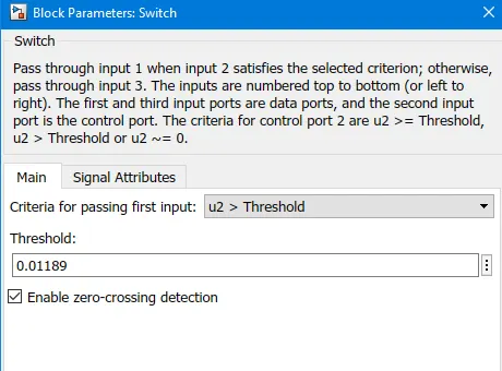
13.  Switch- Pass through input 1 when input 2 satisfies the selected criterion; otherwise, pass through input 3. The inputs are numbered top to bottom (or left to right). The first and third input ports are data ports, and the second input port is the control port. The criteria for control port 2 are u2 >= Threshold, u2 > Threshold or u2 ~= 0.
14.Scope- It shows the signal that is generated during simulation.
15. 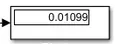 Display- Display input values. If the incoming signal is of type string, the 'Numeric display format' parameter selection does not affect the display of the string.
Note- First of all we have to convert the given value of temperature from celcius to kelvin in signal builder or repeating sequanece as thermistor only take kelvin temperature as an input.
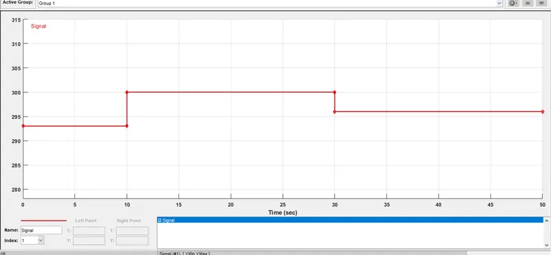 Temperture signal input using Signal Builder
Configuring the Switch
Here before provding the signal builder input, a constant value of 25 °C (298 K) is provided using a constant block. The constant value of temperature signal is converted in to electrical pulse by th mean of the the thermister and this value is recorded using a voltage sensor which is connected parallel to the circuit and the value of the voltage can be displayed on display block. This value is copied to the threshold in block parameters of the switch as shown below.
Construction and Working
Inputs are sent into the Signal Builder, which is then linked to a Temperature Controlled Source in order to maintain the required temperature differential across the source. The input temperature is then sent through the thermistor.
Thermistor is connected to resistor to ensure that the thermistor is connected to the positive terminal of the resistor and that the voltage across the resistor is given by V (+) -V (-) and that the sign of the current is positive when flowing through the device from the positive to the negative terminal. This rule assures that a resistor's absorbed power is always positive.Voltage sensor block is provided parallel to the resistor, to obtain the values from the Voltage sensor, connect the positive terminals of the Voltage sensor and the Resistor. Switch is attached to the voltage sensor's output terminal. Using the Switch Parameter, indicate that the fan must be turned on if the temperature exceeds 25oC and off otherwise. Output is successfully executed by connecting with scope in accordance with the specified criteria.
Result-The curve shows the changes in the voltage as the condition is mentioned.
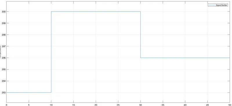
Signal from the signal builder
Signal from the voltage sensor
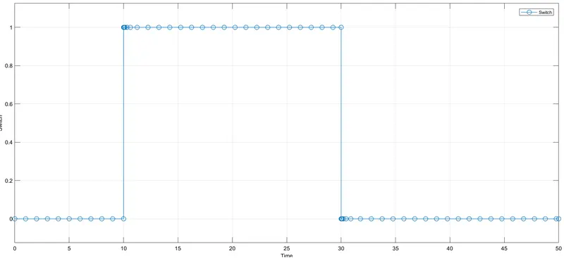
Conclusion- Here the time duration is takened 50 seconds, in that from 0-10 seconds the fan is in off condition due to temperature was 20°C (293K) which is below 25°C (298K). And during 10-30 seconds the temperature goes to 27°C (300K) which is greater than 298K, so according to given condition the fan must be in on condition. From 30-50 seconds due to temperature is 23°C(296K) which is below 25°C fan again goes to off condition.
Hence the given conditions are satisfied using signal builder and switch block.