Week 7 State of charge estimation
Aim-
1.Simulate the 3 test cases from harness dashboard and write a detailed report on the results.
2.What is coulomb counting? Refer to the above model and explain how BMS implements coulomb counting for SOC estimation ?
Before we have to simulate the 3 test cases from harness board we need to select the harness dashboard from the project file which can be downloaded from the link below:-https://in.mathworks.com/matlabcentral/fileexchange/72865-design-and-test-lithium-ion-battery-management-algorithms
The battery model harness dashboard is represented below.
1. Simulate the 3 test cases from harness dashboard and write a detailed report on the results.
Test 1.
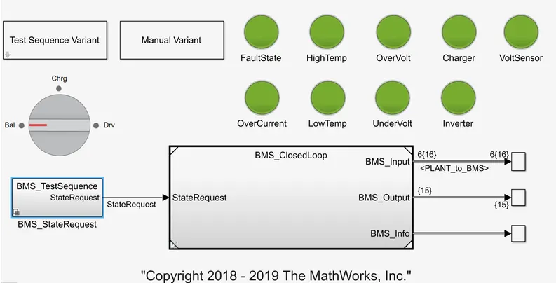
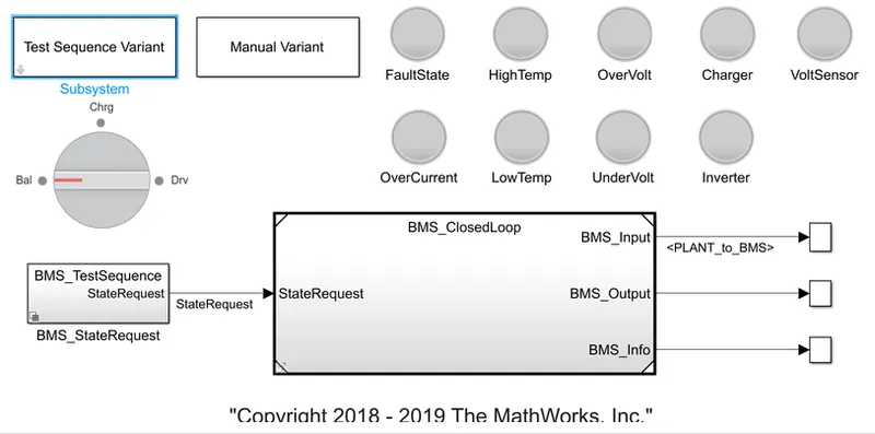
- Click on the Test Sequence Variant Block and select test case 1 and then click on the BMS state request block.
- By clicking on the BMS state reqyest block we will get the below chart
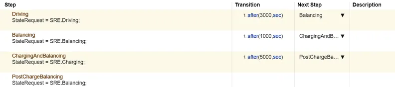
From the above figure we get to know that when the simulation will start, the model will be in driving condition where the driving is for 3000 seconds which is followed by 1000 seconds of balancing and the 5000 seconds of charging.
Here during the simulation we can see that the dashboard lighting or bulb is green as there are no fault detected in Test 1.
Results
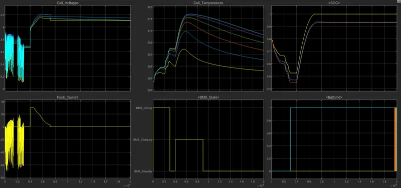
- Here the first plot shows the individual cell voltages. The voltage fluctuations is between 3.2V and 3.7V b/w till 3000 seconds. The nominal voltage of the cell is 3.7V which decreases to 3.2V as the vehicle is in driving mode. From 3000 to 4000 seconds, we have balancing mode, thus the voltage of the each cell get balanced to 4V till the end of 4000 seconds. From 4000 to 8000 seconds, the cells are in charging and balaancing state, hence the cell voltage is rises from 4V to 4.2V.
- The 2nd graph shows the plot for entire battery pack current vs time. Here we get to know that as the current decreases and went to negative thus the cell is charging and hence the current is -60A till 3000 seconds. Now from 3000 to 4000 seconds, the pack is in balancing mode hence here the balancing of cell took place and the pack current reduces to zero. From 4000 to 8000 seconds, there is charging and balancing state hence the current increases to 30A. Then occur post charge balancing, thus the current decreases back to zero.
- The third graph plots the temperture vs time of the whole pack. The cell temperature increases in driving stage as the cell pack is in use to run the motor. At balancing state the pack temperature reduces to some extend and again when the charging mode is on the temperature rapidly increases and then latter while the charging and post charging balancing is taking place the pack temperature reduces.
- The BMS state graph shows that the vehicle is in driving mode till 3000 seconds. From 3000 to 4000 seconds the vehicle is in study mode. From 4000 to 8000 seconds the battery is in charging state.
- The fifth graph shows the plot for state of charge of the battery pack. The SOC plot tells that, till 3000 seconds when the vehicle is in driving state, the SOC of the battery reduces from 80% to 45%. From 3000 to 4000 seconds as the vehicle is in study mode the pack SOC remains constant with 45%. During charging from 4000 to 8000 seconds the SOC increases to 100% and then remains constant.
- The cell balancing signal is shown in the balancedcommand graph.
Test 2.
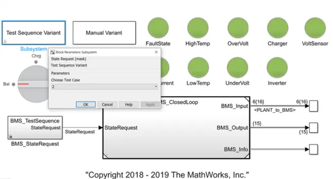
- Click on the Test Sequence Variant Block and select test case 2 and then click on the BMS state request block.
- By clicking on the BMS state reqyest block we will get the below chart

From the above figure we get to know that when the simulation will start, the model will be in driving condition where the driving is for 10000 seconds.
Results
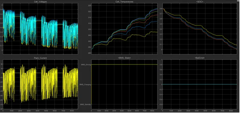
- Here the cell voltage fluctuates from 3.9V to 3.2V repeatedly as seen in graph of cell voltages.
- The battery pack current fluctuates from 0 to -60A and then rises to 10A repeatedly as shown.
- The cell temperature increases as there is driving stage from 0 to 10000 seconds.
- As driving stage is there from 0 to 10000 seconds, thus BMS graph shows the BMS driving.
- The SOC continue to reduce from 80% to 0%. The SOC do not increase because there is no charging and balancing stage. Though the driving stage is till 10000 seconds but as the battery discharges at 9000 seconds (as SOC is 0% at 9000 seconds) thus vehicle runs till 9000 seconds only.
Test 3.
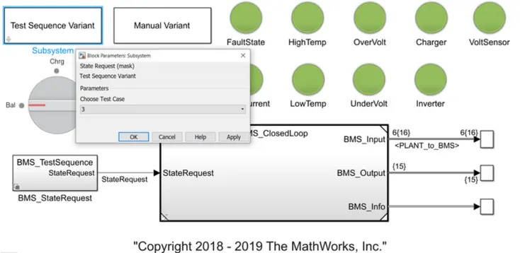
- Click on the Test Sequence Variant Block and select test case 3 and then click on the BMS state request block.
- By clicking on the BMS state reqyest block we will get the below chart.

From the above figure we get to know that when the simulation will start, the model will be in charging condition where the charging is for 20000 seconds.
Results
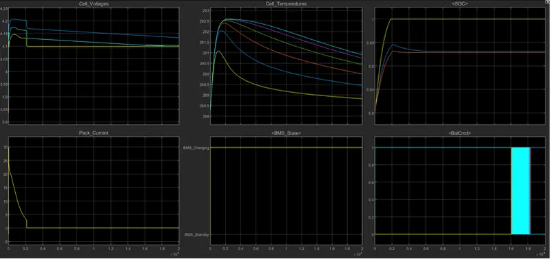
- The cell voltage varies till 20000 seconds and then remains constant.
- At start the pack current increases to 30A and then reduce to 0A at 2000 seconds and then remains constant at 0A.
- Cell temperature varies in the grapsh as shown.
- As there is only charging stage, the BMS graph shows BMS charging only.
- The SOC was 80% at first, then SOC increases to 100% in 2000 seconds which remains constant for the remaining time.
2. What is coulomb counting? Refer to the above model and explain how BMS implements coulomb counting for SOC estimation?
Coulomb counting- The coulomb counting is the method that measures the discharge current of the battery and integrates the discharging current over time in order to estimate the SOC. Coulomb counting method is done to estimate the SOC which is done by using the discharging current data, and previously estimated SOC values.
The SOC is calculated by the following equation:
`SOC(t) = SOC(t-1)+(I(t))/(Qn)*Deltat`
but there are several factors that affect the accuracy of the coulomb counting method including temperature, battery history, discharge current and cycle life.
Modified Coulomb Counting method- To improve the coulomb counting method, a new technique called modified coulomb counting method is proposed. The method uses the corrected current to improve the accuracy of the estimaation
The corrected current is the function of discharging current. There is a quadratic relationship between the corrected current and the discharging current of the battery pack. By practice of experimental data, corrected current is calculated by the following equation:
`underset(c)(I)(t)= underset(2)(k)*I(t)^2+underset(1)(k)*I(t)+underset(0)(k)`
here `underset(2)(k),underset(1)(k),underset(0)(k)` are constant values obtained from practice experimetal data.
In modified coulomb counting method, SOC is calculated by following equation:
`SOC(t) = SOC(t-1)+(underset(c)(I)(t))/(Qn)*Deltat`
The experimental results shows that the accuracy of the modiefied Coulomb counting method is superior to the conventional coulomb counting method.
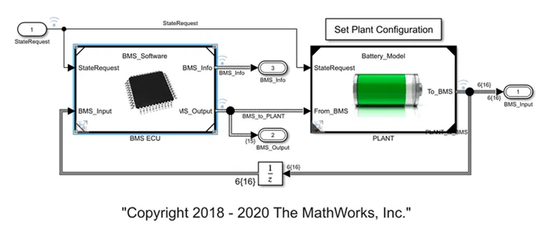
BMS algorithm models , protects , reports the measurement from battery pack.
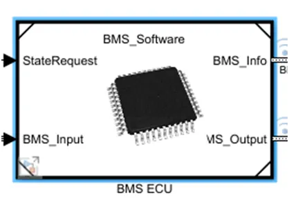
when we click on BMS ECU block we get,
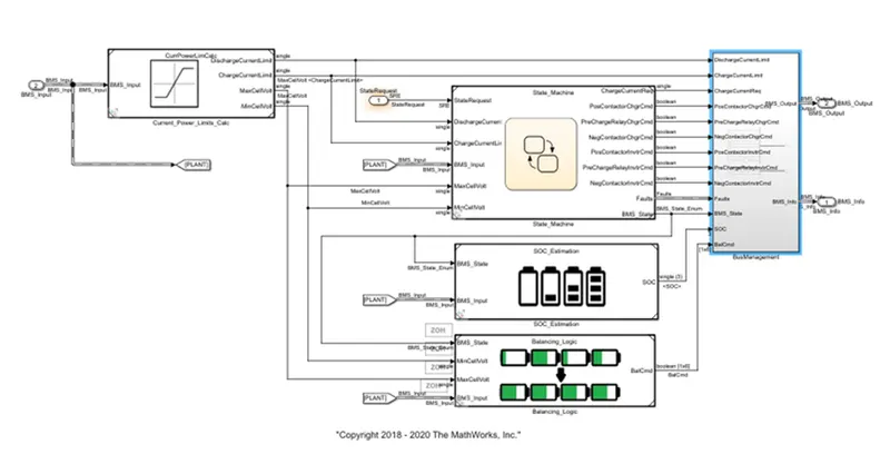
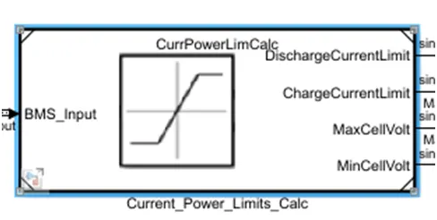
by clicking on the current power limit calc block , we get the below block diagram.
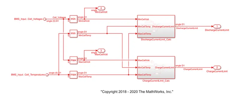
here the cell voltage and cell temperature is used to decide maximum allowable charging and discharging current limits.
when cell is at lowest SOC , its voltage is low,and thus it is important to prevent cell from delivering large amount of current because it wil cause large voltage drop that could be
potential below the cut off voltage specify by the cell manufacture.
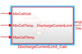
click on discharge current limit calculate block, we get the following block diagram shown below,
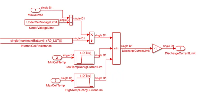
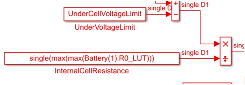
here by comparing the minimum cell voltage in the module against this lowest threshold voltage and then divided by maximum internal cell resistance value,
we can compute the voltage based threshold.
it is also important to limit the current delivery and current intake when temperature is too high or too low.
using the lockup table with rising and falling s shape profile, we can specify current threshold based temperature and thus can modulate allowable current delivery.
it is recommended to avoid low and high temperature during discharging and low temperature during charging.
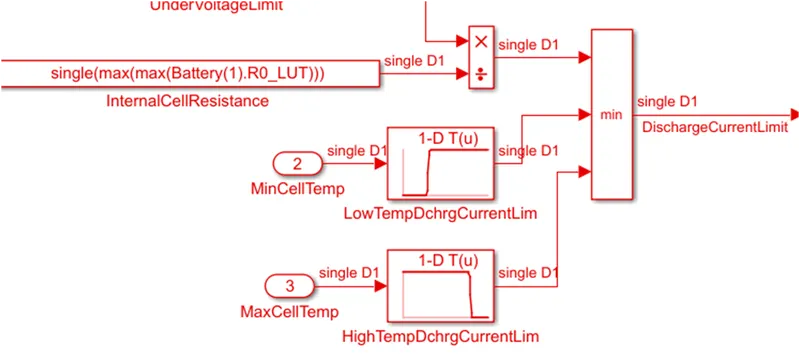
then the above two threshold are then compared and minimum of this two becomes the current limit.
knowing how much longer we can able to drive our car before we had to stop for recharge depends on the accurate estimation of battery SOC.
In battery system , we do not measure SOC directly , we actually measure something else and then relate it with SOC.
3 methods are used for SOC estimation.
but coulomb counting is mostly used.
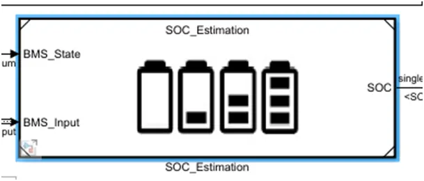
click on soc estimation block , we get,
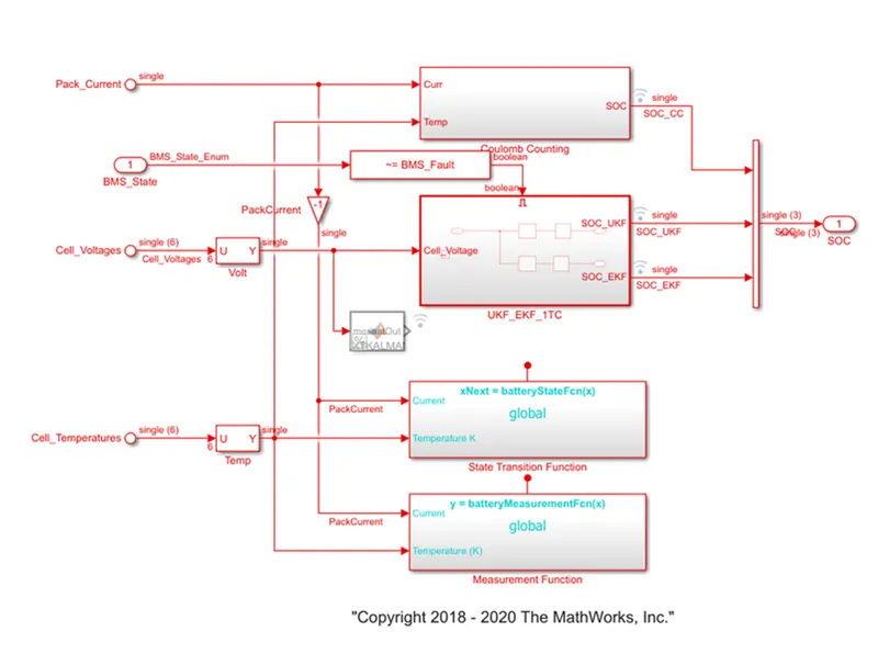
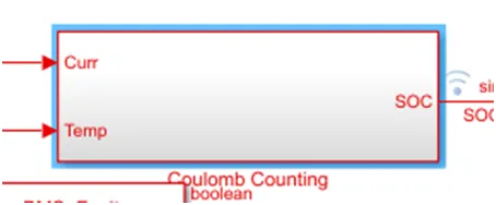
by clicking on coulomb counting block , we get the below block diagram
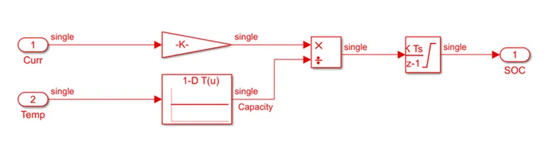
in this coulomb counting method, the entering and leaving currents of the cell are integrated to track the safe chargable time.
here the two input signals current and temperature are taken
the curent signal goes to gain block and the temperature signal goes to current look up table.
then as seen , signals are multiplied and divided as shown and then output is given to discrete time integrator to track the safe chargable time and then SOC is estimated.
advantage of coulomb counting method is its simplicity and low computational cost.
the drawback of coulomb counting method is accumulation of current sensor error and inability to recover from wrong initial condition because of lack of feedback from voltage
measurement.