Week-6 Challenge: EV Drivetrain
Week-6 Challenge: EV Drivetrain
Objectives
1. Which types of power converter circuits are employed in electric and hybrid electric vehicle?
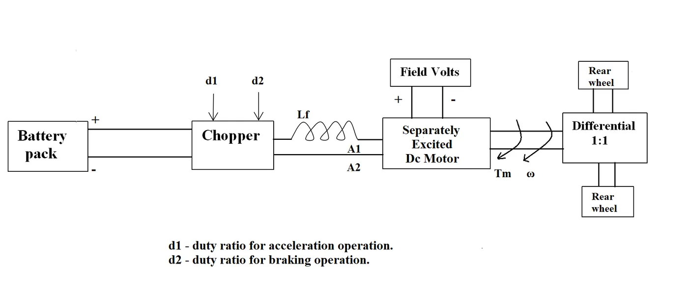
2. An Electric Vehicle's powertrain with 72V battery pack in shown in the diagram below. The duty ratio for acceleration operation is 'd1' and for the braking operation the duty ratio is 'd2'.
The other parameters of the electric vehicle is given below,
Motor and Controller Parameters:
Rated Armature voltage= 72 V
Rated armature current= 400 A
Ra= 0.5Ω, KΦ= 0.7 Volt second
Chopper Switching frequency= 400 Hz
The vehicle speed-torque characteristics are given by the below equation

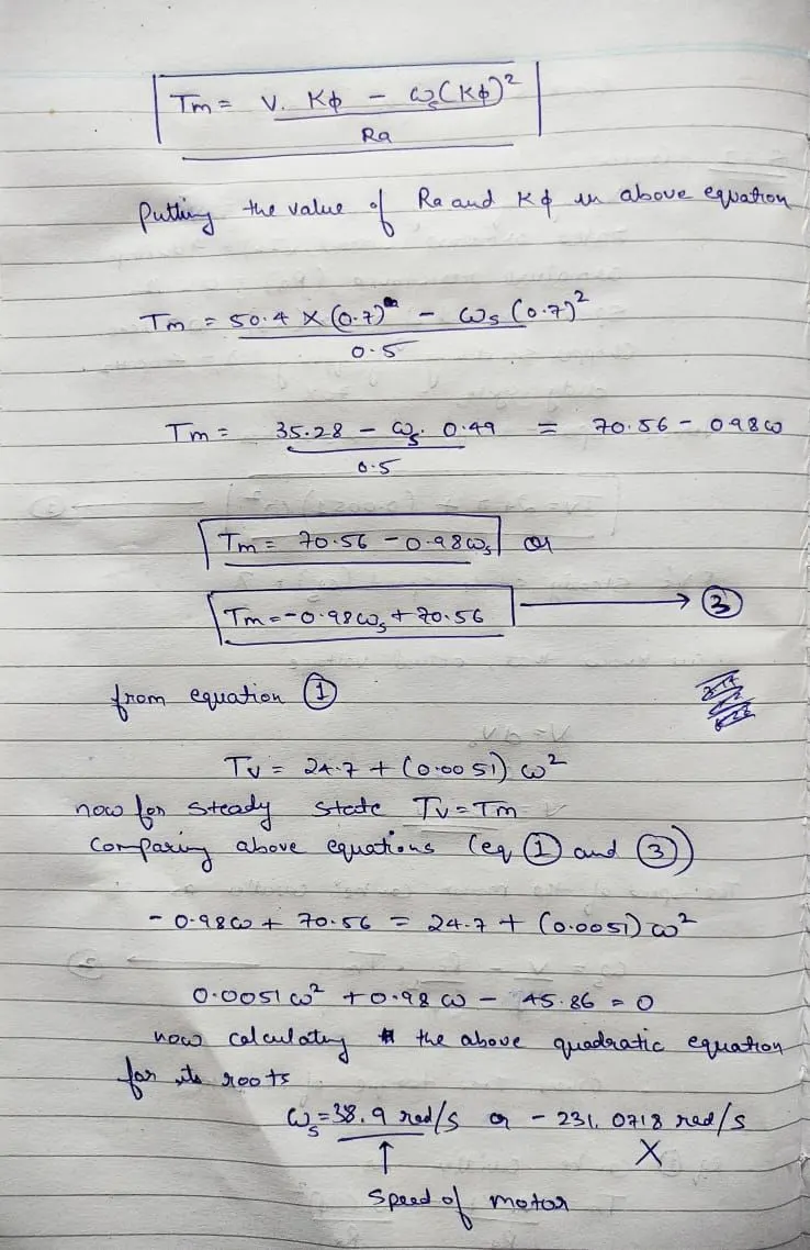
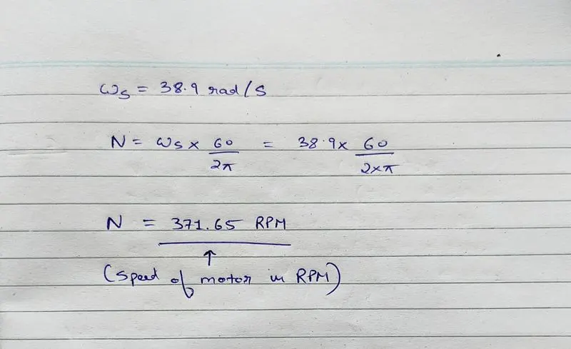
What is EV steady state speed if duty cycle is 70%?
3. Develop a mathematical model of a DC Motor for the below equation using Simulink.
ω">ωω= V/Kϕ">ϕϕ -Ra/Kϕ">ϕϕ^2 .T
4. Refer to the blog on below topic:
Induction Versus DC brushless motors by Wally Rippel, Tesla
Explain in brief about author’s perspective.
Objective 1. Which types of power converter circuits are employed in electric and hybrid electric vehicle?
Power electronics is one of the contemporary subjects of electrical engineering which has seen a lot of advancements in recent times and has impacted human life in almost every sphere. We over selves use so many power electronics applications in our daily life, without even realizing it.
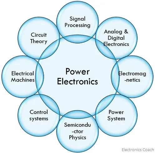
We can define power electronics as a subject which is a hybrid of power engineering, analogue electronics, semiconductor devices and control systems. We derive the fundamentals of each subject and apply it in an amalgamated way so as to get a regulated form of electrical energy. Electrical energy in itself is not usable until it is converted into a tangible form of energy such as motion, light, sound, heat etc. In order to regulate these forms of energy, an effective way is to regulate the electrical energy itself and this forms the content of the subject power electronics. The branch of electronics in which the application based on solid state electronics is studied for the control, manipulation and conversion of electrical power. The first high power electronic devices were mercury-arc valves. In modern systems, the conversion of the electrical power is basically performed by switching techniques which is done by semiconductor switching devices such as diodes, transistors, thyristors, MOSFET and IGBT.
Basically the electrical systems concerned with the transmission and processing of signals and data, in power electronics subtantial amount of electrical energy are processed. An AC/DC converter also called as rectifier is the most typical power electronic components which can be found in many consumer devices, e.g. personal computers, laptops, TVs, mobile phones, etc. The power ranges is typically from ten watts to several hundred watts. In industry a common applications is variable speed drive (or VSD) that is used to cantrol the induction motors. The power of VSD ranges from few hundred watts to tens of megawatt.
We can trace the overwhelming advancement in the subject back to the development of commercial thyristors or silicon controlled rectifiers (SCR) by General Electric Co. in 1958. Before this the control of electrical energy was mainly done using thyratrons and mercury arc rectifiers which works on the principle of physical phenomena in gases and vapours.
After SCR, a great many power electronic devices have emerged like GTO, IGBT, SIT, MCT, TRIAC, DIAC, IEGT, IGCT and so on. These devices are rated for several hundreds of volt and ampere unlike the signal level devices which work at few volts and mill amperes.
In order to achieve the purpose of power electronics, the devices are made to work as nothing more than a switch. All the power electronic devices act as a switch and have two modes, i.e. ON and OFF.
For example, a BJT (Bipolar Junction Transistor) has three regions of operation in its output characteristics cut-off, active and saturation. In analogue electronics where the BJT is supposed to work as an amplifier, the circuit is so designed to bias it in active region of operation. However in power electronics BJT will work in cutoff region when it is OFF and in saturation region when it is ON.
Now that the devices are required to work as a switch, they must follow the basic characteristic of a switch, i.e. when the switch is ON, it has zero voltage drop across it and carries full current through it, and when it is in OFF condition, it has full voltage drop across it and zero current flowing through it. The figure below depicts the above statement-
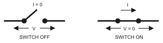
Now since in both the mode either of the quantity V or I is zero, the switch power also turns out to be zero always. This characteristic is easy to visualize in a mechanical switch and the same has to be followed in power electronic switch also.
However practically there always exists a leakage current through the devices when in OFF condition, i.e Ileakage ≠ 0 and there is always a forward voltage drop in ON condition, i.e Von ≠ 0. However the magnitude of Von or Ileakage is very less and hence the power across the device is also very less, in order of few millwatts.
This power is dissipated in the device and hence proper heat evacuation from the device is an important aspect. Apart from this ON state and OFF state losses, there are switching losses also in power electronic devices. This is mainly while the switch toggles from one mode to another and V and I across the device changes. In power electronics both the losses are important parameters of any device and essential in determining its voltage and current ratings.
The power electronic devices alone are not that useful in practical applications and hence require to be designed with a circuit along with other supporting components. These supporting components are like the decision making part which controls the power electronic switches in order to achieve the desired output. This includes the firing circuit and the feedback circuit. The block diagram below depicts a simple power electronic system.
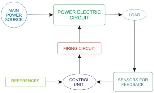
The Control Unit takes the output feedback from sensors and compares it with references and accordingly gives input to the firing circuit. Firing circuit is basically a pulse generating circuit which gives pulse output in a fashion so as to control the power electronic switches in the main circuit block.
The net result is that the load receives the desired electrical power and hence delivers the desired result. A typical example of the above system would be speed control of motors. Majorly there are five types of power electronic circuits, each having different purpose-
- Rectifiers – converts fixed AC to variable DC (such as half wave rectifiers or full wave rectifiers)
- Choppers – converts fixed DC to variable DC
- Inverters – converts DC to AC having variable amplitude and variable frequency
- Voltage Regulators – converts fixed AC to variable AC at same input frequency
- Cycloconverters – converts fixed AC to AC with variable frequency
There is a common misconception about the term converter. Converter is basically any circuit that converts electrical power from one form to another.
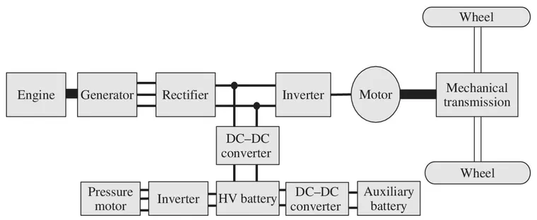
Power electronics plays a major role in the design and manufacturing of convetional IC engine vehicles, EVs and HEVs. In electric and hybrid electric vehicles, power electronic converters are considered as the key element that interfece between the power sources to the drivetrain. In order to design highly efficient power converter for the EV's power system, advanced DC/DC, DC/AC, AC/DC and AC/AC converters are required to adapt the output voltage and current levels with high power quality.
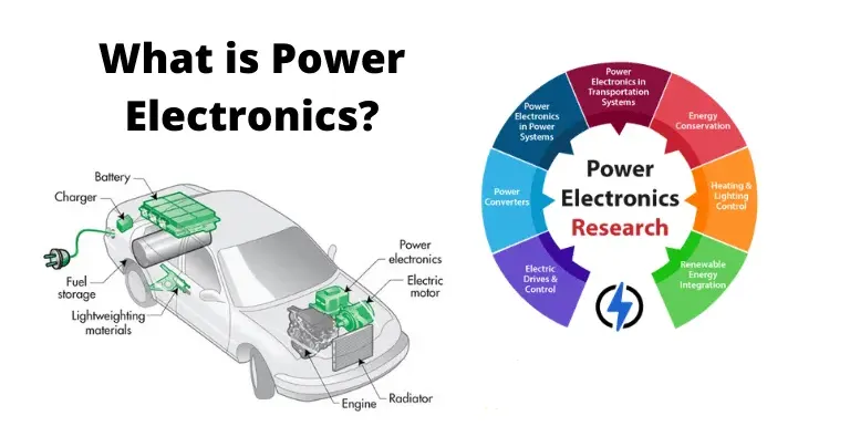
There are different types of power converter which constitutes in powertrain of EVs and HEVs, :
1. AC-DC Converter (Rectifier)
In a large number of electrical and electronic circuits, DC voltage is required for its operation. We can simply alter the AC voltage into DC voltage by using a device called a PN junction diode. One of the most significant applications of a PN junction diode is the rectification of AC into DC. A PN junction diode permits electric current in only one direction i.e, forward bias condition, and blocks electric current in reverse bias condition. This single property of the diode lets it perform like a rectifier. This article discusses different types of rectifiers, working, and their comparisons.
A rectifier is an electrical device comprised of one or more diodes that allow the flow of current only in one direction. It basically converts alternating current into direct current. Rectifiers can be mold in several shapes as per necessity like semiconductor diodes, SCRs (silicon controlled rectifiers), vacuum tube diodes, mercury-arc valves, etc. In our previous articles, we have explained diodes, types of diodes in detail. But in this, we are going to give details of rectifiers, types of rectifiers and their applications, etc. For signal discovery and power rectification, diode rectifier circuits are extensively used in designing electronic circuits, which are used in various devices like radio signals or detectors, DC power supplies, household appliances like video game systems, laptops, televisions, etc.

2. DC-AC Converter (Inverter)
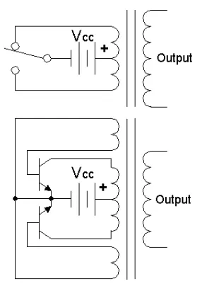
A power inverter is a power electronic device that converts the direct current to an alternating current. The resulting AC frequency obtained depends on the particular device employed. Inverters do the opposite of rectifiers which originally large electromechanical devices converting AC to DC.The input voltage, output voltage and frequency and overall power handling depends on the design of the specific device or circuitary. The inverter does not produce any power, and power is provided by DC source.
A power inverter can be entirely electronic or may be a combination of mechanical effects (such as a rotary apparatus) and electronic circuitry. Static inverters do not use moving parts in the conversion process.Power inverters are primarily used in electrical power applications where high currents and voltages are present; circuits that perform the same function for electronic signals, which usually have very low currents and voltages, are called oscillators.
3. AC-AC Converter (Regulator)
A voltage regulator is a circuit that creates and maintains a fixed output voltage, irrespective of changes to the input voltage or load conditions. Voltage regulators (VRs) keep the voltages from a power supply within a range that is compatible with the other electrical components. While voltage regulators are most commonly used for DC/DC power conversion, some can perform AC/AC or AC/DC power conversion as well. This article will focus on DC/DC voltage regulators. There are many different types of voltage regulator.
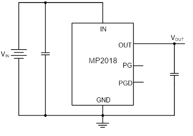
- Linear Regulator- A linear voltage regulator utilizes an active pass device (such as a BJT or MOSFET), which is controlled by a high-gain operational amplifier. To maintain a constant output voltage, the linear regulator adjusts the pass device resistance by comparing the internal voltage reference to the sampled output voltage, and then driving the error to zero. Linear regulators are step-down converters, so by definition the output voltage is always below the input voltage. However, these regulators offer a few advantages: they are generally easy to design, dependable, cost-efficient, and offer low noise as well as a low output voltage ripple. Linear regulators, such as the MP2018, only require an input and output capacitor to operate. Their simplicity and reliability make them intuitive and simple devices for engineers, and are often highly cost-effective.
-
Switching Regulator- A switching regulator circuit is generally more complicated to design than a linear regulator, and requires selecting external component values, tuning control loops for stability, and careful layout design. Switching regulators can be step-down converters, step-up converters, or a combination of the two, which makes them more versatile than a linear regulator. Advantages of switching regulators include that they are highly efficient, have better thermal performance, and can support higher current and wider VIN / VOUT applications. They can achieve greater than 95% efficiency depending on the application requirements. Unlike linear regulators, a switching power supply system may require additional external components, such as inductors, capacitors, FETs, or feedback resistors. The HF920 is an example of a switching regulator that offers high reliability and efficient power regulation
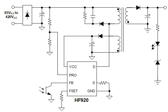
There are various topologies for linear and switching regulators. Linear regulators often rely on low-dropout (LDO) topologies. For switching regulators, there are three common topologies: step-down converters, step-up converters, and buck-boost converters. Each topology is described below:
LDO Regulators- One popular topology for linear regulators is a low-dropout (LDO) regulator. Linear regulators typically require the input voltage to be at least 2V above the output voltage. However, an LDO regulator is designed to operate with a very small voltage difference between input and output terminals, sometimes as low as 100mV.
Step Down & Step up regulator- Step-down converters (also called buck converters) take a larger input voltage and produce a lower output voltage. Conversely, step-up converters (also called boost converters) take a lower input voltage and produce a higher output voltage.
Buck Boost Converters- A buck-boost converter is a single-stage converter that combines the functions of a buck and a boost converter to regulate the output over a wide range of input voltages that can be greater or less than the output voltage.
3. DC-DC Converter (Chopper)
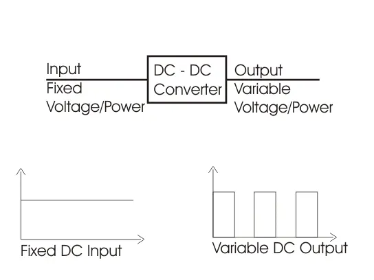
DC to DC converter is very much needed nowadays as many industrial applications are dependent upon DC voltage source. The performance of these applications will be improved if we use a variable DC supply. It will help to improve controllability of the equipments also. Examples of such applications are subway cars, trolley buses, battery operated vehicles etc. We can control and vary a constant DC voltage with the help of a chopper. Chopper is a basically static power electronics device which converts fixed DC voltage/power to variable DC voltage or power. It is nothing but a high speed switch which connects and disconnects the load from source at a high rate to get variable or chopped voltage at the output.
 _______________________________________________________________________________________________________
Objective 2. An Electric Vehicle's powertrain with 72V battery pack in shown in the diagram below. The duty ratio for acceleration operation is 'd1' and for the braking operation the duty ratio is 'd2'.
The other parameters of the electric vehicle is given below,
Motor and Controller Parameters:
Rated Armature voltage= 72 V
Rated armature current= 400 A
Ra= 0.5Ω, KΦ= 0.7 Volt second
Chopper Switching frequency= 400 Hz
The vehicle speed-torque characteristics are given by the below equation
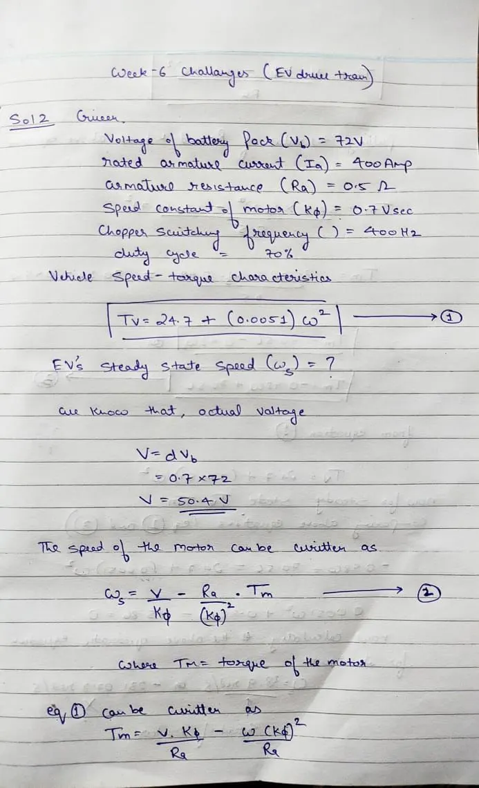
What is EV steady state speed if duty cycle is 70%?
Solution.
_______________________________________________________________________________________________________
Objective 3. Develop a mathematical model of a DC Motor for the below equation using Simulink.
ω">ωω= V/Kϕ">ϕϕ -Ra/Kϕ">ϕϕ^2.T
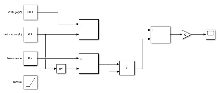
Blocks used
- 3 Constant block (for Voltage, motor constant and resistance)
- 1 Ramp block (for torque)
- 3 divide block
- 1 square block
- 1 product block
- 1 Gain block
- 1 Scope block
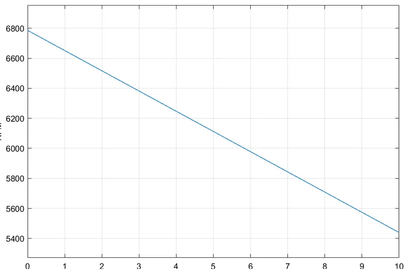
Output
_______________________________________________________________________________________________________
Objective 4. Refer to the blog on below topic:
Induction Versus DC brushless motors by Wally Rippel, Tesla
Explain in brief about author’s perspective.
Wally Rippel is a long-time proponent of electric vehicles. Prior to joining Tesla Motors, he was an engineer at AeroVironment, where he helped develop the EV1 for General Motors and was featured in the documentary movie, Who Killed the Electric Car? Wally has also worked for the Jet Propulsion Laboratory on electric vehicle battery research, among other projects. In 1968, as a Caltech undergraduate student, he built an electric car (a converted 1958 Volkswagen microbus) and won the Great Transcontinental Electric Car Race against MIT.
Wally Ripple firstly gave the description of DC brushless motor about its parts and specifications and what is called and next description about induction motor and its components and working of induction motor. Then he compared the DC brushless motor and AC induction motor, which is mentioned that #- phase AC induction motor can produce output torque and also have an ability to start under the load without any inverter, as of DC brushless motor produces no starting torque when directly connected to fixed frequency utility power and also inverter is needed to start under load. Then he also discussed about the limitations of the 3- phase induction motor they cannot operate from DC, hence AC is must. Shaft speed is appropriate to line frequency. Hence, when used with utility power, they are constant speed machines. Finally when operated from utility power, they have limited starting torque and somewhat limited running peak torque capabilities, when compared to DC type machines. Inverter can be added to 3-phase induction so that we can supply power from DC source or battery and also we can get variable speed and can adjust the frequency.
He also discussed as the only main difference between DC brushless and induction motor is of cantrol code and also the rotor of the DC brushless get less heated at peak toque as compared to the 3-phase induction motor.
After that he also told about the loses when the motor runs which is the induction machine when operated with the smart inverter has an advantage over DC brushless machine- magnetic and conduction loses can be traded such that the efficiency is optimised. This advavtage becomes increasingly important as a performance is increased. With DC brushhless motor, as machine size grows, magnetic loses increases proportionally and part load efficiency drops. With induction, as machine size grows, loses size donot necessarily grows. Thus, induction drives maybe the favoured approach where high- performance is desired; peak efficiency will be little less that that of DC brushless, but average efficiency may actually be better.
He then concluded that DC brushless drives will likely continue to dominate the hybrid and coming plug-in hybrid market, and induction drives will likely maintain dominance for high performance pure electrics.