Project-1: Powertrain for aircraft in runways
Aim- Powertrain for aircraft in runways
Main Objectives-
Part A:
1. Search and list out the total weight of various types of aircrafts.
2. Is there any difference between ground speed and air speed?
3. Why is it not recommended to use aircraft engine power to move it on the ground at Airport?
4. How an aircraft is pushed to runway when its ready to take off?
5. Learn about take off power, tyre design, rolling resistance, tyre pressure, brake forces when landing.
Part B:
6. A. With necessary assumptions, calculate the force and power required to push / pull an aircraft by a towing vehicle.
B. Develop the model for the calculated force and power using Simulink.
7. A. Design an electric powertrain with type of motor, it’s power rating, and energy requirement to fulfill aircraft towing application in Simulink. Estimate the duty cycle range to control the aircraft speed from zero to highest. Make all required assumptions. Prepare a table of assumed parameters. Draw a block diagram of powertrain.
(Hint :DC7 Block)
B. Also, Design the parameters in excel sheet.
Part A:
1. Search and list out the total weight of various types of aircrafts.
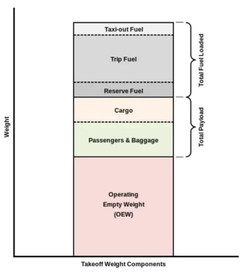
The list of various types of aircraft is listed in below word document link and is arranged in increasing order of the maximum take of weight.
2. Is there any difference between ground speed and air speed?
Ground speed- Ground speed is the horizontal speed of an aircraft relative to the Earth's surface. It is vital for accurate navigation to the destination that the pilot has an estimate of the ground speed that will be achieved during a flight. An aircraft diving vertically would have a ground speed of zero. For a reference point picked on the ground, the aircraft moves relative to the reference point at the ground speed. Ground speed is also a vector quantity. So, a comparison of the ground speed to the wind speed must be done according to rules for vector comparisons.
Airspeed- Airspeed is the vector difference between the ground speed and the wind speed. On a perfectly still day, the airspeed is equal to the ground speed. But if the wind is blowing in the same direction that the aircraft is moving, the airspeed will be less than the ground speed. The important quantity in the generation of lift is the relative velocity between the object and the air, which is called the airspeed. Airspeed cannot be directly measured from a ground position, but must be computed from the ground speed and the wind speed. Airspeed is the vector difference between the ground speed and the wind speed.
Wind Speed- Wind speedFor a reference point picked on the ground, the air moves relative to the reference point at the wind speed. Notice that the wind speed is a vector quantity and has both a magnitude and a direction. Direction is important. A 20 mph wind from the west is different from a 20 mph wind from the east. The wind has components in all three primary directions (north-south, east-west, and up-down). In this figure, we are considering only velocities along the aircraft's flight path. A positive velocity is defined to be in the direction of the aircraft's motion. We are neglecting cross winds, which occur perpendicular to the flight path but parallel to the ground, and updrafts and downdrafts, which occur perpendicular to the ground.
Airspeed = Ground Speed - Wind Speed
On a perfectly still day, the airspeed is equal to the ground speed. But if the wind is blowing in the same direction that the aircraft is moving, the airspeed will be less than the ground speed.
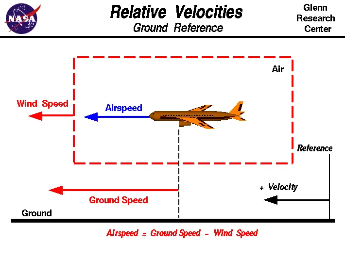
The relation between the ground speed and air speed depends on the direction of the aircraft and the wind. If the wind and the aircraft is moving in the same direction then the speed of aircraft and the velocity of the wind is added together for airspeed whereas, if the wind and aircraft is moving in the opposite direction then the airspeed will be the less than the initial one.
From the above image 2 case can be considered:-
Case1- In first case the velocity of wind is taken as 40 kmph and the speed of aircraft is 160kmph and both the wind and aircraft is moving in the same direction then the relative speed between the wind and aircraft is 200kmph. The relative speed between wind and aircraft is called as groundspeed.
Case2- In second case the velocity of the wind is taken as 40kmph and the aircraft is 160kmph and the motion of aircraft and wind are opposite to each other hence the value of the wind speed in this case is taken negative then the relative speed between the wind and aircaft becomes 140kmph.
3. Why is it not recommended to use aircraft engine power to move it on the ground at Airport?
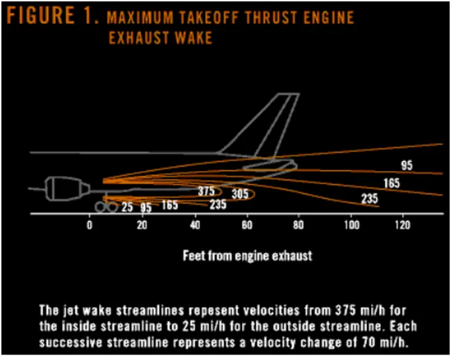
When modern jet engines are operated at rated thrust levels, the exhaust wake can exceed 375 mi/h (325 kn or 603 km/h) immediately aft of the engine exhaust nozzle. This exhaust flow field extends aft in a rapidly expanding cone, with portions of the flow field contacting and extending aft along the pavement surface (fig. 1). Exhaust velocity components are attenuated with increasing distance from the engine exhaust nozzle. However, an airflow of 300 mi/h (260 kn or 483 km/h) can still be present at the empennage, and significant people and equipment hazards will persist hundreds of feet beyond this area. At full power, the exhaust wake speed can typically be 150 mi/h (130 kn or 240 km/h) at 200 ft (61 m) beyond the airplane and 50 to 100 mi/h (43 to 88 kn or 80 to 161 km/h) well beyond this point.
The risks which may arise from engine ground running relate to the potential for loss of control of the aircraft by those persons occupying the pilot seats in the flight deck. Unwanted consequences from such static running are mainly related to those arising from the unintended movement of the aircraft during engine running - effectively a loss of control - especially during high power engine running. Damage can occur to the aircraft itself, other aircraft nearby or to airside structures. In addition, there is a risk of injury to ground support personnel who may be in relatively close proximity to the aircraft as it me suck the nearby personel into its powerful engine.
The extensive noise arises from the engine power also dangerous for humans and other living things around the vicinity.
Hence for the above reasons it is not recommended to use engine power to move on the ground.
4. How an aircraft is pushed to runway when its ready to take off?
In aviation, pushback is an airport procedure during which an aircraftis pushed backwards away from an airport gate by external power. Pushbacks are carried out by special, low-profile vehicles called pushback tractors or tugs.
Although many aircraft are capable of moving themselves backwards on the ground using reverese thrust (a procedure referred to as a powerback), the resulting jetblast or propwash might cause damage to the terminal building or equipment. Engines close to the ground may also blow sand and debris forward and then suck them into the engine, causing damage to the engine. A pushback is therefore the preferred method to move the aircraft away from the gate.
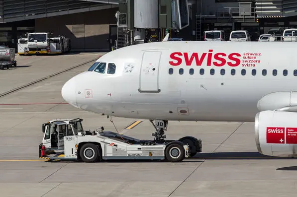
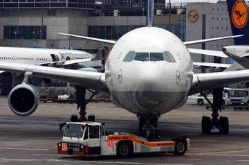

The above fig shows a conventional tractor hucked up to the aircraft which is used to tow the aircraft from the taxiway and the last figure is to connect the tractor to the aircraft.
Pushbacks at busy aerodromes are usually subject to ground control clearance to facilitate ground movement on taxiways. Once clearance is obtained, the pilot will communicate with the tractor driver (or a ground handler walking alongside the aircraft in some cases) to start the pushback. To communicate, a headset may be connected near the nose gear.
Since the pilots cannot see what is behind the aircraft, steering is done by the pushback tractor driver and not by the pilots. Depending on the aircraft type and airline procedure, a bypass pin may be temporarily installed into the nose gear to disconnect it from the aircraft's normal steering mechanism.
Once the pushback is completed, the towbar is disconnected, and any bypass pin removed. The ground handler will show the bypass pin to the pilots to make it clear that it has been removed. The pushback is then complete, and the aircraft can taxi forward under its own power.
5. Learn about take off power, tyre design, rolling resistance, tyre pressure, brake forces when landing.
Take-Off Power:- For light aircraft, usually full power is used during takeoff. Large transport category (airliner) aircraft may use a reduced power for takeoff, where less than full power is applied in order to prolong engine life, reduce maintenance costs and reduce noise emissions. In some emergency cases, the power used can then be increased to increase the aircraft's performance. Before takeoff, the engines, particularly piston engines, are routinely run up at high power to check for engine-related problems. The aircraft is permitted to accelerate to rotation speed (often referred to as Vr). The term rotation is used because the aircraft pivots around the axis of its main landing gear while still on the ground, usually because of gentle manipulation of the flight controls to make or facilitate this change in aircraft attitude (once proper air displacement occurs under / over the wings, an aircraft will lift off on its own; controls are to ease that in).
The nose is raised to a nominal 5°–15° nose up pitch attitude to increase lift from the wings and effect liftoff. For most aircraft, attempting a takeoff without a pitch-up would require cruise speeds while still on the runway.
Tyre Design:- Designing aircraft tires is a very intense undertaking. Once an aircraft manufacturer goes to the tire manufacturer with the size and weight requirements, the tire manufacturer begins the process of designing a tire that meets the needs of the aircraft manufacturer as well as all regulatory requirements — including foreign regulations in many cases.
Engineers are challenged with designing tires with cool running, heat-resistant materials while simultaneously exceeding tire service requirements. Tire prototypes are put through rigorous tests that simulate cycles of landings, take-offs, and taxi operations. It is only after the tires pass all mandatory tests and meet the requirements of the aircraft manufacturer and airworthiness authorities that the tires are put into production.
Two types of tires are used in aircraft applications — bias-ply tires and radial tires. Although both types of tires share some similarities in design, there are differences that need to be noted.
-> Based on the type of plies used the tyres can be:
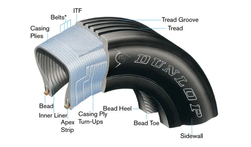
Radial ply tires - these tyres feature a flexible casing which is constructed of rubber-coated ply cords which extend around the beads and are substantially at 90° to the centerline of the tread. The casing is stabilized by an essentially inextensible circumferential belt.
A typical radial tire is illustrated in the above Figure. With their rigid belt, they provide increased landings and reduced rolling resistance. They have fewer components in their construction and are lighter than similarly sized bias ply tires. Components that differ from bias-ply construction as follows:
Overlay: A layer of reinforcing rubber coated fabric placed on top of the belts to aid in high speed operation.
Belt Plies: A composite structure that stiffens the tread area for increased landings. The belt plies increase the tire strength in the tread area.
Casing Plies: As in bias-ply tires, the casing plies are layers of rubber-coated fabric. However, unlike those in bias plies that run at opposite angles to one another, radial plies run radially from bead to bead.
Chippers: The chippers are layers of rubber-coated fabric applied at diagonal angles that improve the durability of the tire in the bead area.
Bias ply tires - these tyres feature a casing which is constructed of alternate layers of rubber-coated ply cords which extend around the beads and are at alternate angles substantially less than 90° to the center line of the tread.
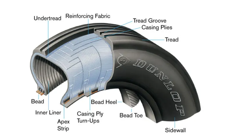
A cutaway of a typical bias-ply tire is shown in Figure. Bias-ply tires are popular choices for aircraft tires because of their durability and retreadability. The tire construction consists of the following components:
Tread: The tread is made of rubber mixed with other additives to obtain the desired level of toughness, durability, and resistance to wear. The tread pattern is designed to aircraft operational requirements, with the ribbed tread design used widely due to its good traction under varying runway conditions.
Sidewall: The sidewall is a protective layer of rubber that covers the outer casing ply. It extends from the tread edge to the bead area.
Tread Reinforcing Ply: One or more layers of fabric that strengthens and stabilizes the tread area for high-speed operation. It also serves as a reference for the buffing process when tires are retreaded.
Buff Line Cushion: The buff line cushion is made of rubber compound to enhance the adhesion between the tread reinforcing ply and the breakers or casing plies. It is of sufficient thickness to allow for the removal of the old tread when the tire is retreaded.
Breakers: Breakers are reinforcing plies of rubber-coated fabric placed under the buff line cushion to protect casing plies and strengthen and stabilize the tread area. They are considered an integral part of the casing construction.
Casing Plies: Alternate layers of rubber-coated fabric (running at opposite angles to one another) provide the strength of the tire.
Wire Beads: Hoops of high tensile strength steel wire that anchor the casing plies and provide a firm mounting surface on the wheel. The outer edge of the bead that fits against the wheel flange is called the bead heel. The inner bead edge is called the bead toe.
Apex Strip: A wedge of rubber affixed to the top of the bead bundle.
Flippers: Layers of rubberized fabric that help anchor the bead wires to the casing and improve the durability of the tire.
Ply Turnups: The casing plies are anchored by wrapping them around the wire beads, thus forming the ply turnups.
Chafer: A protective layer of rubber and/or fabric located between the casing plies and wheel to minimize chafing.
Liner: In tubeless tires, the liner is a layer of low permeability rubber that acts as a built-in tube and restricts gas from diffusing into the casing plies. In tube-type tires, a thinner liner is used to prevent tube chafing against the inside ply.
->Based on the method for containing the inflation gas the tyres can be:
- Tube-type tyres - these require tubes for inflation retention.
- Tubeless tyres - these do not require tubes. They are constructed with an innerliner (integral rubber lining that is engineered to prevent the diffusion of the inflation gas into the casing.).
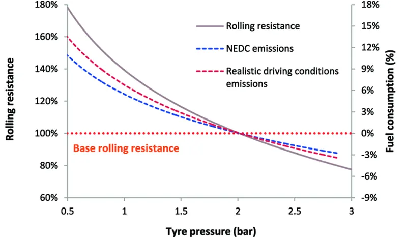
Rolling Resistance:- The resistance offered by the tyres against motion of vehicle/aircraft is called as rolling resistance, the rolling resistance is produced during take off/landing in the runway.
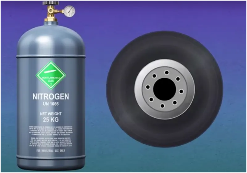
Tyre Pressure:- Aircraft tires are usually inflated with nitrogen to minimize expansion and contraction from extreme changes in ambient temperature and pressure experienced during flight. Dry nitrogen expands at the same rate as other dry atmospheric gases (normal air is about 80% nitrogen), but common compressed air sources may contain moisture, which increases the expansion rate with temperature.
Tests of airliner aircraft tires have shown that they are able to sustain pressures of maximum 800 psi (55 bar; 5,500 kPa) before bursting. During the tests the tires have to be filled with water, to prevent the test room being blown apart by the energy that would be released by a gas when the tire bursts.
The main landing gear on the Concorde was typically inflated to 232 psi (16.0 bar), whilst its tail bumper gear tires were as high as 294 psi (20.3 bar). The high pressure and weight load on the Concorde tyres were a significant factor in the loss of Air France flight 4590
Tests of airliner aircraft tires have shown that they are able to sustain pressures of maximum 800 psi (55 bar; 5,500 kPa) before bursting. During the tests the tires have to be filled with water, to prevent the test room being blown apart by the energy that would be released by a gas when the tire bursts. Aircraft tires are usually inflated with nitrogen to minimize expansion and contraction from extreme changes in ambient temperature and pressure experienced during flight. Dry nitrogen expands at the same rate as other dry atmospheric gases (normal air is about 80% nitrogen), but common compressed air sources may contain moisture, which increases the expansion rate with temperature. The requirement that an inert gas, such as nitrogen, be used instead of air for inflation of tires on certain transport category airplanes was prompted by at least three cases in which the oxygen in air-filled tires had combined with volatile gases given off by a severely overheated tire and exploded upon reaching autoignition temperature. The use of an inert gas for tire inflation eliminates the possibility of tire explosion.
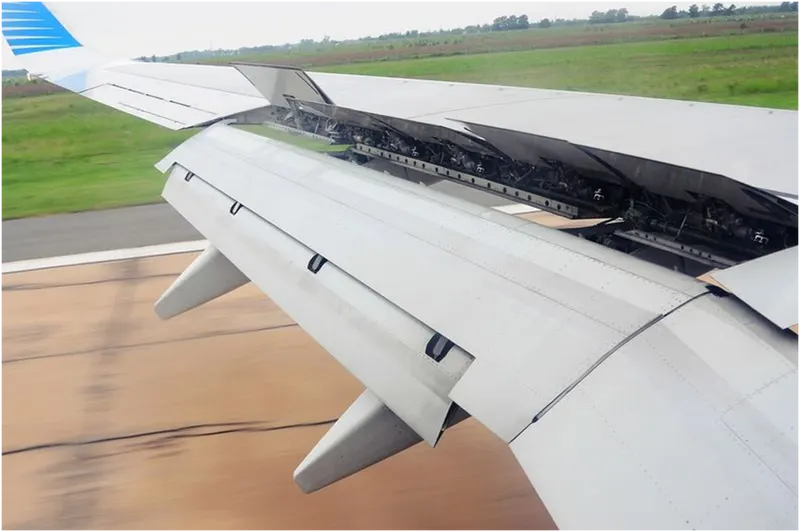
Brakes Forces When Landing:- In general, when the wheels touch the ground, a set of spoilers raise up quickly, which kills the lift provided by the wings. (There are two sets seen in the image below: ground spoilers that only deploy on landing, and spoilers that are used in flight as speed brakes as well as on landing.) While the spoilers provide some drag, their primary purpose is to stop the plane from actually flying, putting all of the weight on the landing gear and in turn making the brakes that much more effective.
An aircraft lands at a speed close to 250 Kmph. Hence it becomes necessary to resist its speed within a minimum stipulation of time to bring the aircraft to the rest position. The braking devices which are used to deaccelerate the aircraft are:
1.) Wheel brakes (Including Anti Skid systems and Anti brake systems)
2.) Spoilers
3.) Reverse Thrust
Wheel Brakes: Aircraft brakes stop a moving aircraft by converting its kinetic energy to heat energy by means of friction between rotating and stationary discs located in brake assemblies in the wheels. Brakes provide this critical stopping function during landings to enable airplanes to stop within the length of the runway. They also stop aircraft during rejected takeoff events, in which an attempted takeoff is canceled as the airplane is rolling down the runway before it lifts off from the ground due to engine failure, tire blowout, other system failure or direction from air traffic control.
The most common type of brake used on aircraft is the disc brake. Disc brakes function by exploiting friction between rotating and stationary discs inside the brake. Upon receiving a command signal to brake — from the pilot depressing a foot pedal or from the autobrake system — actuators in the brake move a piston to squeeze the discs together, generating a frictional force that slows the rotation of the wheel. The friction between the discs generates heat as the aircraft’s kinetic energy is converted to heat energy. In this function, the brakes act as a heat sink, absorbing tremendous amounts of heat as the aircraft sheds kinetic energy. During RTO stops, the temperature of carbon disc brakes can exceed 1,800° C.
Aircraft have highly-engineered, multi-disc brakes made of a carbon-steel material. Manufacturers include Honeywell and Goodrich, part of Collins Aerospace. In general, the brakes are composed of discs that rotate with the wheel and separate discs that are fixed. When pressure is applied—and below you see pressure applied from the right fixed disc on all of the discs—the entire assembly compresses to create the braking action. Carbon brakes are standard today; they cool faster than steel brakes (their predecessor) and can weigh up to 700 pounds less. That represents a significant weight saving for airlines.
Auto Brakes:- Wheel brakes are usually selected to engage automatically after landing. These are called “autobrakes”.that all airliners have several levels of autobrake “severity”. The crew will decide which is the most appropriate to use for every landing depending upon factors like the length of runway, if it is wet or dry, or if the pilots want to exit the runway at a particular point. “For a short wet runway you might select autobrake 3, or MED on the Airbus. For a long dry runway you might select autobrake 1 or LOW on the Airbus".
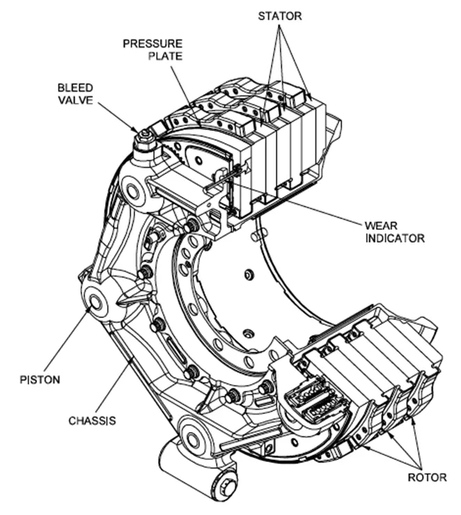
The above figure shows the Gulfstream G450 main landing gear brake assembly.
Spoilers
Spoilers serve several very important functions. In flight, they effectively increase the aircraft’s rate-of-descent without causing an accompanying increase in airspeed. Once the main landing gear is firmly on the runway, the pilot deploys the spoilers to their fully extended position, creating the maximum amount of drag to slow the aircraft from its touchdown speed of approximately 120-to-140 mph to a more proper braking speed of 60-80 mph. Once the aircraft has decelerated to taxi speed, spoilers are stowed.
Part B:
6. A. With necessary assumptions, calculate the force and power required to push / pull an aircraft by a towing vehicle.
Let us the consider the scenario of the Airbus A320-200 (World's most predominantly used Passenger Aircraft).
Weight of Airbus A380= 79 tonnes= 79,000 Kgs
Let us consider the towing vehicle to be Mototok Spacer 8600
Weight of the Mototok Space 8600= 5400 Kgs. (from the data sheet)
Let us analyse various forces to be overcome to push the aircraft.
- Rolling resistance force
Frr=μrr.M.g">Frr=μrr.M.gFrr=μrr.M.g
⇒Frr=μrr.weight">⇒Frr=μrr.weight⇒Frr=μrr.weight
let μrr">μrrμrr=0.002
That implies Frr= 0.002*79000= 158 N
Frr of Mototok towing vehicle= 0.002*5400=10.8 N
- Aerodynamic resistance force:
Let us assume that speed of pushback or pushforward is 5.4 km/hr. (i.e 1.5 m/s) [From the datasheet]
Let,
Drag coefficient (Cd)= 0.025
Air Density ρ">ρρ = 1.125 kg/m^3.
Frontal Area (A): 150 m^2
Velocity (V)= 5.4 kmph or 1.5 m/s
Far=12⋅Cd⋅ρ⋅A⋅v2">Far=12⋅Cd⋅ρ⋅A⋅v2Far=12⋅Cd⋅ρ⋅A⋅v2
⇒Far=12⋅0.025⋅1.125⋅150⋅1.52">⇒Far=12⋅0.025⋅1.125⋅150⋅1.52⇒Far=12⋅0.025⋅1.125⋅150⋅1.52
⇒Far=4.74N">⇒Far=4.74N⇒Far=4.74N
Therefore, airdrag force is 4.74 N
Note: Generally Towing vehicles are designed such that their frontal area is very less. Hence the air drag force due to them is very small and can be neglected.
- Hill climb resistance
The taxiways on the airport are constructed flat. Hence gradient or hill climb force is neglected.
4.) Inertia force of the aircraft
Mass of the aircraft= 79000/9.8= 8061.22 kg
Inertial force of the aircraft= m⋅(vt)">m⋅(vt)m⋅(vt) where t is the towing time.
Let the towing time be 30 seconds.
That implies inertial force of the aircraft is 8061.22*(1.5/30)= 403 N
5.) Inertial force of the Towing Vehicle
Mass of the towing vehicle= 5400/9.8= 551 kg
Inertial force = 551* (1.5/30)= 27.55 N
Therefore, Total force requirement is 158+10.8+4.74+403+27.55= 604.09 N= 610 N (approx)
Power required
P=F⋅v">P=F⋅vP=F⋅v
⇒P=610⋅1.5=915W">⇒P=610⋅1.5=915W⇒P=610⋅1.5=915W
B. Develop the model for the calculated force and power using Simulink.
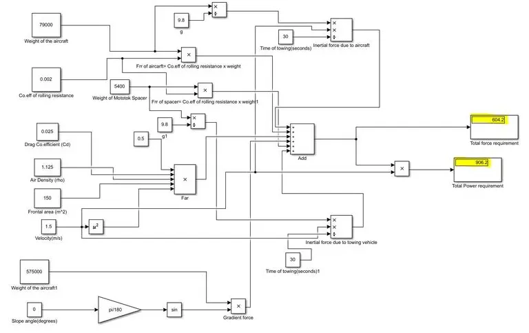
Hence, basic blocks are used to implement the expressions of Rolling resistance force , Aerodynamic drag force ,Gradient force and inertial forces. The forces are then added to find the net force required. The force is then multiplied with the velocity to obtain the total power required
7. A. Design an electric powertrain with type of motor, it’s power rating, and energy requirement to fulfill aircraft towing application in Simulink. Estimate the duty cycle range to control the aircraft speed from zero to highest. Make all required assumptions. Prepare a table of assumed parameters. Draw a block diagram of powertrain.
Block Diagram of power train of towing vehicle:
The above block diagram shows the basic topology of an electric power train. We need to design the each and every component of the power train based on our need. Let us do these calculations below.
Design of Motor:
From the previous question, we could say that the total power required for the towing application is 915W
Let us analyse the torque requirement of the motor:
T=F⋅rG⋅ηgT=F⋅rG⋅ηg
where GGis the gear ratio of the transmission system and ηgηgis the gear efficiency
For Mototok's towing vehicles, G=27 and radius of the wheels (r) = 0.15 m
Assuming efficiency of gear transmission as 95%,
Torque T= (610* 0.15)/(27* 0.95)= 3.567 Nm
ω=PoutToutω=PoutTout
⇒ω=9153.567=256.5⇒ω=9153.567=256.5rad/s= 2450 rpm (approx)
Considering all the above requirements, let us choose the ABB "M2BAX 80MB 2" three phase squirrel cage induction motor.
Motor Specifications:Vbat=PiIiVbat=PiIi
Output Power: 1.1 kW
Rated torque: 3.67 Nm
Rated speed: 2840 rpm.
In our case, the motor needs to generate an output power of 915W. It is given in the data sheet that the efficiency of the motor ABB "M2BAX 80MB 2" at full load is 79.6%= 80% approx
Therefore, Input Power= Output power/ efficiency= 915/0.8= 1143.75 W.
This implies that 1143.75 W of power has to be given from the battery. [ by assuming power converter efficiency as 100%]
Battery Design:
As the rated torque of the motor is almost equal to the required torque, let us assume that the full load current is supplied by the battery to the motor.
Ii=Pi√3⋅Vl⋅cosϕIi=Pi3⋅Vl⋅cosϕ
That implies Ii= 1143.75/(1.732*415*0.83)= 1.917 A [From the data sheet, Line voltage Vl=415V and Power factor at full load is 0.83)
Therefore current supplied by the battery is 1.917 A.
That implies Battery voltage Vbat=PiIiVbat=PiIi
Vbat= 1143.75/1.917= 596.6 Volts
Therefore battery voltage must be 596.6 Volts
In a DC chopper, Vo= D. Vin where D is the duty cycle. Here Max Vo allowed is the voltage rating of the motor.
Vo cannot exceed 415V as it is the rated voltage of the motor. Vin= 596.6 V
=> D_max= 415/596.6=0.695
Therefore the duty cycle can range from 0 to 0.695 to control the speed of the towing vehicle from zero to highest.
Energy requirement of the battery
E=Pi⋅tE=Pi⋅twhere t is the total time time of discharge of battery.
Assuming total time of discharge as 120 seconds, E= 1143.75*120= 137250 J
That implies E= 137250/(3600)= 38.125 Wh
Therefore the minimal rating of the battery must be 38.125 Wh
Assumed Parameters
Note: Some of the parameters are not assumed but taken from the datasheets.
|
Parameter |
Assumed values |
|
Weight of the Aircraft (Airbus A320) |
79000 kg |
|
Weight of the Towing vehicle (Mototok Spacer 8600) |
5400 kg |
|
Co. efficient of rolling resistance (μrrμrr) |
0.002 |
|
Drag co.efficient (Cd) |
0.025 |
|
Air Density ρρ |
1.125 kgm3kgm3 |
|
Frontal area of the aircraft |
150 m^2 |
|
Velocity or Speed of the towing vehicle |
1.5 m/s |
|
time of towing |
30 seconds |
|
Gear ratio of transmission system of Mototok Spacer |
27 |
|
Gear transmission efficiency |
0.95 |
|
Radius of the Towing vehicle wheel |
0.15 m |
|
Gradient of the surface (in degrees) |
0 |
|
Efficiency of the motor |
0.8 |
|
Power factor of the motor |
0.83 |
|
Rated voltage of the motor |
415 V |