Week - 4
Aim-
1. Implement control logic of a “washing machine” using Stateflow as per given sequence:
- If the power supply is available, the system gets activated
- If the Water supply is not available, stop the process & indicate through LED
- Soaking time should be 200s followed by Washing time of 100s.
- Then rinsing happens for next 20s & dryer runs for 50s
After all the processes have completed turn on the finished LED
2. Make a Simulink chart for the “Gear shift” logic as per below conditions:
Speed Range(kmph) Gear
0 to 15 1
16 to 25 2
26 to 40 3
41 to 60 4
Above 61 5
Give speed input while the simulation is running & display the gear number.
Theory...
Stateflow- Stateflow provides a graphical language that includes state transition diagrams, flow charts, state transition tables, and truth tables. You can use Stateflow to describe how MATLAB algorithms and Simulink models react to input signals, events, and time-based conditions. Stateflow enables you to design and develop supervisory control, task scheduling, fault management, communication protocols, user interfaces, and hybrid systems.
With Stateflow, you model combinatorial and sequential decision logic that can be simulated as a block within a Simulink model or executed as an object in MATLAB. Graphical animation enables you to analyze and debug your logic while it is executing. Edit-time and run-time checks ensure design consistency and completeness before implementation.
Cantrol Logic- Cantrol logic is a part of the software program that cantrols its execution. Cantol logic is model system logic using State machine, Flowchart and Truth tables. The cantrol logic has two main charateristics.
- It tries to model a sequence or mode of operation. Eg- In the automobile engine reactes to its throttle differently based on the gear the vehicle is in, or consider a rocket launch which goes to a sequence of stages as the rocket tries to liftoff and travel its distance, similarly robots, though they move continously, they have distinct modes of operation
- It needs to reacts to command from the user and also needs to perform automated tasks which is structured into the program. This logic is typically implemented in program using time-based conditions, boolean logic and reacts to external events.
Program that is found to contain lot of cantrol logic are.
- Supervisory Logic
- Task Scheduling
- Fault Management
Challenges to designing cantrol logic
- Modes of operation are difficult to represent with traditional approaches
- Condition logic can be very complex so, difficult to debug
- Interaction between components and stages is hard to visualize and debug
The solution for above challanges
- State machines are regularly used to represent mode logic
- Flow charts are used to model processes that contains conditions
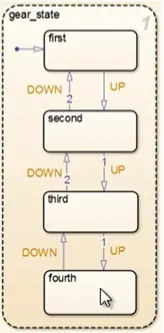
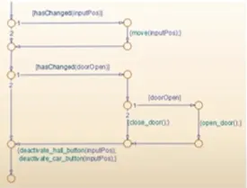
State Machine Flow Chart
- State Machine and flow chart put together can be used to represent cantrol logic in clear and concise way. State flow is tool that can model state machines and flow charts. You can create both graphical and tabular representation of state machine and flow chart.
- In stateflow you can visualize the behaviour of logic by animating it during simulation. Here during the simulation we can see that the states are actually getting highlighted as they become active. The capability to simulate and animate, along with an integrated debugger.
State Machine- A state machine is a behavior model. It consists of a finite number of states and is therefore also called finite-state machine (FSM). Based on the current state and a given input the machine performs state transitions and produces outputs. ... The basic building blocks of a state machine are states and transitions.A finite state machine is a model of a reactive system. The model defines a finite set of states and behaviors and how the system transitions from one state to another when certain conditions are true.
A finite state machine is used to model complex logic in dynamic systems, such as automatic transmissions, robotic systems, and mobile phones.
Examples of operations containing complex logic include:
- Scheduling a sequence of tasks or steps for a system
- Defining fault detection, isolation, and recovery logic
- Supervising how to switch between different modes of operation
A finite state machine can be represented by state charts. State charts provide additional capabilities beyond traditional finite state machines, such as:
- Modeling hierarchical states for large-scale systems
- Adding flow graphs to define complex decision logic
- Defining orthogonal states to represent systems with parallelism
For more information about modeling state machines, see Stateflow
Aerospace and Defense Applications
- Fault detections in Aircraft Cantrol System
- Developing Logic for a Launch Abort System
- Spacecraft Automated landing system
- Mesile Launching and Target System
- Requirements-Based Testing in Aircraft Cantrol Design
Automotive Applications
- Modeling a Fault-Tolerant Fuel Cantrol System
- Automotive Power Train Cantrol System
- Automatic Transmission Cantrol
- Hybrid Electric Vehicle Modeling and Simulation
1. Implement control logic of a “washing machine” using Stateflow as per given sequence:
- If the power supply is available, the system gets activated
- If the Water supply is not available, stop the process & indicate through LED
- Soaking time should be 200s followed by Washing time of 100s.
- Then rinsing happens for next 20s & dryer runs for 50s
Washing Machine and its working princlple
A washing machine is an essential electronic appliance which is present in every households for cleaning or washing cloths.Washing machines make the household tasks so much easier, especially if you have a big family and lots of laundry to do. While using a washing machine may seem so much more straightforward than washing those loads by hand, there is a complex mechanism inside your washer, so find out more about how a washing machine works and more!
Meet the parts of the washer
The washing machine concept is pretty simple – it agitates your clothes in a soapy suds and water to remove any dirt and stains before spinning to drain the water after the cycle. The main components of a washing machine is the drum, which fills up with water, but did you know that washing machines actually have two drums, not one? Your average washing machine is made up of:
- An inner drum- This is where you put the clothes when you’re ready to wash. You’ll notice this drum rotates a bit when you touch it and there are a lot of holes punched into the drum. These allow the water to come in and wash the clothes.
- Paddles- These are ridges that lie on the edge of the drum and help move your clothes around while being washed.
- Agitator- These are more common in top load machines and is a paddle in the middle that helps turn the clothes around in the soapy water.
- The outer drum- This is not obvious when you look inside the washer, but there is another drum that holds the water while the inner drum or agitator rotates. This part is completely water tight to prevent your machine from leaking all over the bathroom or kitchen!
- Thermostat and heating element- These control the temperature of the water and heats up the water to the specified temperature.
- Pump- This removes the water from the drum after the wash.
- Programmer- This controls the washing machine through all the steps from washing to rinsing and spin drying.
- Pipes and valves- These allow the water in and out of the washer.
Programs and why do you need them
Programs, such as delicate wash, colour wash or pre-soak, are one of the features of washing machines, particularly fully automatic washing machine, which gives you the choice when it comes to how you want to wash your clothes. If you need a certain temperature or you’re washing with a certain fabric, then programs help you find the optimal washing conditions for your laundry needs from selecting the right wash temperature to setting up your washing timing.
Semi- vs fully-automatic washing machines
There are many washing machines out there, and the one you choose really depends on your uses for a washing machine, as well as factors such as cost and convenience. A fully-automatic washing machine, like the name says, does everything automatically at the push of a button. A sem-automatic washing machine may be a step up from hand washing, but you may need to do some of the process yourself, like move the wet clothes into the spin dryer.
Front load vs top load
One of the things to know about washing machines is that when it comes to fully-automatic washing machines you get two types of washing machine– one that opens from the top, called a top load washing machine, and one that opens from the side, a front load washing machine. Both machines carry their own washing machine features, along with their pros and cons.
How to install a machine
It’s best to get a plumber to install your machine, but first of all you need to know where to put your washing machine. Taking the washing machine dimensions into account, along with its plumbing needs, especially since a fully-automatic washing machines will need a continuous water supply. Connect and set up your washing machine and make sure all the electronics and pipes are secure before you hit the on button.
How to use a machine
Each washing machine is different. A fully-automatic washing machines, even between top load and front load, or semi-automatic washing machines will work differently when compared to each other. One thing that’s important is the detergent you use, and the question of can you use hand washing powder in a washing machine? will come up. The short answer is no. Hand washing powder creates far too many suds and can leave you with poor laundry results and even affect the performance of the washing machine.
Processes including in working of washing machine
- Soaking- Soaking or Pre-washing, is the first process where water and detergent is mixed thoroughly and the cloths are soaked in this mixture where some amount of dust and dirt from the cloths.
- Washing- During the wash cycle, a large plastic agitator(green) turns around, moving your cloths through the water. When the wash is finished, the pump drains the waste water out from the outer drum.
- Rinsing- The dirty, soapy water is drained, the the washing machine is refilled and cloths are rewashed in clean water. Spin: All the water is drained completely, then cloths are spun very fast and excess water is removed thanks to centrifugal force.
- Drying- During this process a warm dry air is passed through wet washing to extract moisture, then coolingthe now humid air in a heat exchanger to condense the moisture, which is collected in a tank and is drained and rejected out. Then the dry air is reheated.
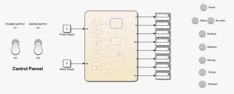
Stateflow model for Automated Washing Machine
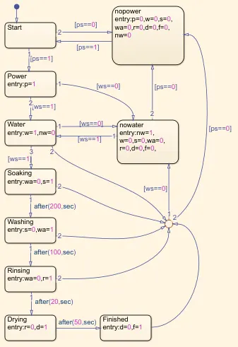
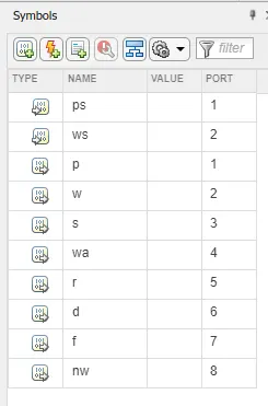
Chart for above model Parameters or symbols used
Construction and Procedure
- Open Simulink in MATLAB for creating models.
- Two constant block is added from the library or by double clicking on th workspace area and searching for the constant block there and name them as Power Supply and Water Supply
- Two toggel switch is added from the dashboard library which is then configured for two constant block which will be acting as the switch to turn the power supply and water supply on or off.
- Chart block is added for the logic that is need to be applied for washing machine. Chart block is a stateflow logic used in this model. After adding open it by double clicking on it.
- A chart block is opened in which the whole UI changes and the model space changes to light yellowish color. In charts logics are applied by using states and connections. Here states are added for each process starting from power. This states works on the ON/OFF condition where when the power is ON ie if ps==1 where, the process moves to its next step or else when the power is OFF it moves to the NOPOWER state where untill the value of ps==1. Here, we used p=1 and the states are connected by the condition that is ps==1
- The process also should continue when water supply is available only. State of water is added with an entry w=1 which is joined with the power state with condition[ws==1]. Another state of no water is added with an entry nw=1,w=0,s=0,wa=0,r=0,d=0,f=0 and this state is joined to water state with condition of ws==0. Condition of ws==1 is also provided with different transition so that when the ws=1 or supply for the water is ON the process moves back to the water state.
- Here state of soaking is added with an entry of s=1 which is connected to water state with a condition of ws==1. When the power and water supply is available, soaking process takes place.
- State for washing is added with an entry s=0,wa=1. This state is joined to the state of soaking with the condition, after 200 seconds. This can be given by after(200,sec).
- State for rinsing is added with the entry wa=0,r=1 which is joined to the previous state (washing) by using the condition 100 seconds. This can be given by after(100,sec).
- State for drying is added with the entry r=0,d=1 which is joined to the previous state (rinsing) by using the condition 20 seconds. This can be given by after(20,sec).
- State for finished is added at last with the entry d=0,f=1 which is joined to the previous state (drying) by using the condition 50 seconds. This can be given by after(50,sec).
- After this every states are bypassed provided by the junction and transition and is connected to the nopower and nowater state by using the condition of ps==0, ws==0 respectively so that if the user or switch the power or water supply off in between the process, it turns into off mode.
- Open sybols and parameters pane for denoting input and output for the chart which can be found in prepare section in menu bar.
- Given input data for ps and ws whereas output data for p, w, s, wa, r, d and f.
- Come to the main model from the chart. Here we can observe that the input and output ports are available on the chart blocks. Connect the two constant blocks to the output port and display block to all output port.
- Name each ports or displays with the process that defines and connect all lamps and switch based on the above diagram with 0 for red light and 1 for green lamp.
- This model is made to simulate for infinite time so that we can understand and note down its process and working.
- In above case we can see that the toggle switchs is in OFF postion, so the power as well as water supply is turned off that why the lights of the lamp is also turned OFF
- In below condition the power supply is turned ON but water supply remains of in right hand side we can see that the Power lamp is turned ON and shows green light whereas as the water supply is remain in OFF position the No water lamp is turned ON with a red light.
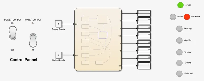
- When switches for both power supply and water supply is on the system activates and the process for the washing of cloths goes on from washing to drying and after whole process gets completed the finished lamp with green coloured light lights up(given in gif below).
2. Make a Simulink chart for the “Gear shift” logic as per below conditions:
Speed Range(kmph) Gear
0 to 15 1
16 to 25 2
26 to 40 3
41 to 60 4
Above 61 5
Give speed input while the simulation is running & display the gear number.
Transmission of gear box-Construction, Principle and working
All the drive-train components that help transmit the engine power to the wheels are a part of the ‘Transmission’ system. Of which the gearbox is an integral part. These components include the clutch, gearbox, couplings, propeller shaft, axle shafts, and differential. In general, the term 'Transmission' usually refers to the car’s gear box. Some car designs integrate the gear box and differential assembly into a single unit called ‘Transmission’ or 'Trans-Axle.
A gear box contains gears of different sizes. This is mainly because of the vehicle's varying demands in terms of the torque required at the wheels depending upon the road, terrain & load. E.g., if a vehicle is climbing a slope, it needs higher torque than cruising on a straight road.
The first gear is the biggest in size in a gear box and provides maximum torque output while producing minimum speed. Hence, it is used when climbing slopes. All the gears between 1st and last gear vary in size, in a decreasing ratio. Thus, it provides a varying combination in terms of pulling ability and speed. So, the vehicle could be driven smoothly without any drop in its acceleration. The gear box basically improves the vehicle's driveability in all conditions.
Generally, there are two sets of gears in a conventional gear box – the input & the output. The input gears are fixed on the countershaft, making it a single unit. It drives the individual gears on the main shaft, which rotate freely on the bearings. Thus, the gearbox passes the drive to the wheels depending upon the gear which engages on the main-shaft. When you push the shifter-sleeve towards the desired gear, that gear locks onto the main-shaft and rotates it. Thus, the main shaft rotates at the engaged gear's speed and provides the output as per the engaged gear’s ratio.
Speed vs Traction- You need both speed as well as traction while driving an automobile. The gears in the gearbox help you choose either of them depending on the driving conditions. The lower gear, i.e., 2nd and 1st gear, will give you the greatest traction, while the higher gears, i.e., 5th and 6th (if available), will give you the highest speed. The number of gears in the gearbox provides the perfect combination of traction and speed. Thus, it helps the driver/rider choose the most appropriate combination to enhance efficiency at all times. Hence, choosing the right gear according to road and load conditions is very important. With short gearing, you get better acceleration or pick-up, while tall gearing gives you higher top speed.
The following blocks are used to model the gear shifting mechanism
- Slider switch
- Constant
- Stateflow chart
- Display
- Lamps
is given blow with the stateflow chart and its parameters
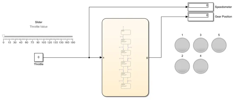
The stateflow model of gear shifting with vehicle dashboard
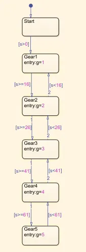
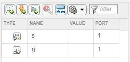
Chart for above model Parameters or symbol for above model
Here consider the vehicle is in OFF position we can see that all the lamps in the dashboard is also remains OFF untill the vehicle is started
Here the slider is used to simulate the throttle or accelerator mechanism. and display is used for displaying the velocity and the gear position.
Case 1. When the throttle is applied and spead is between 0-15kmph the 1st gear is applied and the 1st gear lamp in green lights up automatically based on the logic initiated.
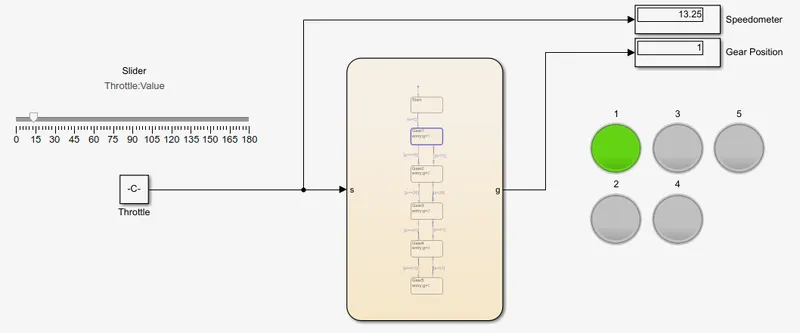
Case 2. When spead reaches to 16-25 kmph the 2nd gear position lamp lights up as shown.
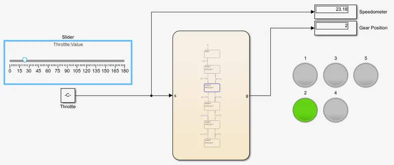
Case 3. When spead reaches to 26-40 kmph the 3rd gear position lamp lights up as shown.
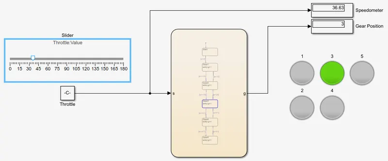
Case 4. When spead reaches to 41-60 kmph the 4th gear position lamp lights up as shown.
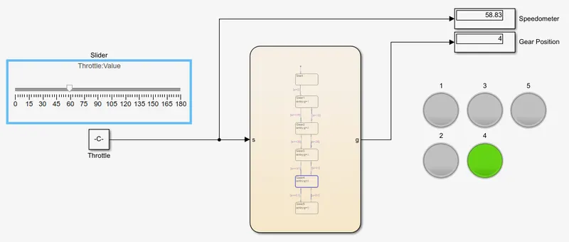
Case 5. When spead reaches to above 60kmph the 5th gear position lamp lights up as shown.
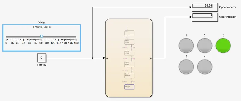
Here we can see that the lamp is lit according to the gear it is in current running shows which depends on the velocity of the vehicle that we selected using slider.
Conclusion- Here from stateflow and flowchart we models an automatic washing magine and gear shifting.