Final Project: Design of an Electric Vehicle
Aim- Final Project: Design of an Electric Vehicle
Main Objective- Create a MATLAB model of electric car which uses a battery and a DC motor. Choose suitable blocks from Powertrain block set. Prepare a report about your model including following:
Objectives:
1. System level configurations
2. Model parameters
3. Results
4. Conclusion
Theory
The world is changing, and the automobile industry is adopting electric vehicle systems much faster than ever before. The electric vehicle system achieved a lot in the last decade and now it is on track to fulfil the goal of a green transportation system with efficient and sustainable energy sources. The total number of electric cars worldwide had only 0.02 million in 2010 which is increased to more than 7 million in 2020. Imagine the same growth rate for the decade 2020-2030, and then one can realize the real future of the electric vehicle market worldwide.
An electric vehicle (EV) is a vehicle that uses one or more electric motors for propulsion. It can be powered by a collector system, with electricity from extravehicular sources, or it can be powered autonomously by a battery (sometimes charged by solar panels, or by converting fuel to electricity using fuel cells or a generator).[1] EVs include, but are not limited to, road and rail vehicles, surface and underwater vessels, electric aircraft and electric spacecraft.
EVs first came into existence in the mid-19th century, when electricity was among the preferred methods for motor vehicle propulsion, providing a level of comfort and ease of operation that could not be achieved by the gasoline cars of the time. Internal combustion engines were the dominant propulsion method for cars and trucks for about 100 years, but electric power remained commonplace in other vehicle types, such as trains and smaller vehicles of all types.
In the 21st century, EVs have seen a resurgence due to technological developments, and an increased focus on renewable energy and the potential reduction of transportation's impact on climate change and other environmental issues. Project Drawdown describes electric vehicles as one of the 100 best contemporary solutions for addressing climate change.
Government incentives to increase adoption were first introduced in the late 2000s, including in the United States and the European Union, leading to a growing market for the vehicles in the 2010s. Increasing public interest and awareness and structural incentives, such as those being built into the green recovery from the COVID-19 pandemic, is expected to greatly increase the electric vehicle market. The International Energy Agency said in 2021 that governments should do more to meet climate goals, including policies for heavy electric vehicles. Electric vehicle sales may increase from 2% of global share in 2016 to 30% by 2030. Much of this growth is expected in markets like North America, Europe and China; a 2020 literature review suggested that growth in use of electric 4-wheeled vehicles appears economically unlikely in developing economies, but that electric 2-wheeler growth is likely. There are more 2 and 3 wheel EVs than any other type.
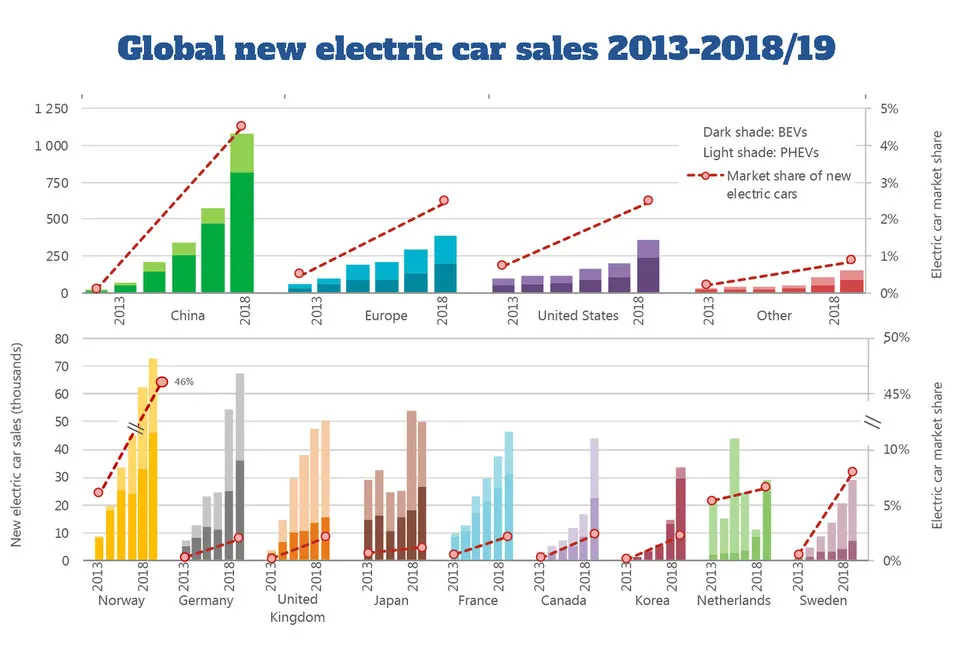
A battery electric vehicle (BEV), pure electric vehicle or all-electric vehicle is a pure form of electric vehicle which neither uses gasoline mor diesel for its propulsion. and exclusively uses chemical energy which is stored inside a module of rechrgeable battery packs, with no secondary source of propulsion. BEVs use electric motors and motor controllers instead of internal combustion engine, fuel cell or fuel tank. BEVs are not limited to cars, motocycles, cycles, scooters, akateboards, trains.
The power of a vehicle's electric motor is measured in kilowatt (kW) as in the power calculated in convention IC engines. 100kW is roughly equal to 134 horse power but electric motor can deliver their maximum torque over a wide RPM range. This means that the performance of the electric vehicle with 100kW motor exceeds that of a vehicle with 100kW internal combustion engine, which can only deliver its maximum torque within a limited range of engine speed. Some amount of electrical energy is lost during the process of conversion of electrical energy to mecanical work. Approximately 90% of the energy from the battery is converted into mechanical with minimum losses. Mostly, the losses occur in motor and drivetrain.
Usually, DC current is fed into the DC/AC converter also called as inverter which converts the DC current to AC, and the AC current is feeded to 3 phase AC induction motor. This is the case for running the vehicle which includes AC induction motor. For smaller and light duty vehicles DC motors are usually used and fpr heavy duty vehicles like truck or train AC motor is usually preferred. In some cases, universal motorsare used, and then AC or DC maybe employed. In recent production vehicles, various motor types have been implemented: for instance induction motor in tesla model S and roadster, BLDC motor in Tesl model 3 and permanent magnet DC machines in the Nissan Leaf and Chevrolet Bolt.
Most large electric transport systems are powered by stationary sources that are directly conneted to the vehicle through the wires. Electric traction allows the use of regenerative braking, in which the motor are used as brakes and act as a generator tat transforms the motion of usually the train into the electrical power then the generated power is feeded back into the lines. This is particularly advantageous in mountainous region of operation where descending vehicle can produce large poertion of power.
There needs to be more convinient ways for the consumers to be able to charge their vehicle, there needs to be several charging stationson highwaysand this can be supported if most of the houses is provided with solar powered charging panel for their EVs where they can charge their vehicle on the go. EVs cost more than conventional vehicle because of high cost of batteries and other electrical components.
Why Electric Vehicles:
- Low maintanence
- Eco friendly as there is no emission
- Silent operation
- Low running cost
What makes the Electric vehicles
An electric vehicle is usually consists of many components and a large cluster of wires connecting them all. But there are few basic bare minimum materials for an electric car which is shown in diagram below:
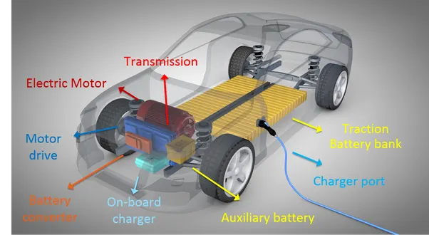
In this report I will be modelling a fully electric vehicle with DC motor and battery system using Simulink. The model will run for a drive cycle and measure the velocity characteristics, current, and state of charge characteristics of the battery system. For the modelling of the same, I need some of the blocks which are listed below
System Level Configuration.
For modelling the whole vehicle in Simulink, we need to model the compnent seperately and make them work together. All the main components are available in the library of Simulink. So. we add the components and configure the parameters to fit the orking requirements of the model.
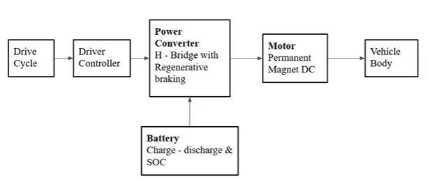
- Drive Cycle
- Driver Controller
- Power Converter (H-Bridge)
- Controlled PWM Voltage
- DC Motor
- Battery Source
- Vehicle & Tires
In the figure below, we have created a simulation model of the fully electric vehicle using various drive cycles by using powertrain blockset available in Simulink library. First, there is an input port where you have to connect the drive cycle source block which provides the reference for the longitudnal driver which compares the two speed and gives the accelerator and brake inputs or commands to the motor controller block. Battery blck and vehicle with tire block is further connected to the scope and display for displaying the status of its working parameters.
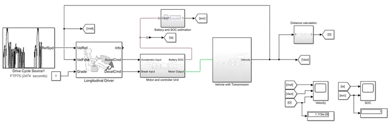
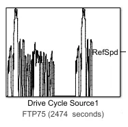
1. Drive Cycle Source
Generates a standard or user-specified longitudinal drive cycle. The block output is the vehicle longitudinal speed. You can import drive cycles fromas predefined sources, Workspace variables, including arrays and time series objects, mat, xls, xlsx, or txt files. Use the fault tracking parameters to identify drive cycle faults within specified speed and time tolerances.
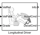
2. Longitudinal Driver
A parametric longitudinal speed tracking controller for generating normalized acceleration and braking commands based on reference and feedback velocities. Use the external actions to input signals that can disable, hold, or override the closed-loop commands determined by the block. The block uses this priority for the input commands: disable, hold, override.
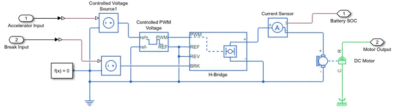
3. Motor & Controller Unit
- Controlled Voltage Source- The block represents an ideal voltage source that is powerful enough to maintain the specified voltage at its output regardless of the current passing through it. The output voltage is V = Vs, where Vs is the numerical value presented at the physical signal port.
- Controlled PWM Voltage- This block creates a Pulse-Width Modulated (PWM) voltage across the PWM and REF ports. The output voltage is zero when the pulse is low, and is equal to the Output voltage amplitude parameter when high. Duty cycle is set by the input value. Right-click the block and select Simscape->Block choices to switch between electrical +ref/-ref ports and PS input u to specify the input value. At time zero, the pulse is initialized as high unless the duty cycle is set to zero or the Pulse delay time is greater than zero. The Simulation mode can be set to PWM or Averaged. In PWM mode, the output is a PWM signal. In Averaged mode, the output is constant with value equal to the averaged PWM signal.
- H-Bridge- This block represents an H-bridge motor drive. The block can be driven by the Controlled PWM Voltage block in PWM or Averaged mode. In PWM mode, the motor is powered if the PWM port voltage is above the Enable threshold voltage. In Averaged mode, the PWM port voltage divided by the PWM signal amplitude parameter defines the ratio of the on-time to the PWM period. Using this ratio and assumptions about the load, the block applies an average voltage to the load that achieves the correct average load current. The Simulation mode parameter value must be the same for the Controlled PWM Voltage and H-Bridge blocks.
- Current Sensor- The block represents an ideal current sensor, that is, a device that converts current measured in any electrical branch into a physical signal proportional to the current. Connections + and - are conserving electrical ports through which the sensor is inserted into the circuit. Connection I is a physical signal port that outputs current value.
- DC Motor- This block represents the electrical and torque characteristics of a DC motor. The block assumes that no electromagnetic energy is lost, and hence the back-emf and torque constants have the same numerical value when in SI units. Motor parameters can either be specified directly, or derived from no-load speed and stall torque. If no information is available on armature inductance, this parameter can be set to some small non-zero value. When a positive current flows from the electrical + to - ports, a positive torque acts from the mechanical C to R ports. Motor torque direction can be changed by altering the sign of the back-emf or torque constants.
4. Battery SOC estimate
- Battery- This block models a battery. If you select Infinite for the Battery charge capacity parameter, the block models the battery as a series internal resistance and a constant voltage source. If you select Finite for the Battery charge capacity parameter, the block models the battery as a series internal resistance plus a charge-dependent voltage source defined by: V = Vnom*SOC/(1-beta*(1-SOC))
where SOC is the state of charge and Vnom is the nominal voltage. Coefficient beta is calculated to satisfy a user-defined data point [AH1,V1].
-
Controlled Current Source- The block represents an ideal current source that is powerful enough to maintain the specified current through it regardless of the voltage across it. The output current is I = Is, where Is is the numerical value presented at the physical signal port.
- Electric Reference- Electrical reference port. A model must contain at least one electrical reference port (electrical ground).
- Rate Transition- Handle data transfer between different rates and tasks.
- Gain- Element-wise gain (y = K.*u) or matrix gain (y = K*u or y = u*K).
- Descrete Time Integrator- Discrete-time integration or accumulation of the input signal.
- Sum- Add or subtract inputs. Specify one of the following:
a) character vector containing + or - for each input port, | for spacer between ports (e.g. ++|-|++)
b) scalar, >= 1, specifies the number of input ports to be summed.
When there is only one input port, add or subtract elements over all dimensions or one specified dimension
- Constant- Output the constant specified by the 'Constant value' parameter. If 'Constant value' is a vector and 'Interpret vector parameters as 1-D' is on, treat the constant value as a 1-D array. Otherwise, output a matrix with the same dimensions as the constant value.
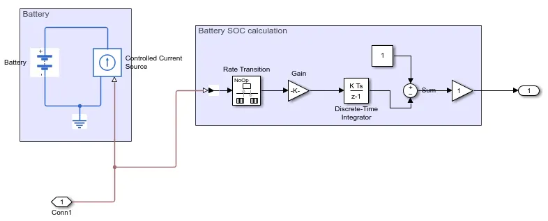
The SOC estimate block is connected with the rate trasition, the gain considered at (1/80*3600), the sum block, the discrete time integrator, and the constant block. This gives us the battery SOC estimate. The usage of the operating sources the more the SOC goes down in the specified interval.
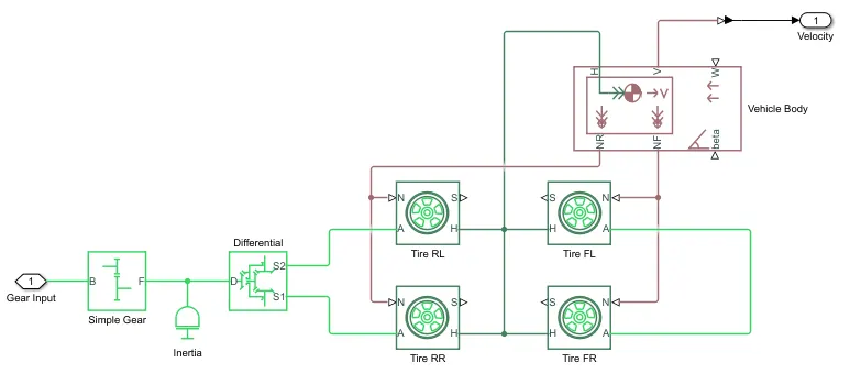
5. Vehicle with Transmission Subsystem
This subsystem includes one simple gear, differential, vehicle body and 4 tires(magic formula) and all are connected as shown in figure below.
- Simple Gear- For engaging the correct gear at the right duration when required
- Inertia- The block represents an ideal mechanical rotational inertia. The block has one or two mechanical rotational conserving ports. The difference is purely graphical, as the ports are rigidly linked. The block positive direction is from its port to the reference point. This means that the inertia torque is positive if the inertia is accelerated in the positive direction.
- Differential- Represents a differential which is arranged as a planetary bevel gear train equipped with an additional bevel gear transmission between the driveshaft and the carrier. The pinion gear of this transmission is attached to the driveshaft while the large bevel crown gear is affixed to the carrier. Compliance is not modeled in this block. Optionally include inertia and losses from gear meshing and viscous bearing friction.
- Vehicle Body- Represents a two-axle vehicle body in longitudinal motion. The block accounts for body mass, aerodynamic drag, road incline, and weight distribution between axles due to acceleration and road profile. The vehicle can have the same or a different number of wheels on each axle. Optionally include pitch and suspension dynamics or additional variable mass and inertia. The vehicle does not move vertically relative to the ground.
- Tire(Magic Formula)- Represents the longitudinal behavior of a highway tire characterized by the tire Magic Formula. The block is built from Tire-Road Interaction (Magic Formula) and Simscape Foundation Library Wheel and Axle blocks. Optionally, the effects of tire inertia, stiffness, and damping can be included.
6. Distance Calculation Block
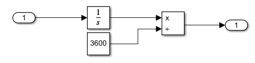
Mathematical blocks and scope is used to measure the distance travelled by the vehicle. First we had to implement the integater block to indicate the veloctiy signal that is output from the velocity of the vehicle. Dividen block along with the constant block having a value of 3600 is used to divide the integrated speed. This will give the distance travelled in kilometers.
Result
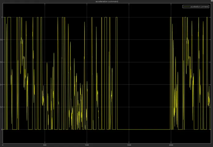
1. Scope result from the acceleration input
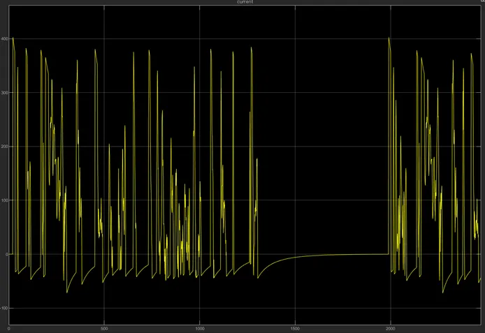
2. Scope result for the current drawn from the battery pack
3. Here for the reference velocity the we can see that the feedback velocity is tracing the same path.
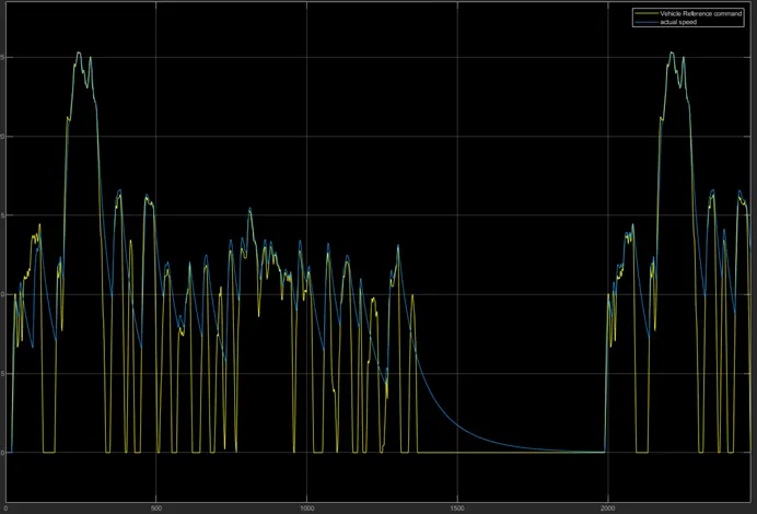
Conclusion- Here from the result we can conclude that the actual speed of the vehicle is tracing the refered speed from the drive cycle. Here we can also say that to reduce the difference between the actual vehicle velocity and the reference velocity we can optimise or change the parameters including battery voltage or motor loads.