Project
AIM- To prepare a technical report of simulation of BAJA All Terrain Vehicle (ATV) under different conditions
MAIN OBJECTIVE-
- Carry out System-level Simulation(SLS) of an all-terrain vehicle and prepare a technical report explaining the model properties and comments on the results.
- To understand the use of lookup tables & Dashboard blocks that enhance the performance of a Simulink Model.
Theory
System Level Simulation- System level simulation or SLS is a set a texhnique that uses a computers to imitate the operations of various real world tasks or process through simulation. Computers are used to generate numeric models for the purpose of describing or displaying complex interaction among multiple variables within a system.It is a collection of practical methods used in the fields of system engineering, in order to simulate, for studying its global behaviour.
All-Terrain Vehicle- An All-terrain vehicles or ATV also known as Light Utility Vehicle or LUV is defined as a motorized off-highway or off-road vehicle designed to travel on four low-pressure or non-pneumatic tires, having a seat designed to be straddled by the operator and handlebars for steering control.
ATVs are subdivided into two types as designated by the manufacturer. Type I ATVs are intended by the manufacturer for use by a single operator and no passenger. Type II ATVs are intended by the manufacturer for use by an operator and a passenger, and are equipped with a designated seating position behind the operator. Similarly, riders must also consider the various ATV sizes. The rider sits on and operates these vehicles like a motorcycle, but the extra wheels give more stability at slower speeds. Although most are equipped with three or four wheels, six-wheel models exist for specialized applications. Multiple-user analogues with side-by-side seating are called utility-terrain vehicles(UTV) or side by sides to distinguish the classes of vehicle. Both classes tend to have similar powertrain parts.
ATVs, or all terrain vehicles, come in a variety of forms. Some are designed for work, while others are geared towards play. ATVs can accommodate anywhere from one to four people depending on the vehicle.
-
Sports ATVs
Sport ATVs are for the thrill seekers out there. Built for speeding, sliding, and swerving, you’re guaranteed to feel the wind in your face on one of these vehicles. Under your helmet, of course. These ATVs are stacked with powerful engines, long travel suspension, and excellent handling. Whether you’re on a desert trail, in sand dunes, or on a track, sport ATVs offer an exhilarating experience that allows the rider to feel connected with the vehicle.
-
Side-by-side ATVs
These ATVs are called side-by-sides because of the two front seats, and sometimes two back seats. Unlike utility or sport ATVs, side-by sides have a steering wheel rather than handle bars, foot pedals, seat belts, and a roll bar. You and your passengers sit inside the vehicle, just like a car. The difference is that side-by-sides are beefed up to conquer off-road terrain. You can spot side-by-sides in snow, desert, and dunes; with this type of ATV, the world is your playground!
-
Utility ATVs
Utility ATVs have engines that are powerful enough to navigate a variety of terrains, but not powerful enough to match up to a sport ATV. They’re primarily used for heavy-work purposes, like hauling cargo or plowing fields or snow. Although they’re not as fast or agile as sport ATVs, utility ATVs comfortably fit two people and have better ground clearance. Since your utility ATV isn’t being ripped around at top speeds, they tend to require less maintenance and last longer than their thrill-seeking cousin.
-
Youth ATVs
Riding is no longer limited to grown folk! In this day and age, priceless memories can be made as you tear through the dirt with your mini-me by your side. And don’t worry, you don’t have to sacrifice safety or your peace of mind. Youth ATVs are tailored to your child’s size and level of experience. Kids as young as four years old can begin with electric starts and automatic clutches to teach them the feel for the different gears and how to shift through them. However coordinated your youth, there’s an ATV fit for them.
Continously Variable Gear- Continously variable gear or CVT is an automatic transmission that can change seemlessly through a continous range of gear ratio. It works on the principle of built and pulley mechanism. It does not use gears like a conventional transmission. Rather it uses two pulleys which is coupled to engine and transmission shatf respectively and both pulleys are connected by a belt in such a way that the power from the engine is transfered to the transmission shaft and thereby to the wheen axel assembly. The flexibility of a CVT with suitable control may allow the engine to operate at a constant RPM while the vehicle moves at varying speeds.
The most common type of CVT uses a v-belt which runs between two variable-diameter pulleys. The pulleys consist of two cone-shaped halves that move together and apart. The V-belt runs between these two halves, so the effective diameter of the pulley is dependent on the distance between the two halves of the pulley. The V-shaped cross section of the belt causes it to ride higher on one pulley and lower on the other; therefore, the gear ratio is adjusted by moving the two sheaves of one pulley closer together and the two sheaves of the other pulley farther apart.As the distance between the pulleys and the length of the belt does not change, both pulleys must be adjusted (one bigger, the other smaller) simultaneously in order to maintain the proper amount of tension on the belt. Simple CVTs combining a centrifugal drive pulley with a spring loaded driven pulley often use belt tension to effect the conforming adjustments in the driven pulley. The V-belt needs to be very stiff in the pulley's axial direction in order to make only short radial movements while sliding in and out of the pulleys.
The radial thickness of the belt is a compromise between maximum gear ratio and torque. Steel-reinforced V-belts are sufficient for low-mass, low-torque applications like utility vehicles and snowmobiles, but higher-mass and -torque applications such as automobiles require a chain. Each element of the chain must have conical sides that fit the pulley when the belt is running on the outermost radius. As the chain moves into the pulleys the contact area gets smaller. As the contact area is proportional to the number of elements, chain belts require many very small elements.
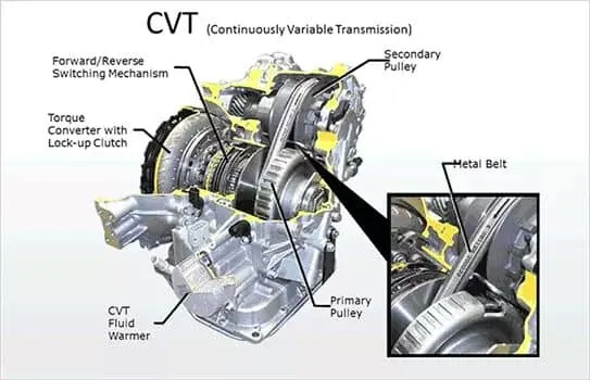
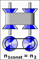
Continous Variable Transmission Mechanism of Continous Variable Gear
A belt-driven design offers approximately 88% efficiency, which, while lower than that of a manual transmission, can be offset by enabling the engine to run at its most efficient RPM regardless of the vehicle's speed. When power is more important than economy, the ratio of the CVT can be changed to allow the engine to turn at the RPM at which it produces the greatest power.In a chain-based CVT, numerous chain elements are arranged along multiple steel bands layered over one another, each of which is thin enough to easily bend. When part of the belt is wrapped around a pulley, the sides of the elements form a conical surface. In the stack of bands, each band corresponds to a slightly different drive ratio, and thus the bands slide over each other and need sufficient lubrication. An additional film of lubricant is applied to the pulleys. The film needs to be thick enough to prevent direct contact between the pulley and the chain, but thin enough to not waste power as each chain element enters it.
Some CVTs transfer power to the output pulley via tension in the belt (a "pulling" force), while others use compression of the chain elements (where the input pulley "pushes" the belt, which in turn pushes the output pulley). It can optimise engine speed in a variety of driving condition. That means low gear can provide better acceleration and traction whereas higher gear can maximize fuel economy and stability.
Here three models of BAJA ATV are studied one by one and reports are made based on the system level simulation done by me. These models are
- BAJA ATV with CVT using Signal Builder
- BAJA ATV with CVT with Dashboard
- BAJA ATV with CVT using Lookup Table
Blocks used in the three simulink Model
1. VARIABLE TRANSMISSION RATIO Block
It represents a variable ratio gearbox such as implemented by mechanical belt CVT, electric, or hydraulic transmissions. The physical signal input r defines the ratio of input to output angular shaft velocities. Connections B (base) and F (follower) are mechanical rotational conserving ports. Specify the relation between base and follower rotation directions with the Output shaft rotates parameter.
2. ENGINE Block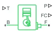
Represents a system-level model of spark-ignition and diesel engines suitable for use at initial stages of modelling when only the basic parameters are available. Optional idle speed and red line controllers are included. The throttle input signal T lies between zero and one and specifies the torque demanded from the engine as a fraction of the maximum possible torque. Connections F and B are mechanical rotational conserving ports associated with the engine crankshaft and engine block, respectively. Connections P and FC are physical signal output ports through which engine power and fuel consumption rate are reported.
3. IDEAL ROTATIONAL MOTION SENSOR Block
This block measures angular velocity or angle in a mechanical rotational network. The sensor is ideal since it does not account for inertia, friction, delays, energy consumption, and so on. The physical signal ports W and A report the angular velocity and angle, respectively, of port R relative to port C. The measured angular velocity is positive when the angular velocity at port R is greater than the angular velocity at port C.
4. VEHICLE BODY Block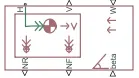
Represents a two-axle vehicle body in longitudinal motion. The block accounts for body mass, aerodynamic drag, road incline, and weight distribution between axles due to acceleration and road profile. The vehicle can have the same or a different number of wheels on each axle. Optionally include pitch and suspension dynamics or additional variable mass and inertia. The vehicle does not move vertically relative to the ground.
Connection H is the mechanical translational conserving port associated with the horizontal motion of the vehicle body. The resulting traction motion developed by tires should be connected to this port. Connections V, NF, and NR are physical signal output ports for vehicle velocity and front and rear normal wheel forces, respectively. Wheel forces are considered positive if acting downwards. Connections W and beta are physical signal input ports corresponding to headwind speed and road inclination angle, respectively. If variable mass is modeled, the physical signal input ports CG and M are exposed. CG accepts a two- element vector representing the x and y distance offsets from vehicle CG to additional load mass CG. M represents the additional mass. If both variable mass and pitch dynamics are included, the physical signal port J accepts the inertia of the additional mass about its own CG.
5. DOUBLE SHOE BRAKE Block
Represents a brake arranged as two pivoted rigid shoes symmetrically installed inside or outside a drum and operated by one actuator. The actuator force causes the shoes to exert a friction torque on a shaft connected to the drum.Connection S is a conserving rotational terminal associated with the drum shaft. Connection F is a physical signal port representing the force input to the actuator. Positive force creates friction torque that resists shaft rotation. Optionally include thermal effects and expose thermal conserving port H by setting Thermal port to Model.
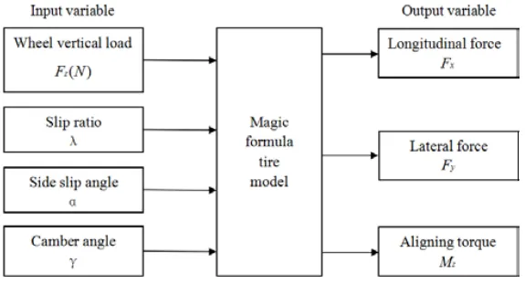
6. TIRE(MAGIC FORMULA) Block
Represents the longitudinal behavior of a highway tire characterized by the tire Magic Formula. The block is built from Tire-Road Interaction (Magic Formula) and Simscape Foundation Library Wheel and Axle blocks. Optionally, the effects of tire inertia, stiffness, and damping can be included.
Connection A is the mechanical rotational conserving port for the wheel axle. Connection H is the mechanical translational conserving port for the wheel hub through which the thrust developed by the tire is applied to the vehicle. Connection N is a physical signal input port that applies the normal force acting on the tire. The force is considered positive if it acts downwards. Connection S is a physical signal output port that reports the tire slip. Optionally expose physical signal port M by setting Parameterize by to Physical signal Magic Formula coefficients. Physical signal port M accepts a four element vector corresponding to the B, C, D, and E Magic Formula coefficients.
An empirical equation based on four fitting coefficients. The block can model tire dynamics under constant or variable pavement conditions. The general form of the Magic Formula,
`y=D*sin{C*arctan[Bx-E*(arctan(Bx))]}`
where B, C, D, and E or stiffness, shape, peak, and curvature represent fitting constants which are four dimensionless coefficients and y is a force or moment resulting from a slip parameter x.
Subsystem used in the three Simulink Model
1. ENGINE SENSOR Subsystem- This sensor consist of an rotational motion sensor block which is used as an RPM sensor. Here the port W is provided a connection with a scope which gives the plot of the angular velocity whereas the port R is connected to the engine crankshaft of engine block and input shaft of CVT subsystem.
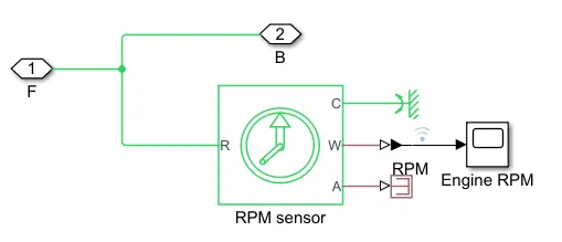 Fig.-1
2. CVT Subsystem- To facilitate the step-less design of the CVT, a variable ratio gear is implemented in the model and the input to this block will decide the actual gear ratio. Both the base and the follower (primary and secondary) are given inertia elements to make the model more realistic. Rotational motion sensors are connected to measure the rpm of both sides. Here the part of input shaft terminal is connected to output of the engine sensor and the output shaft terminal is connected to the input of the simple gear.
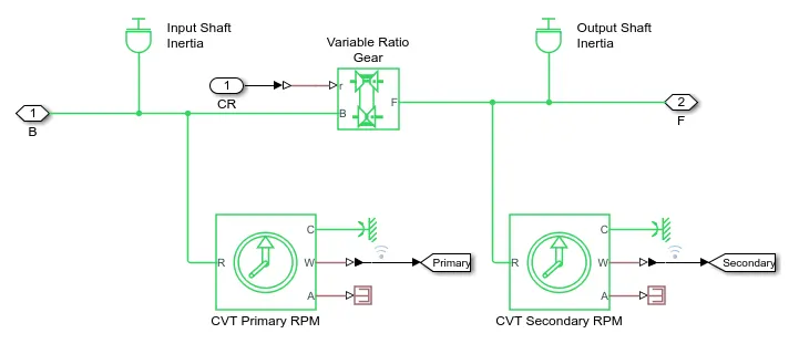 Fig.- 2
3. VEHICLE BODY Subsystem- The vehicle body is defined to have a mass of 250kg mass. The four wheels are connected accordingly Here the port A of the two tire(Magic Formula) is connected to NR and two tire is connected to the NF of the vehicle and RPM of the secondary of CVT and brake input is given to the subsystem as shown in the subsystem below. The vehicle body is given zero inclination and wind velocity. The velocity is taken to the scope by using an Outport (and goto block outside the subsystem) block.
Vehicle body :
Initial engine rpm: 2100 rpm
Mechanical rotation for driven and driver pulley =0.8 and 0.7
Mass of the vehicle = 250 kg
Front and rear axle with 4 wheels
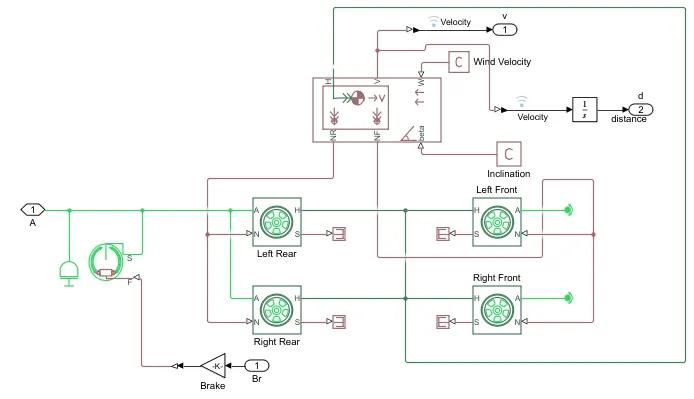 Fig.- 3
CASE 1. BAJA ATV with CVT using Signal Builder
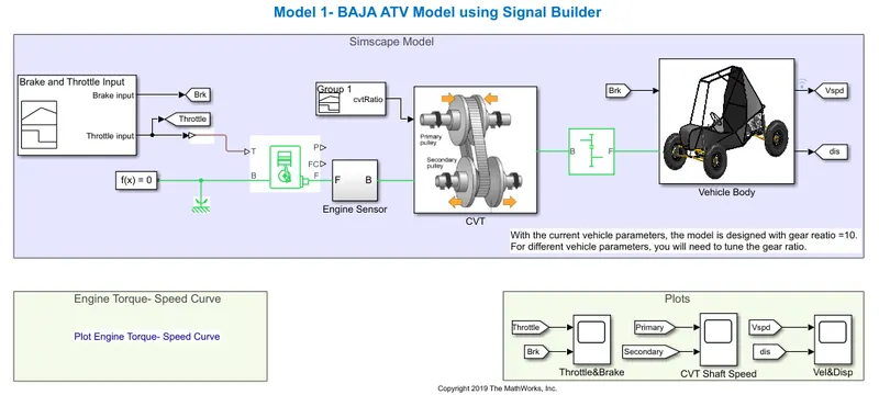 Fig.- 4
In Model 1 that we can see in Fig.-4 is the model of Baja ATV which consists of Signal builder, generic engine, motion sensors, vehicle transmission, vehicle body,tyres and solver configuration blocks etc., as shown in figure-1. The CVT subsystem includes Transmission block, input and output shaft inertia and motion sensors as shown in figure-2. The vehicle body subsystem includes vehicle body block, double drum brake and tyres as shown in figure-3. The initial engine speed is given as 2100 rpm, mechanical rotation for driven pulley and driver pulley as 0.8 & 0.7 respectively. The mass of the vehicle as 250kg and 2 axles which connects 4 wheel accordingly.
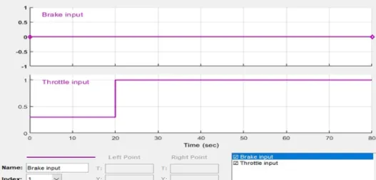
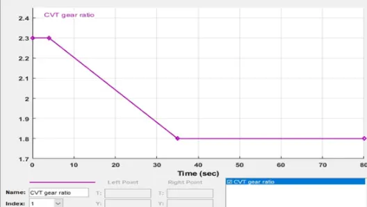 Fig.-5 Fig.-6
 Fig.-7
The signal builder is used as input for brake, throttle and gear ratio. Brake input is maintained as 0 for overall simulation. The throttle input is given as 0.3 for20 secs and increases to 1 for overall simulatuion. The throttle valve is mainly to control the flow or amount of fuel into the engine, if the throttle value increases the flow of fuel increases to the IC engine which inturn increases the power of the engine. The gear ratio is maintained as 2.3 for 5 secs and linearly decreases to 1.8 and maintained constant for overall simulation as shown in figure (4 - 5).
Result for CASE 1
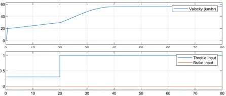
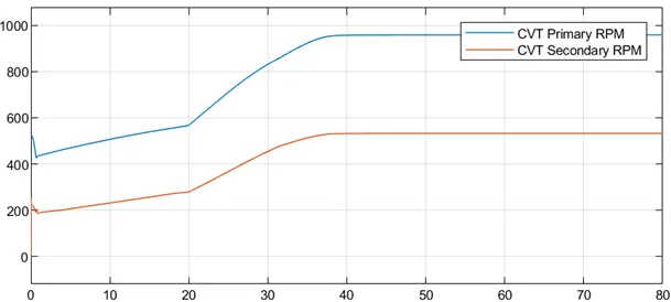 Fig.-7 Fig.-8
After performing the system level simulation for the model 1 we get the graph for variation of velocity and shaft RPM which can be seen in above plots(Fig.-7 and Fig.-8).
In Fig.-7, the brake is maintained as constant and increase in throttle which shows increase in velocity. The flow of fuel is increses when the throttle increases from 0.3 to 1, thus the power in the engine increases. The torque reaches approximately 7N-m at 1.8 gear ratio, which defines that gear ratio is directly proportional to the torque. By this gear ratio, the speed & velocity can achieve maximum.
In Fig.-8. the primary shaft reaches high speed and secondary shaft as low rotational speed because the radius of the primary shaft as more than the secondary shaft, the speed is directly proportional to the radius of the shaft. As the radius increases the speed of the shaft also increases. The primary shaft speed increases by increasing throttle and decreasing by increasing brake input value, which defines that the throttle can flow more amount of fuel which increases the power of the engine and similar to the secondary shaft. The radius of the primary shaft as more than the secondary shaft, the speed is directly proportional to the radius of the shaft. As the radius increases the speed of the shaft also increases.
Here the ratio is determined by the outer to input diameter so that when the radius of the output part is high then the rpm will decreases which is incase reflecting in the above plot.
CASE 2. BAJA ATV with CVT with Dashboard
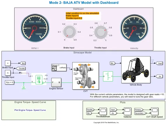 Fig.-9
The study is based on 'Baja ATV with dashboard' as shown in the Model-2 Fig.-9 above, where the input data like throttle and brake input are given from the dashboard instead of inputted with the help of a signal builder. The Fig.-9 (Model 2) shows 'Baja ATV with dashboard' model which consists of throttle meter and brake input in the dashboard instead of giving input through signal builder. Here we used two custom guage and two knob for brake and throttle from the dashboard library. Rest of the blocks and subsystems are common in the above baja ATV model without dashboard. The main concept of using dashboard is study the result by varying the input of brake and throttle, which shows that the velocity and speed of the engine. The gear ratio is maintained as 2.3 for 5 secs and linearly decreases to 1.8 and maintained constant for overall simulation as shown in figure 5. As the brake input varies from 0 - 0.5, the velocity and speed decreases accordingly. As we know that as throttle increases then the power increases by excess input of fuel into the system and shows in the output also increasing and vice versa.
The main intention behind the usage of the dashboard is to study the output value with the variation in the inputted values of throttle and brake, which will give the value of rpm and velocity of the engine in a guage reading.
Result for CASE 2
Here for this model throttle and break is given by using the knob given in the dashboard during the runtime and the value of the throttle and break input can be varied and following result were observed on the plot as given in Fig.-10 and Fig.-11.
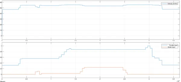
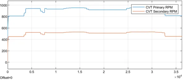 Fig.-10 Fig.-11
The speed varies as per the throttle and brake input. The secondary rpm follows the primary rpm linearly. Here, even if data for some values of velocity might be unavailable, the CVT ratio is still defined.
Here we can note that increasing the brake input decreases the speed and increasing the throttle increases the speed and vice versa.
CASE 3. BAJA ATV with CVT with Lookup Table
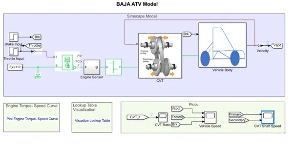 Fig.-12
This model uses a lookup table inside the CVT subsystem which decides the gear ratio according to the velocity fed back to the subsystem.
By using simulink model of CVT consists of step time, generic engine, motion sensors, vehicle transmission, vehicle body,tyres and solver configuration blocks etc., as shown in figure-7. The CVT subsystem includes look up table, Transmission block, input and output shaft inertia and motion sensors as shown in figure-8. The vehicle body subsystem includes vehicle body block, double drum brake and tyres as shown in figure-9. The initial engine speed is given as 2100 rpm, mechanical rotation for driven pulley and driver pulley as 0.8 & 0.7 respectively. The mass of the vehicle as 250kg and 2 axles which connects 4 wheel accordingly.
A lookup table is an array of data that maps input values to output values, thereby approximating a mathematical function. Given a set of input values, a lookup operation retrieves the corresponding output values from the table. If the lookup table does not explicitly define the input values, simulink can estimate an output value using interpolation, extrapolation, or rounding, where:
- An interpolation is a process for estimating values that lie between known data points.
- An extrapolation is a process for estimating values that lie beyond the range of known data points.
- A rounding is a process for approximating a value by altering its digits according to a known rule.
The brake input and throttle input is given by step time, which depends on the run time and varies accordingly. By using Lookup table for gear ratio which takes as input to the CVT and works according to the input gear ratio and obtained the output. This method is very effective which can avoid the unusual torque at the certain speed and very easy to achieve greater velocity & engine speed. It works as closed loop when the input is given by lookup table. The simulink get the input value from lookup table and obtain the result according to the input values of gear ratio. The gear ratio varies from 2.3 to 1.8 as taken as input and output interms of velocity. The maximum velocity reached as 57 kmph approximately.
Result for CASE 3
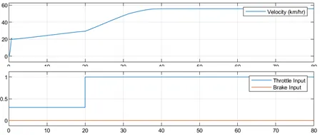
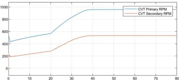 Fig.-13 Fig.-14
In the above figure, the brake is maintained as constant and increase in throttle which shows increase in velocity. The flow of fuel is increses when the throttle increases from 0.3 to 1, thus the power in the engine increases. The torque reaches approximately 7N-m at 1.8 gear ratio, which defines that gear ratio is directly proportional to the torque. By this gear ratio, the speed & velocity can achieve maximum. The gear ratio is assigned in lookup table and given as input to the simulink which reads every input value and obtain the result according to the input.
In the above figure, the primary shaft speed increases by increasing throttle and decreasing by increasing brake input value, which defines that the throttle can flow more amount of fuel which increases the power of the engine and similar to the secondary shaft. The radius of the primary shaft as more than the secondary shaft, the speed is directly proportional to the radius of the shaft. As the radius increases the speed of the shaft also increases.
CONCLUSION:
- As the throttle increases, the power input in the form of fuel to the engine increases and this, in turn, increases the rpm i.e. velocity of the shaft.
- The output speed i.e. the secondary rpm depends on brake (inversely proportional), throttle (directly proportional) and CVT Ratio (inversely proportional) at that instant.
- Lookup tables can extrapolate and interpolate the missing data points of the curve.
- Dashboard elements can take instantaneous input to provide instantaneous output.