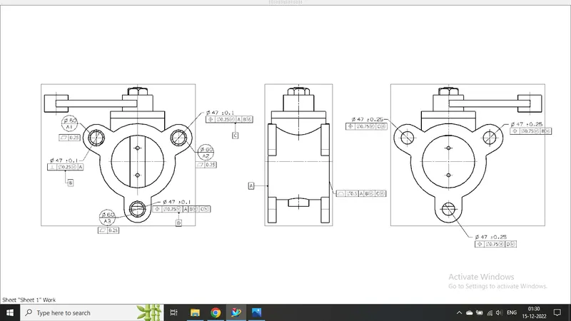
Week 14 challenge
Assemble and apply GD&T to the butterfly valve assembly drawing
Creating assembly file
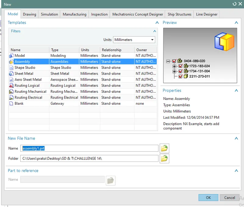
- Go to new file
- Select on assembly
- select folder where you want to save the file.
- Then add all the components needed in assembly using Add component icon in assembly tool.
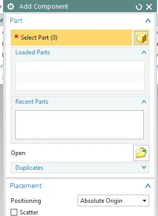
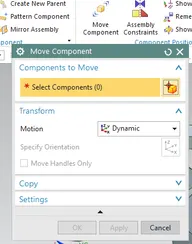
Positioning of the components :
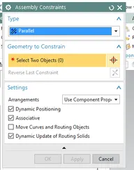
- Use Move component and Assembly Constraints command to move and position the components at the right place.
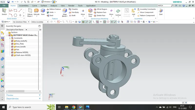
After assembly, Butterfly valve will look like this.
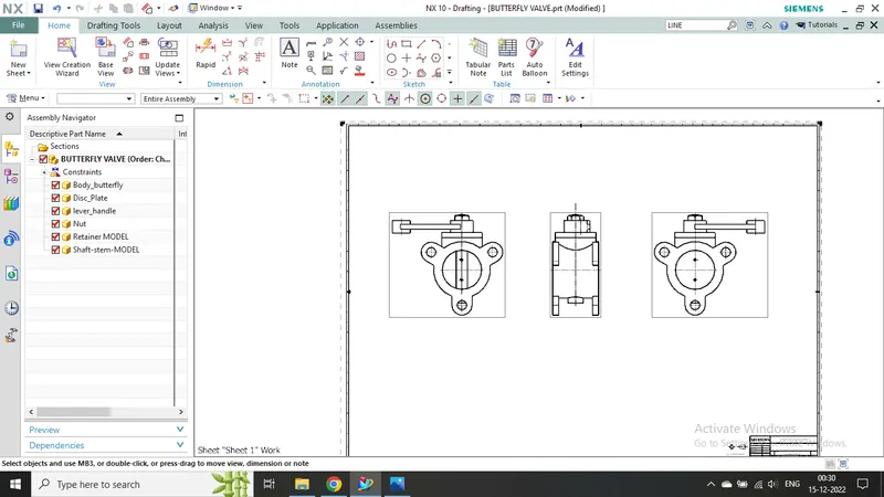
Drawing and dimensioning of the assembly.
Creating Drawing of Butterfly Valve :-
- Go to "Drafting" workbench available in Application tool
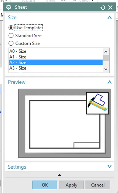
- Select sheet size as A0, Scale - 1:2
- Create Base View, then create other projection view.
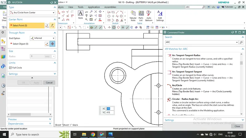
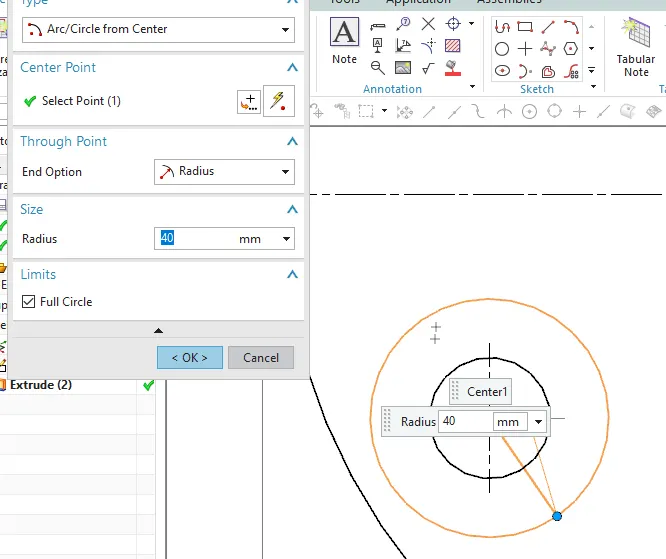
- To create Datum target for circular area, first create circle using "Arc Circle" command.
- Create 2 circles on the drawing sheet, one of same size as hole and another of Diameter 30 mm.
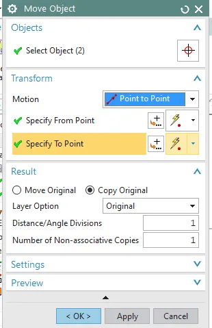
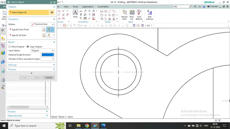
- Create a copy of both circles and move both to the drawing of another hole using "Move Object" command.
- We can get access to move object command by pressing Ctrl+T button on keyboard.
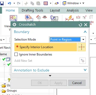
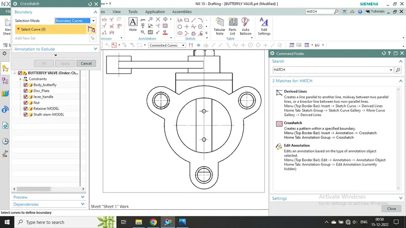
Creat Hatch using "Cross Hatch" command.
Dimensioning and giving tolerance to the Drawing
- Do dimensioning using "Rapid Dimensioning" command.
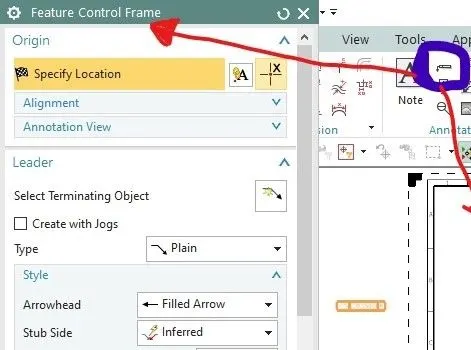
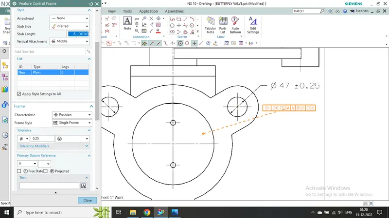
- Create feature control frame by using "Feature Control Frame" command. Apply different tolerance method accordingly.
- Datum feature Symbol is used to define general datum.
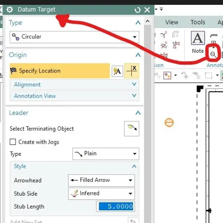
- Use Datum Target command for hatchsd area.
- All the commands are shown in the image below.
Final Drawing with Dimension and neccessary tolerance provided.