Wiring harness design in CATIA V5 - 3D modeling Week 7 Challenge
Q1. Flatten the harness assembly completed in “ week 4 challenge”. Place the flattened view on drawing sheet. Ensure bundles with protective coverings has different visuals on drawing view.
DT06-2S
Now changing the mwchanical part into electrical part design.
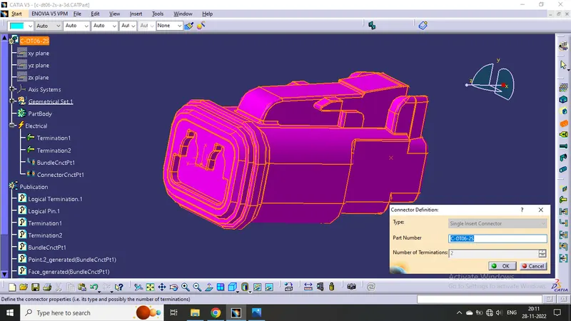
Defined the middle point with help of the mid point. On the connector side and bundle side.
Then define Bundle connection point
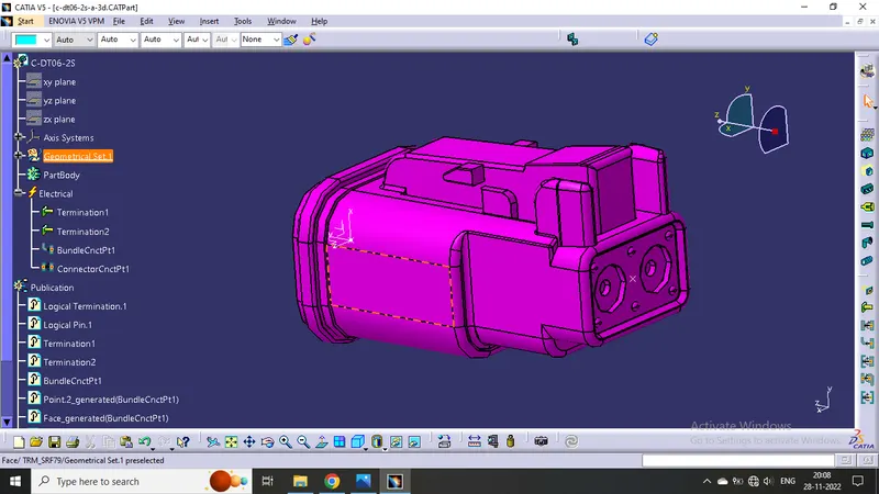
Given axis system to connector side.
Rotated x-axis 90 degrees for y-axis coincidence
Then define connector connection point
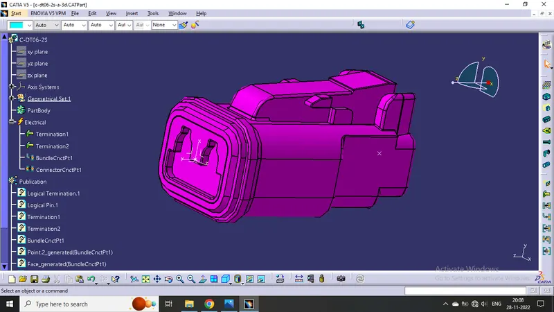
.
DT06-4S
Do same as above connector
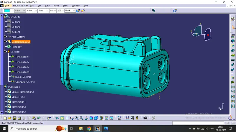
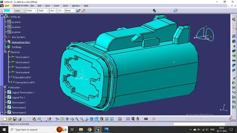
DT06-6S
First imported models from given link. open mechanical part design.
Then do same
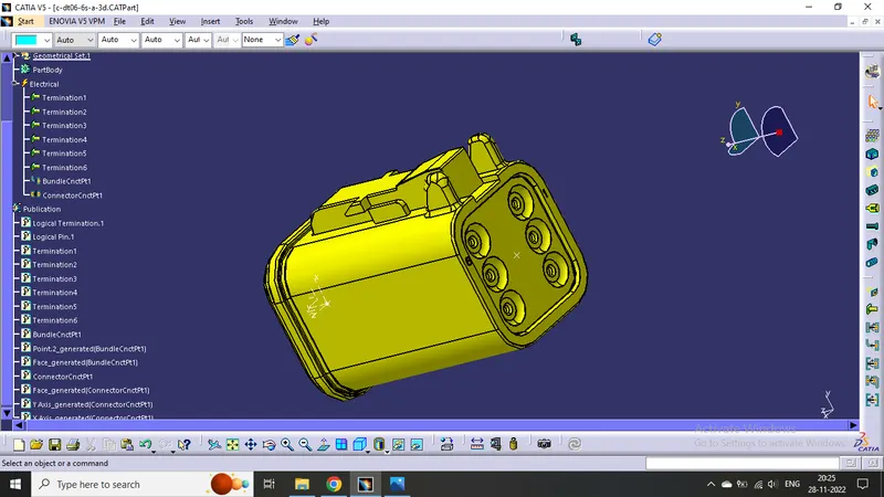
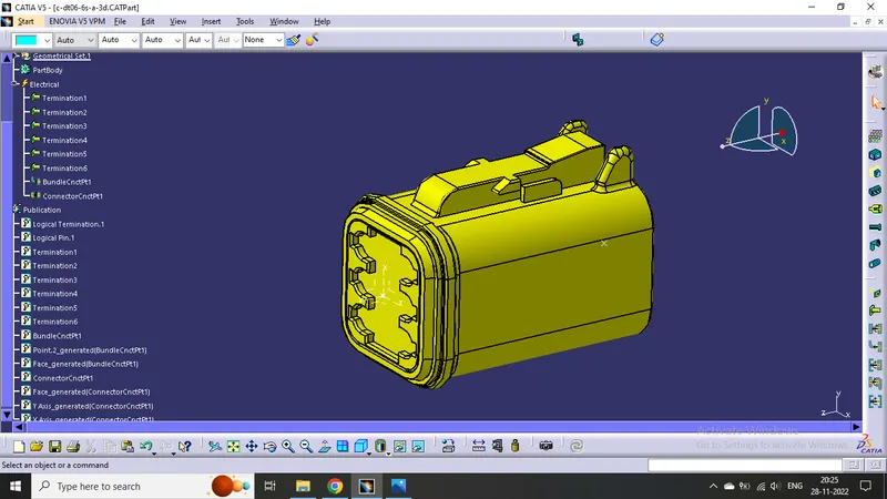
DT06-08SA
Now changing the workbench electrical part design.
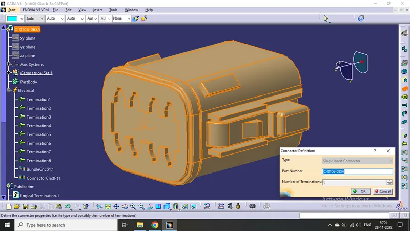
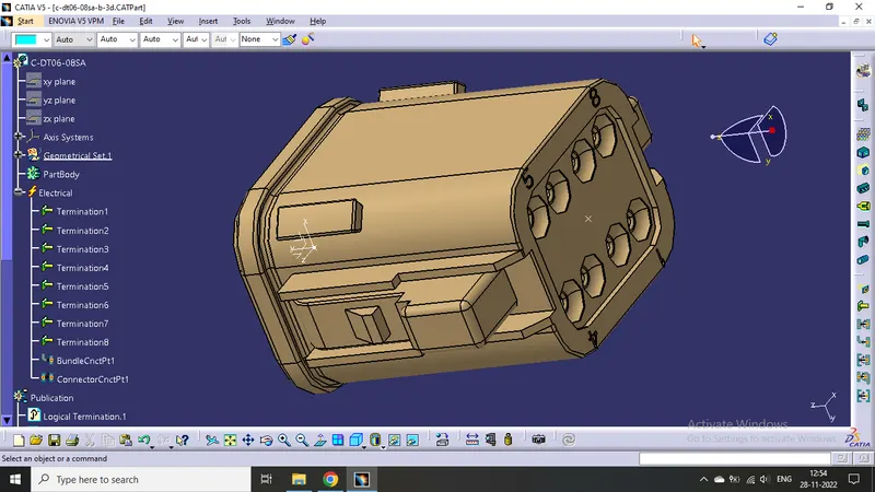
Then Defined the connector side as the connector connection point.
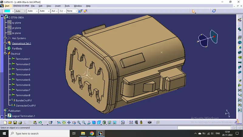
Defined bundle connection side as a bundle connection point.
Product
Draw a sketch according to the question
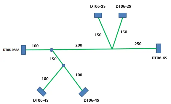
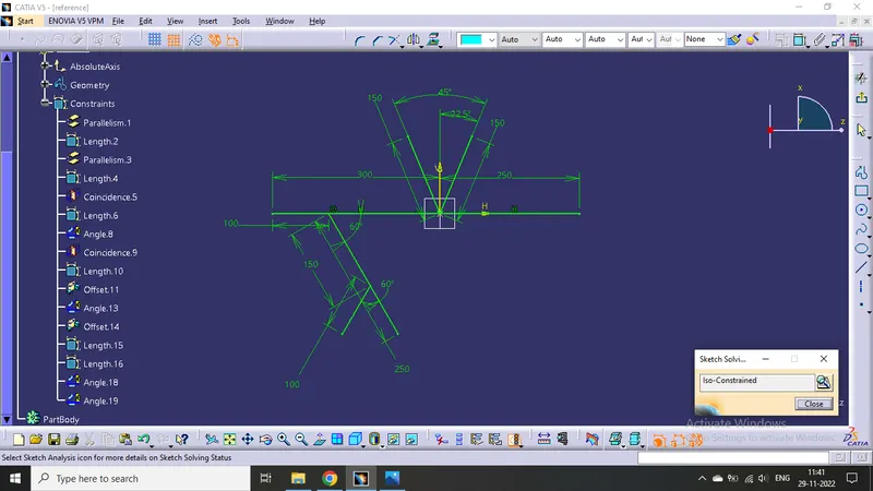
- Open a new product file and import all the defined models and the reference sketch into it.
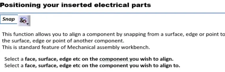
- Then place all the connectors on the right position using snap tool
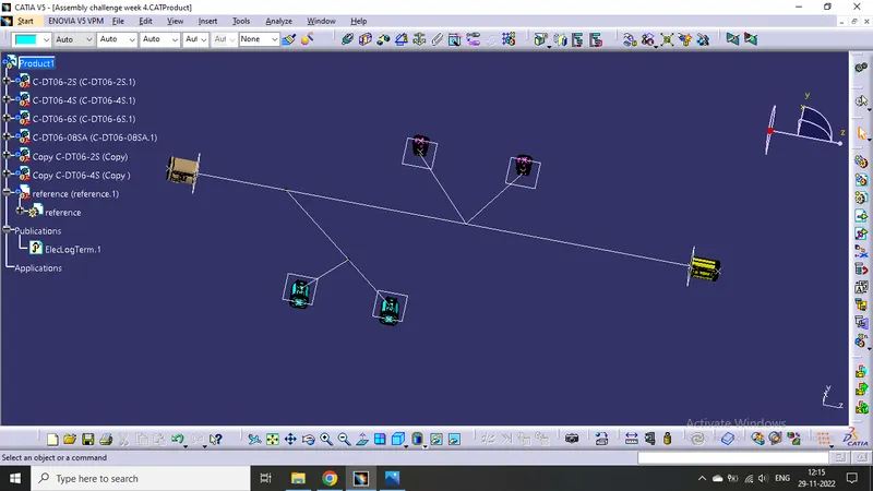
- Click on geometrical bundle command available in electrical harness assembly to convert mechanical assembly into electrical assembly.
- Then click on "Multi Branchable Document" to go on the branchable workbench.
- Then click on "Branch definition" to male branches.
- Then make Branch point click on "Add Branch Point".
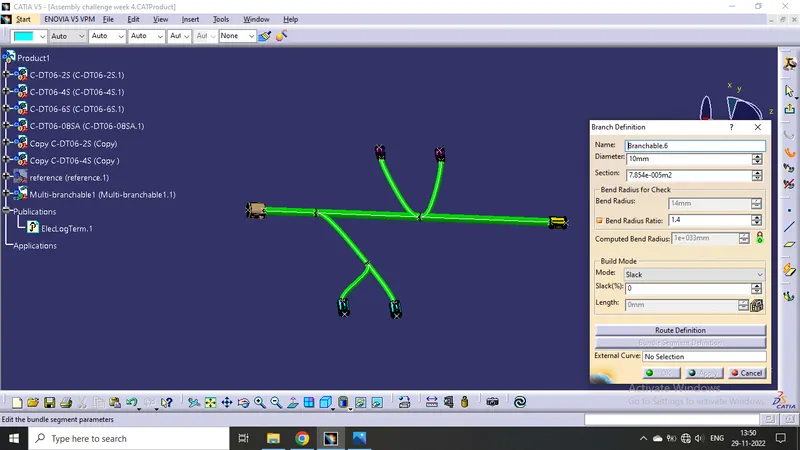
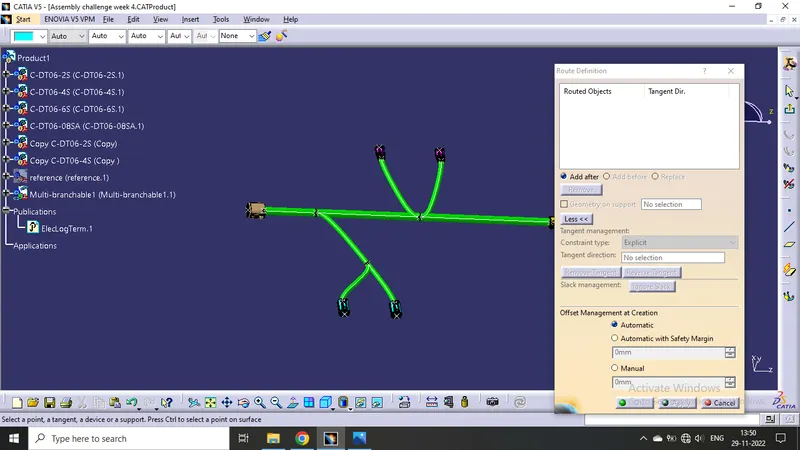
Now the branches has been made.
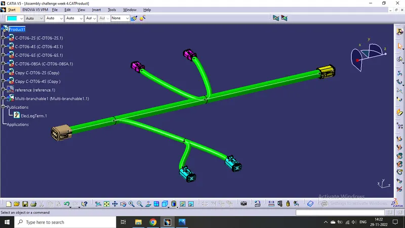
Adding protective covering on all branches connected to DT06-2S & DT06-4S connectors.
- Click on "Protective Covering" command in electrical harness assembly workbench.
- select the branch to be protected.
- click on catalogue icon then click on the protective cover which we want to use.
- Then click OK.
- We can change extrimity positions by double clicking on the same.
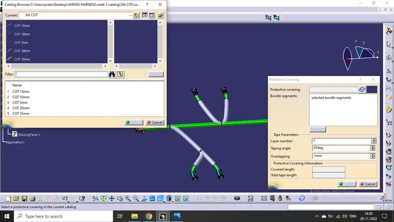
Made Cot for all sub-branches by maintaining a 30mm distance from the connector side.
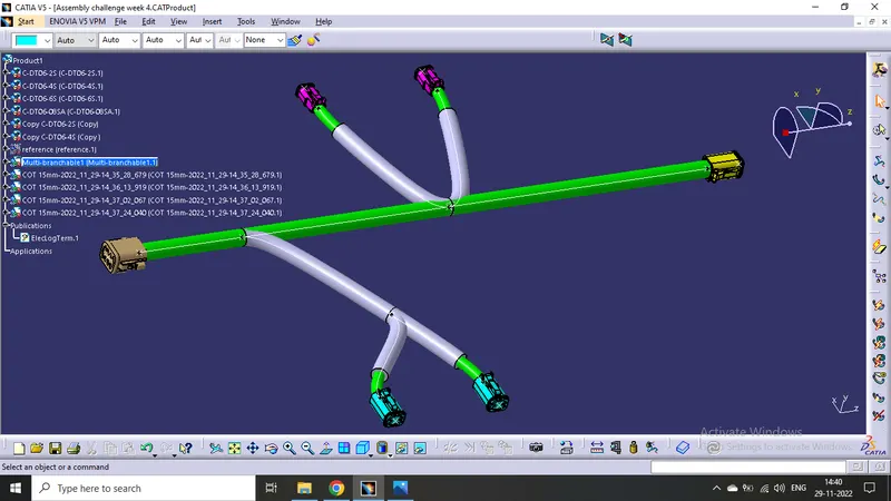
For flattening the harness bundles :
- Go to the "Electrical Harness Flattening" workbench.
- Click on the "Harness Flattening Parameter" available in the workbench.
- Then adjust the parameters accordingly.
- Save the file in the same location where the harness is located whose flattening has to be done.
- Then Extract the harness product file into the flattness product file by clicking "Extract " command in the flattening workbench.
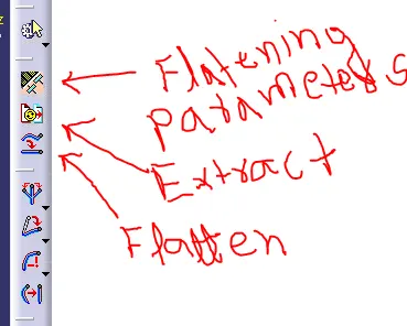
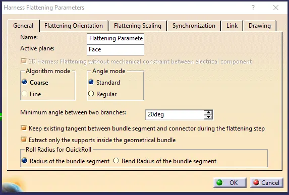
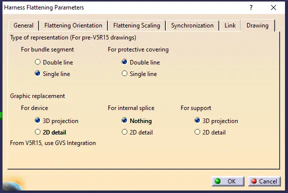
Then use the "Flatten " command.
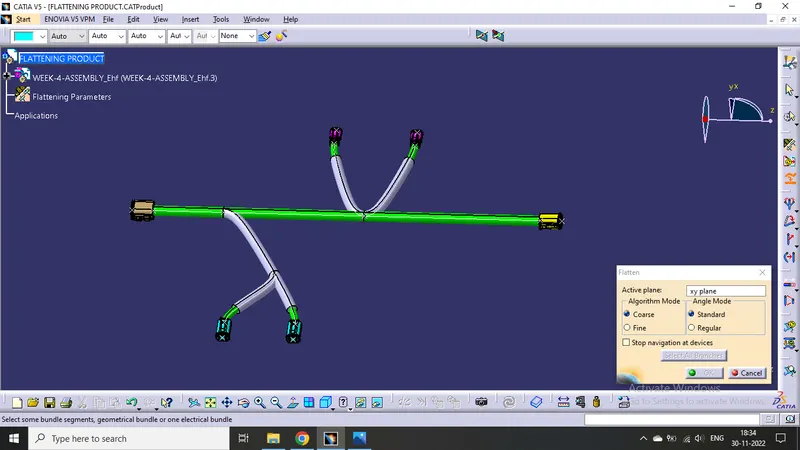
Then we will get the following structure :
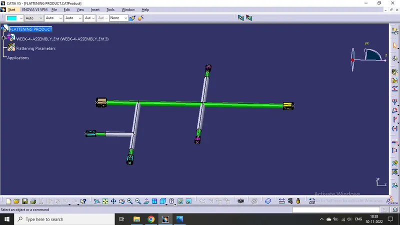
By adjusting the bundles with the following comands availabe in the same workbench :
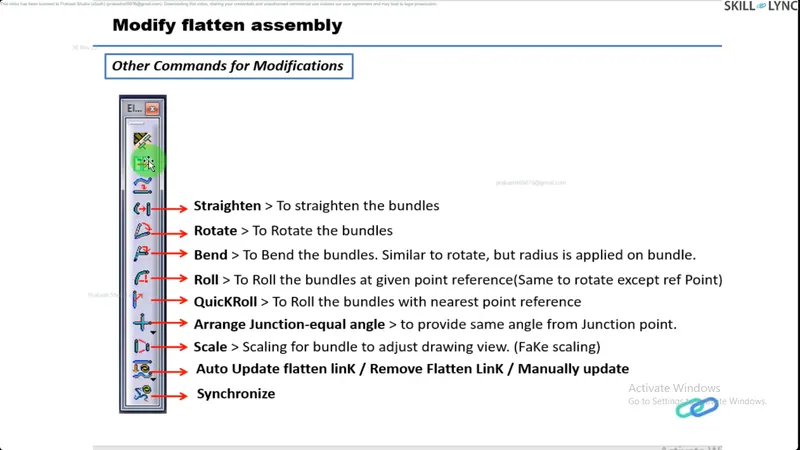
We will get the below harness arrangement :
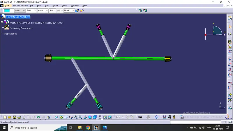
Ensure bundles with protective coverings has different visuals on drawing view.
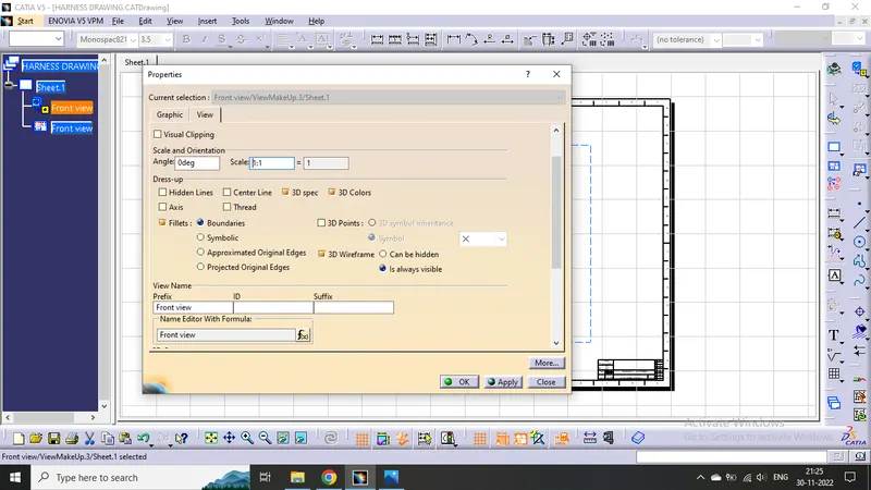
Create new Drawing file and after adjusting the properties like below
We will get the required view of the harness bundle assembly :
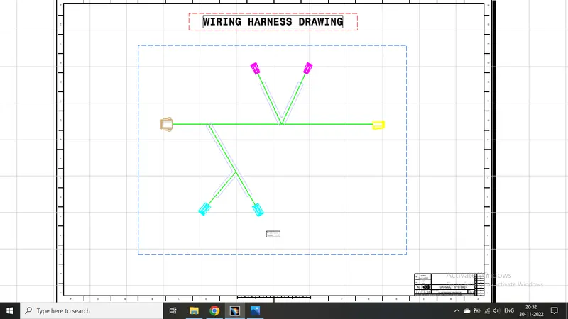
Challenge completed.