Project 1
Q. Route the Wiring harness on Given Engine and Prepare flatten view drawing in CATIA V5. Application of all Packaging rules, Industry best practices studied in this course shall be demonstrated in design. Apply Protection coverings as required.
Available connector 3D data can be used, or you can download the connectors from www.te.com
Prepare & Submit all necessary reports like clearance, Clipping/Clamping selection, Harness fixing requirements, Harness continuity, Assumptions if any along with CATIA 3D data.
Engine cad data to be downloaded from www.grabcad.com
Now changing the mwchanical part into electrical part design.
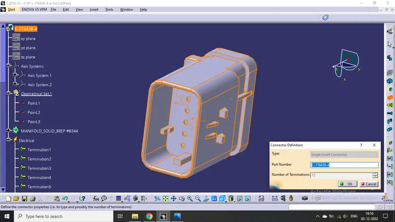
Defined the middle point with help of the mid point. On the connector side and bundle side.
Then define Bundle connection point
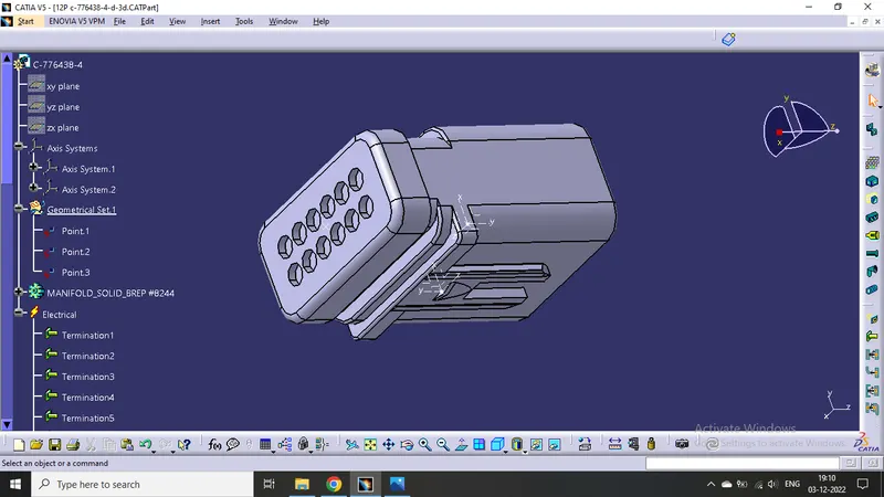
Given axis system to connector side.
Rotated x-axis 90 degrees for y-axis coincidence
Then define connector connection point
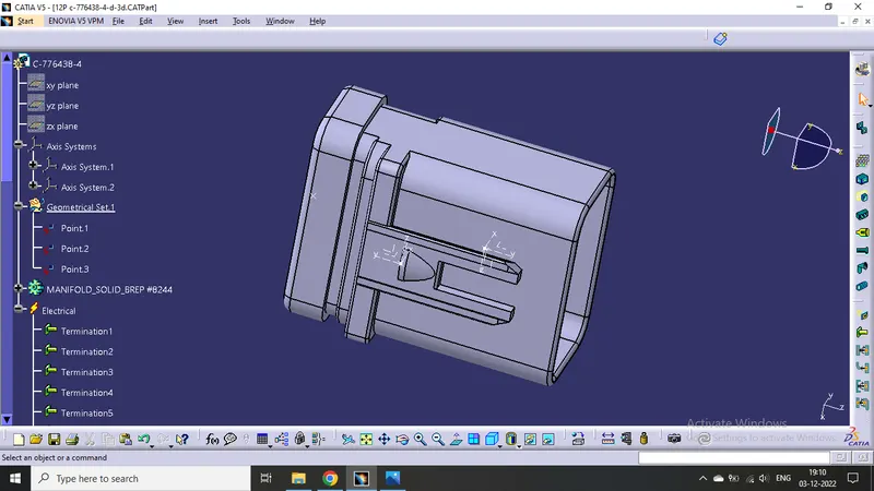
Do same as above connector
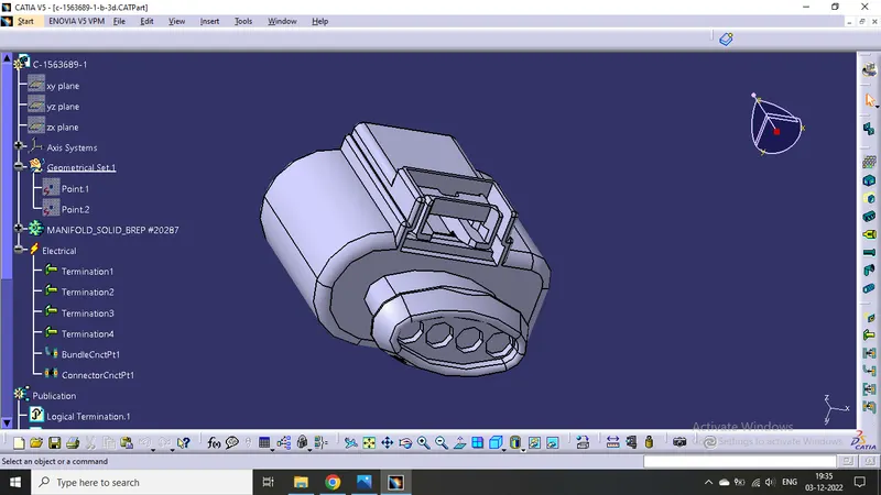
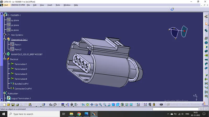
Then do same
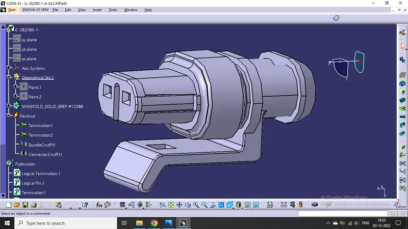
ANTI ROTATIONAL CAVITY CLIP
- Define it as mounting equipment.
- Define cavity
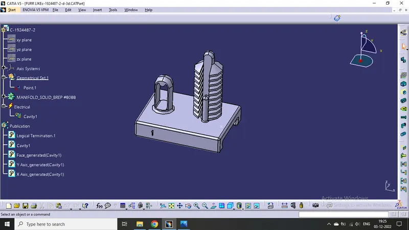
Bottom Channel for Routing Harness :
- Define it as equipment.
- Define 9 bundle connection points.
- This is left hand side channel, Therefore also create one more channel for Right hand side by using "Symmetry" command in the assembly workbench.
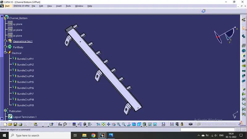
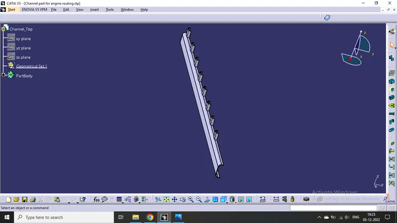
Top Channel for Routing Harness :
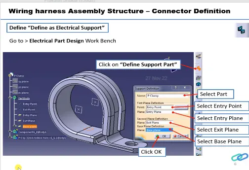
P clamp for support :
Define it as support
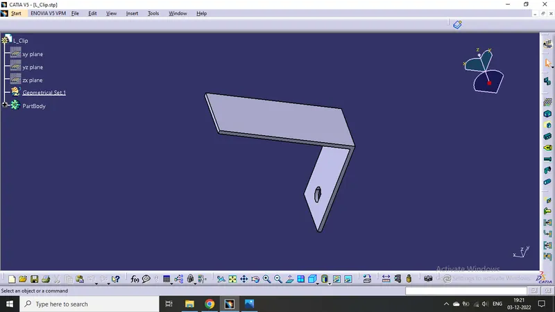
L clamp for support :
No need to define as support as it is an external, not provided with harness bundle.
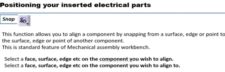
Positioning :
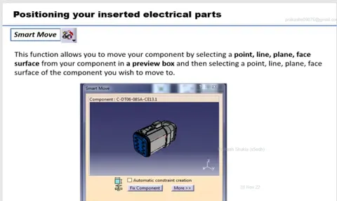
Positioning of all the parts is done by the help of "Smart move" command and "Compas".
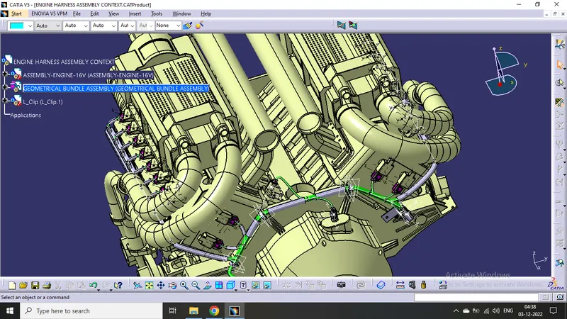
Creating Geometrical Bundle :
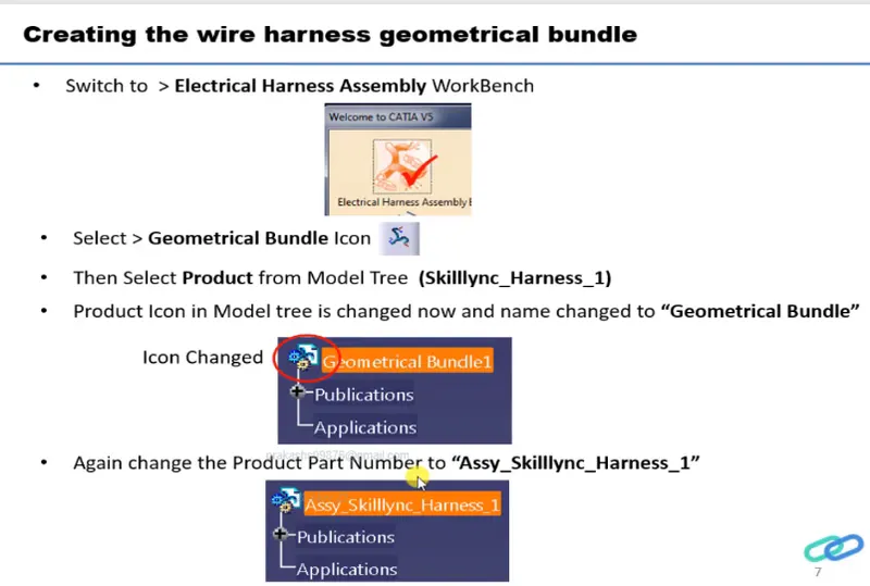
- Click on geometrical bundle command available in electrical harness assembly to convert mechanical assembly into electrical assembly.
- Then click on "Multi Branchable Document" to go on the branchable workbench.
- Then click on "Branch definition" to male branches.
- Then make Branch point click on "Add Branch Point".
- Create branches as per need.
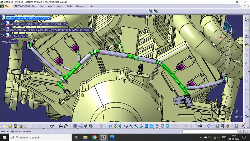
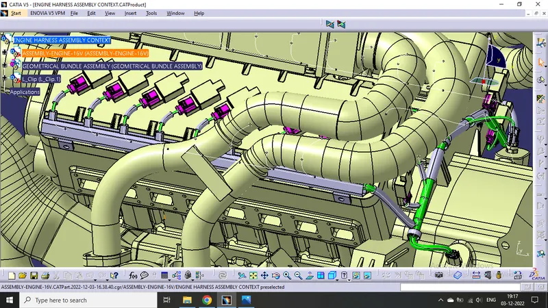
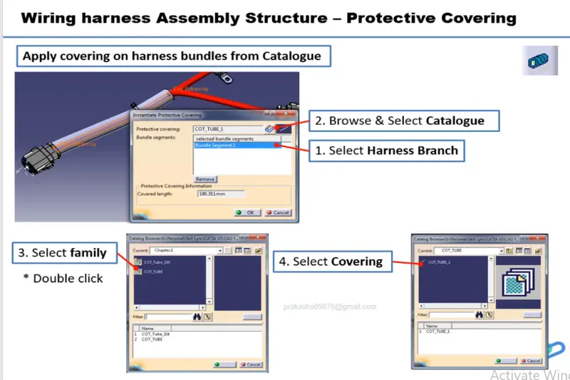
Adding protective covering on all branches connected to DT06-2S & DT06-4S connectors.
- Click on "Protective Covering" command in electrical harness assembly workbench.
- select the branch to be protected.
- click on catalogue icon then click on the protective cover which we want to use.
- Then click OK.
- We can change extrimity positions by double clicking on the same.
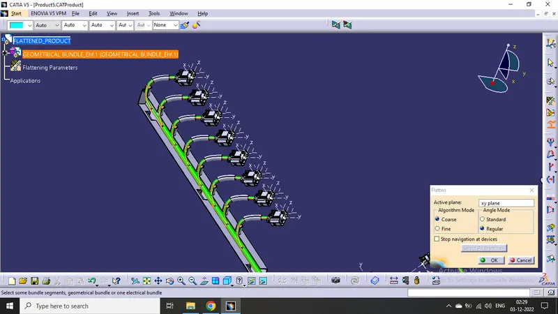
For flattening the harness bundles :
- Go to the "Electrical Harness Flattening" workbench.
- Click on the "Harness Flattening Parameter" available in the workbench.
- Then adjust the parameters accordingly.
- Save the file in the same location where the harness is located whose flattening has to be done.
- Then Extract the harness product file into the flattness product file by clicking "Extract " command in the flattening workbench.
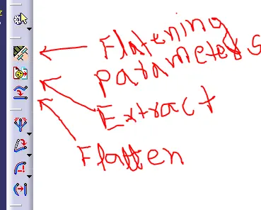
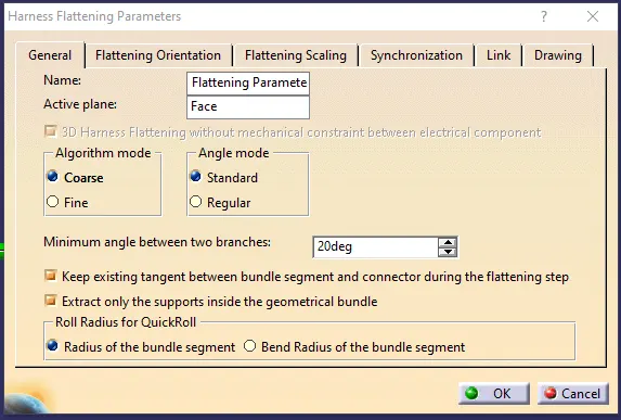
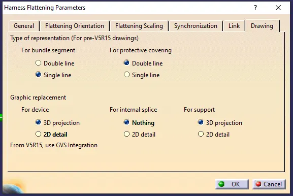
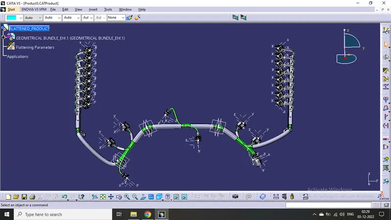
Then use the "Flatten " command.
Then we will get the following structure :
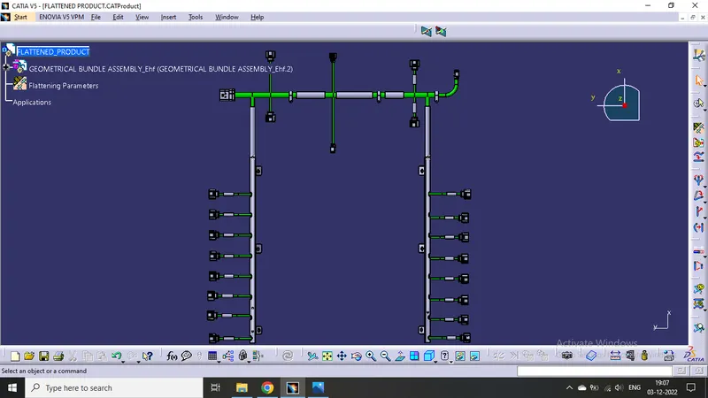
By adjusting the bundles with the following comands availabe in the same workbench :
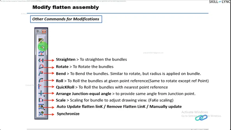
Creating Harness Bundle Drawing :
Ensure bundles with protective coverings has different visuals on drawing view.
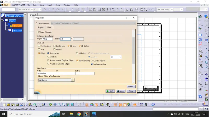
Create new Drawing file and after adjusting the properties like below
We will get the required view of the harness bundle assembly :
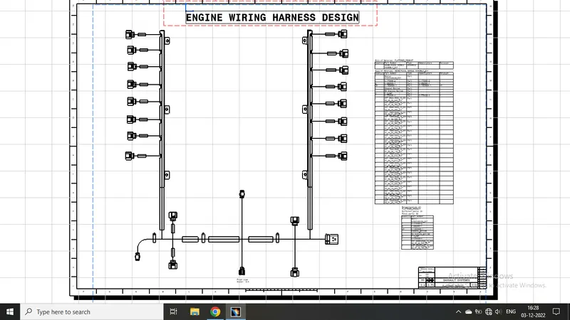
Challenge completed.