Wiring harness design in CATIA V5 - 3D modeling Week 5 & 6 Challenge
Q1. Route the following harness layout in Electrical workbench. Make assumption for harness bundle diameters. Use the connectors provided. After completion of routing,
- Check the bundle Continuity. Add snap of result in submission
- Add annotation to all connectors. Make an assumptions for annotations like connect 1 , 2 etc
- Check for the bundle warning. Add snap.
- Generate CAT.part of harness assembly and convert is in. igs format.
CONNECTOR 1
First imported models from given link. open mechanical part design.
Now changing the mechanical part into electrical part design.
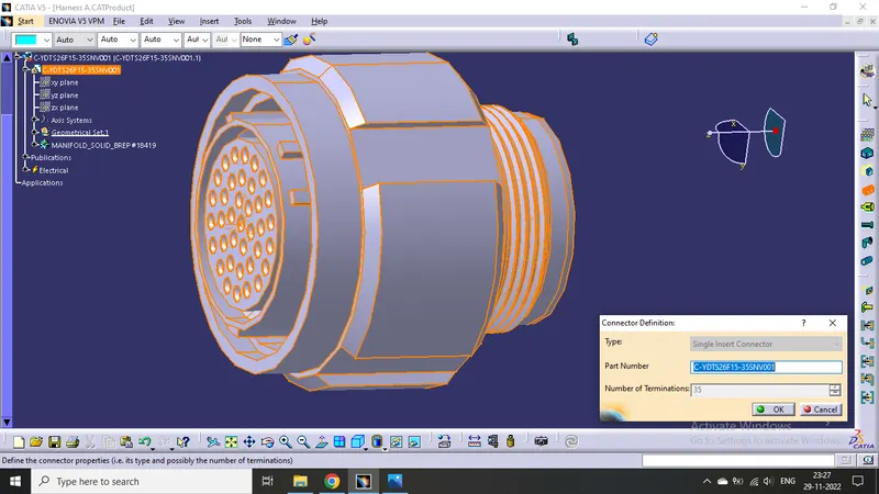
Defined the middle point with help of the mid point. On the connector side and bundle side.
Then define Bundle connection point
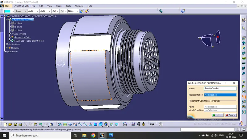
Given axis system to connector side.
Rotated x-axis 90 degrees for y-axis coincidence
Then define connector connection point
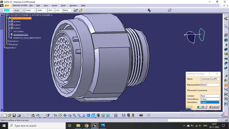
CONNECTOR 2
First imported models from given link. open mechanical part design.
Now changing the mechanical part into electrical part design.
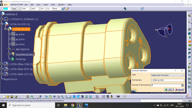
Defined the middle point with help of the mid point. On the connector side and bundle side.
Then define Bundle connection point
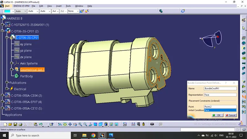
Given axis system to connector side.
Rotated x-axis 90 degrees for y-axis coincidence
Then define connector connection point
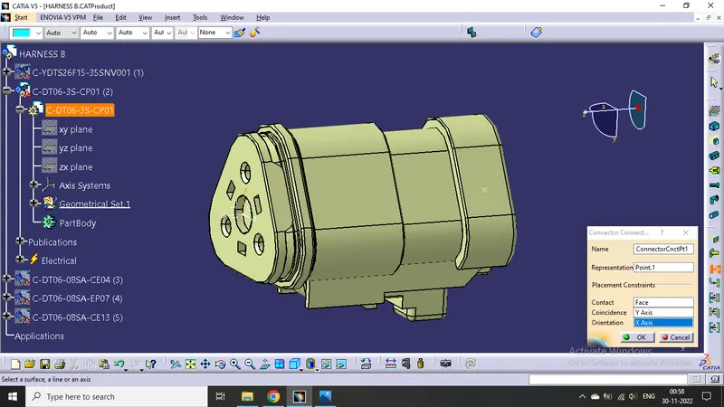
CONNECTOR 3
Do same as above connector
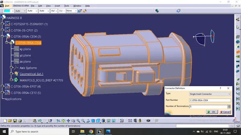
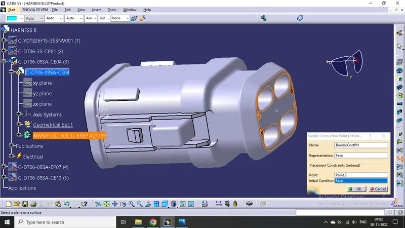
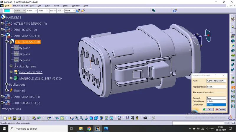
CONNECTOR 4
It is same as connector 9.
Now changing the workbench electrical part design.
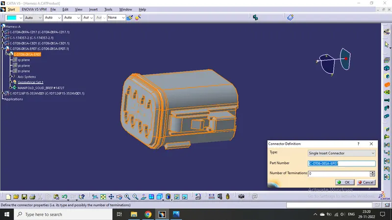
CONNECTOR 5
Do same as above connector
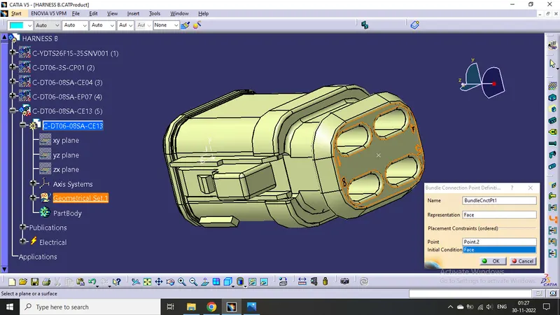
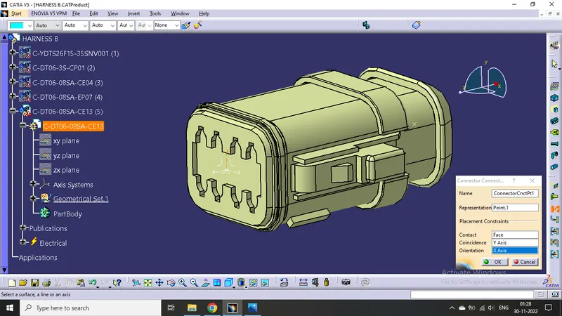
CONNECTOR 6
Do same as above connector
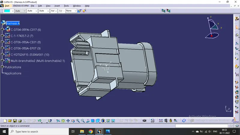
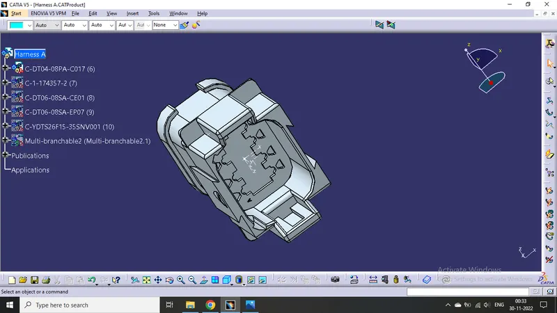
CONNECTOR 7
Do same as above connector
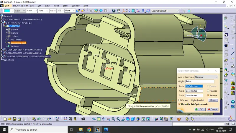
CONNECTOR 8
Now changing the mechanical part into electrical part design.
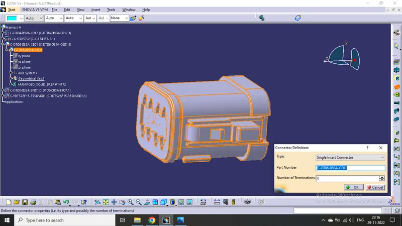
Defined the middle point with help of the mid point. On the connector side and bundle side.
Then define Bundle connection point
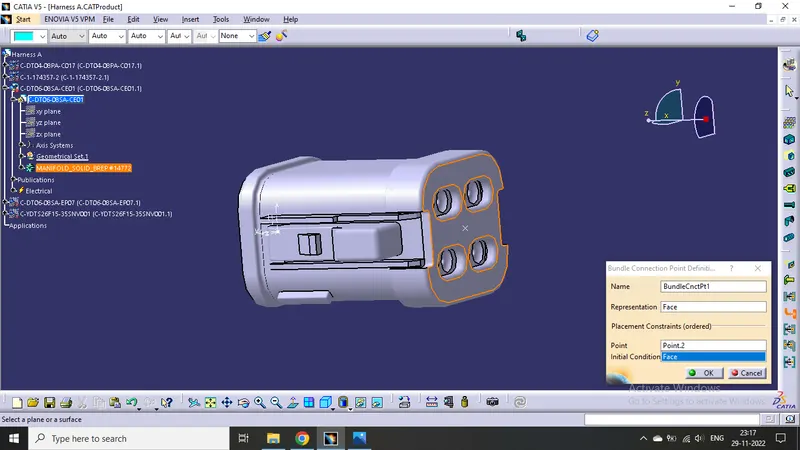
Given axis system to connector side.
Rotated x-axis 90 degrees for y-axis coincidence
Then define connector connection point
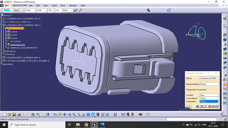
CONNECTOR 9
Now changing the workbench electrical part design.
Then Defined the connector side as the connector connection point.
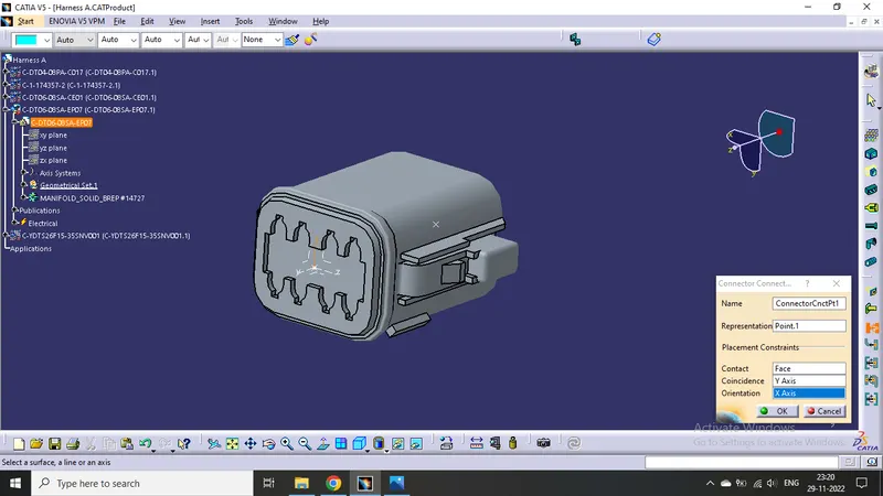
Defined bundle connection side as a bundle connection point.
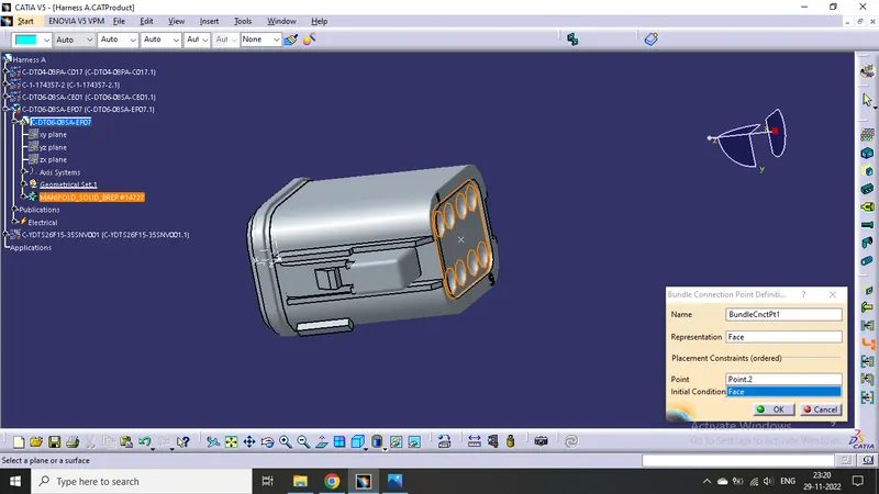
CONNECTOR 10
First imported models from given link. open mechanical part design.
Then do same
Product
Draw a sketch according to the question
HARNESS A MAKING :
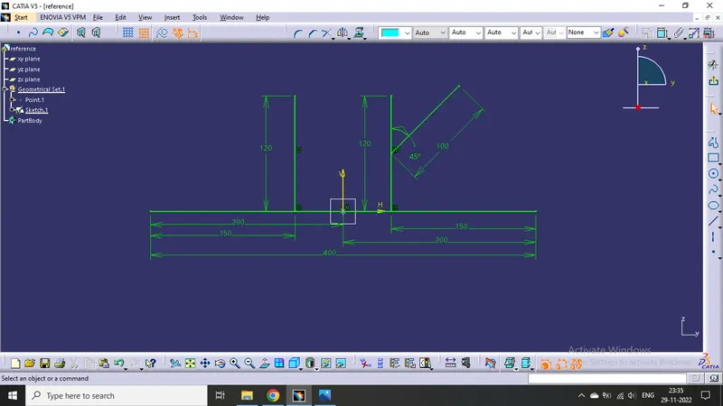
- Open a new product file and import all the defined models and the reference sketch into it.
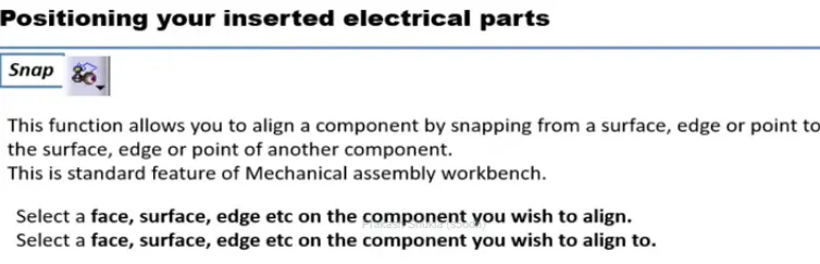
- Then place all the connectors on the right position using snap tool
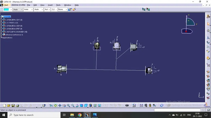
- Click on geometrical bundle command available in electrical harness assembly to convert mechanical assembly into electrical assembly.
- Then click on "Multi Branchable Document" to go on the branchable workbench.
- Then click on "Branch definition" to male branches.
- Then make Branch point click on "Add Branch Point".
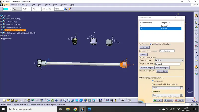
Error shown by red line
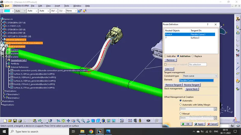
Adjusted the tangency from the point on main bundle to the plane normal to main branch, then the error has been resolved
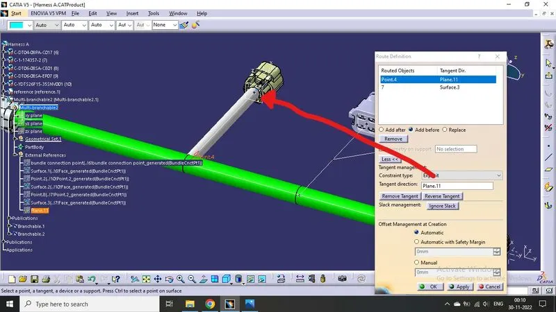
Now the branches has been made.
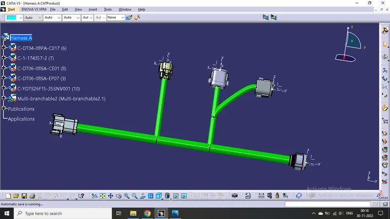
DO SAME FOR HARNESS B MAKING :
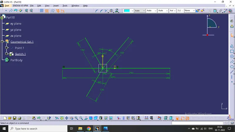
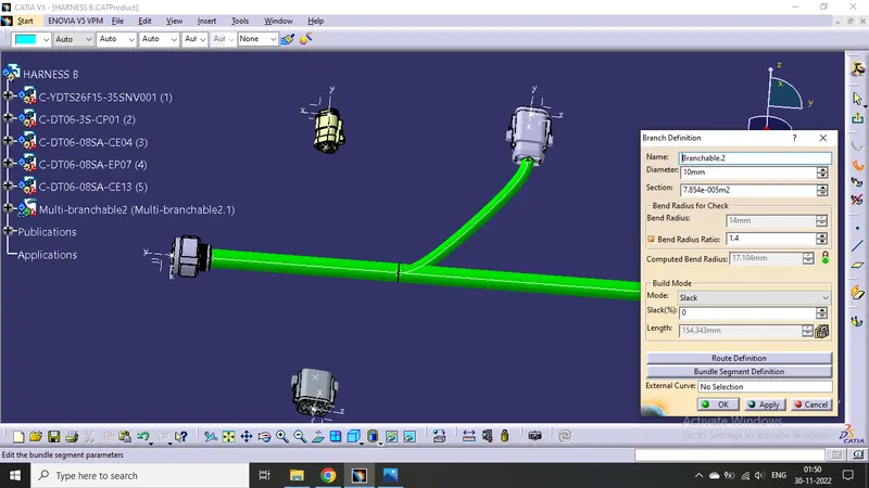
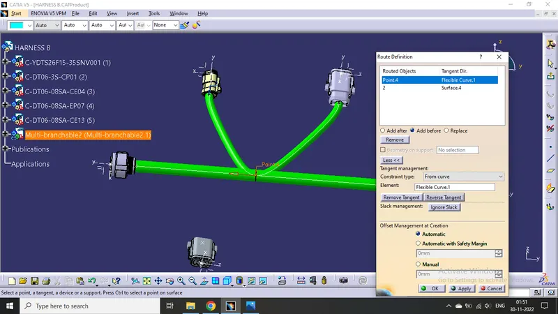
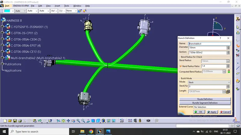
INTERCONNECTION OF BOTH HARNESS A AND HARNESS B
Do it by "Connect Electrical Devices" command present in electrical assembly workbench.
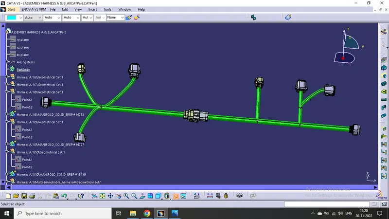
Add annotation to all connectors. Make an assumptions for annotations like connect 1 , 2 etc.
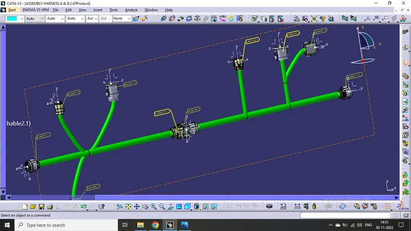
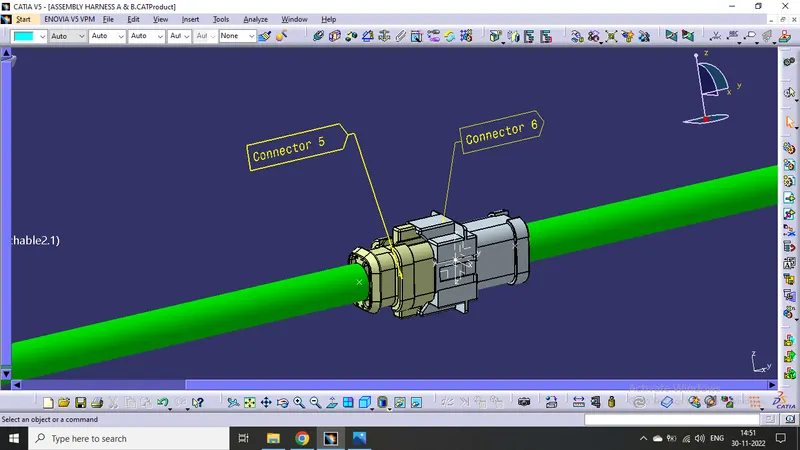
Check the bundle Continuity. Add snap of result in submission :
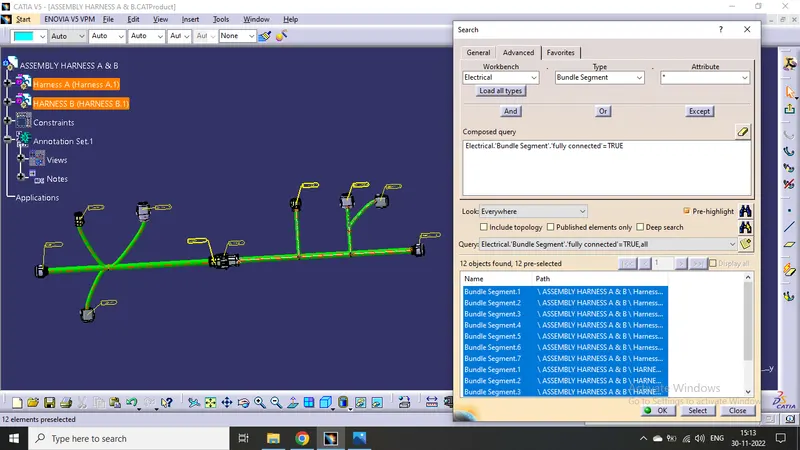
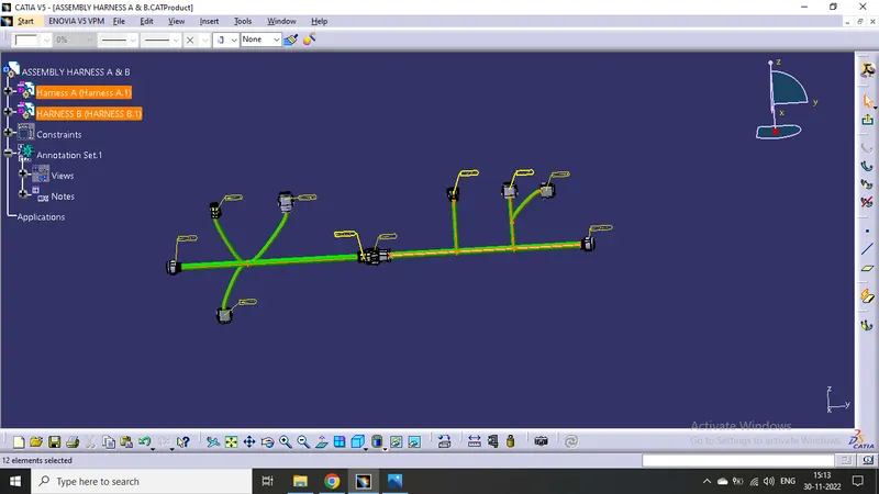
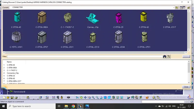
Stored the connectors in the Catalogue.
Challenge completed.