Structural Analysis of Jet Engine Blade Using MATLAB.
Title :- "Structural Analysis of Jet Engine Blade".
Aim :- To generate a code for structural analysis of Jet Engine Blade and plot results of overall analysis.
Objective :-
1. Generate a code for structural Analysis.
2. Import the Blade geometry.
3. Generate an appropriate mesh for geometry.
4. Applying proper boundary conditions.
5. Apply pressure loads upon pressure side as well as on suction side.
6. Plot the results after analysis.
Theory :-
Structural Analysis. :
Structural analysis is process of calculting and determining effects of loads and internal forcess on structure or object. Structural Analysis is generally important for engineers, to ensure that they completely understand the load path and impact of load on that object. It allows to ensure a piece of equipement or structure is safe for use under estimated load, it is expected to withstand. Structural analysis either be done during design , testing. And generally accounts for materials used, geometry of the structure and applied load.
Structural Analysis usually looks at individual structural element, amd the forces they undergo. So it is always important review how each component behave under the load. This is the core focus of the structural analysis.
Methods of structural analysis.
There are various methods used to perform structural analysis, depending upon level of accuracy required. We can define structural analysis as being any of the following method,
1. Hand Calculation :-
Simple hand calculations are extrememly fast and easy way to evaluate the effects of simple forces on simple structures. An example would be calculating the bending movement, forces on horizontal beam. These back envelope calcultions are standard practice in engineering.
2. Finite Element Analysis (FEA)
Finite element analysis is a complex numerical method used to solve complicated problems, which consist no of variables inputs such as boundary conditions, applied load and support time. It is far more complicated, yet more accurate method to run structural analysis compared to hand calculations. FEA requires that the component brokes into no of smaller part, which can be evaluated individually for accurate solution. It can be extremely difficult and time consuming process to set up and run. But FEA is an extremely accurate and powerful method of structural analysis and is the backbone of the most structural analysis software.
3. Structural Analysis software.
There are greate no of structural analysis software that can perform accurate FEA calculation without the difficulty of having manually set up the complex process. Such analysis software allows users to evaluate the structure with high precision and low calculation time.
Code Explanation :-
%Structural Analysis of Jet Engine Blade.
clear all
close all
clc
%Create a model for structural analysis.
model = createpde('structural','static-solid'); %Defining mode of analysis and type of geometry.
%Import Geometry for analysis.
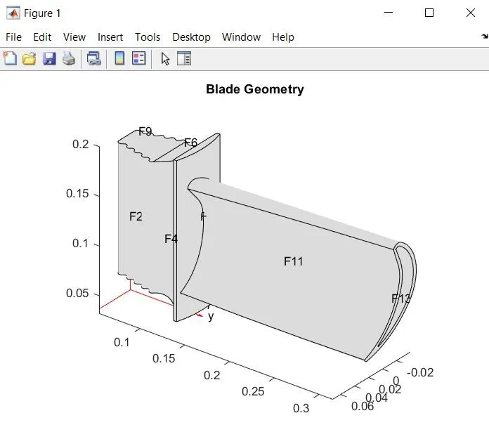
importGeometry(model,'Blade.stl'); %While importing geometry, check for its extension.
figure(1)
pdegplot(model,'Facelabel','on'); %Enable facelabeling.
title('Blade Geometry');
%Generate a mesh for Geometry.
figure(2)
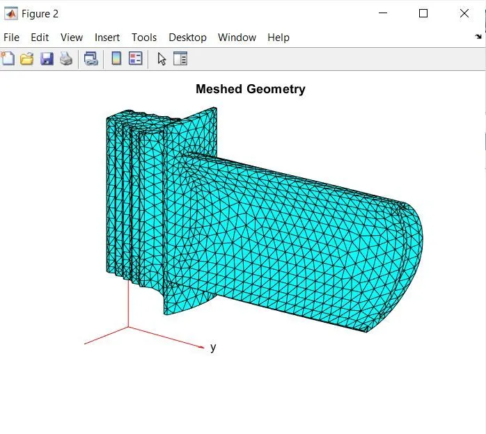
msh = generateMesh(model,'Hmax',0.01); %Max element size kept as 0.01.
pdeplot3D (model);
title('Meshed Geometry');
%Defining Blade material properties.
E = 227e9 % In pascal
nu =0.27 %dimensionless
structuralProperties(model,'YoungsModulus',E,'PoissonsRatio',nu);
%Applying Boundary Conditions.
structuralBC = (model,'Face',3,'Constraint','Fixed');
%Applying Boundary load conditions.
p1 = 5e5 % Load on pressure side.
p2 = 4e5 % Load on suction side.
structuralBoundaryLoad (model,'Face',11,'Pressure',p1);
structuralBoundaryLoad (model,'Face',10,'Pressure',p2);
%Solve the analysis.
result = solve(model);
%Plotting the results of analysis.
figure(3)
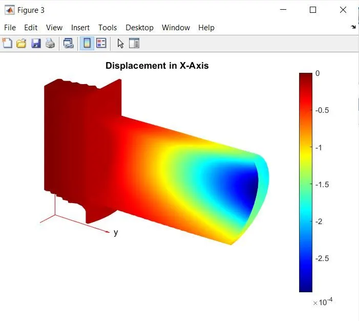
pdeplot3D(model,'ColorMapData',result.Displacement.ux) %Displacement in x-axis.
title('Displacement in X-axis');
figure(4)
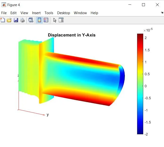
pdeplot3D(model,'ColorMapData',result.Displacement.uy) %Displacement in y-axis.
title('Displacement in Y-axis');
figure(5)
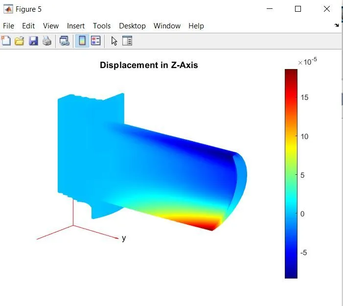
pdeplot3D(model,'ColorMapData',result.Displacement.uz) %Displacement in z-axis.
title('Displacement in Z-axis');
figure(6)
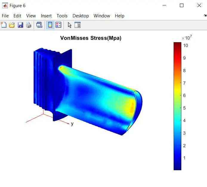
pdeplot3D(model,'ColorMapData',result.VonMisesStress);
title('Von Mises Stress (Mpa)');
Step-1 :- Creating Structural Analysis model using createpde command.
Step-2 :- Next step is to define mode of analysis and type of geometry. In this case mode of analysis is defined as 'structural' and type od geometry as 'Static-Solid'.
Step-3 :- Import the geometry for analysis. But need to check for geometry file extension, it should be .stl.
Step-4 :- Generate a proper mesh on geometry. In this problem Maximum element size kept as 0.01.
Step-6 :- Defining Bounday Conditions using structuralBC command. Apply constraint on respect faces of geometry, in this case face 3 fixed.
Step-7 :- Defining Boundary load conditions using structuralBoundaryLoad command. In this case pressure are applied on Face 11 and Face 10 of blade.
Step-8 :- Solve the model and plot the results for displacement and stress developed on blade.
Results :-
Importing Geometry and label the faces of geometry with numbers, for easy understanding while applying load and boundary conditions on faces.
Meshed Geometry.
Dispacement in X-Axis.
Displacement in Y-Axis.
Displacement in Z-Axis.
Von Mises Stress (Mpa) Developed on blade.