Wiring harness design in CATIA V5 - 3D modeling Week 2 Challenge
Aim :- To Download following connectors & Connector clip cad data from given link & define it as Electrical Connector using Electrical Part design Workbench. Define all the necessary properties to Connectors & Clip.
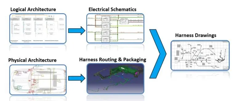
Typical design flow of EDS System.
Defining the connector
We need to define the connector by following the below steps.
- Download the connector data.
- Create required geometrical parameter.
- Define part as electrical connector.
- Define bundle connection point.
- Define connector connection point.
- Define cavity connection point.
Defining the mounting clip
- Download the clip 3d data.
- Create the geometry parameter.
- Define the part as mounting component.
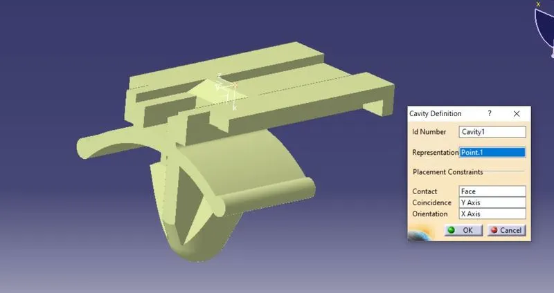
- Define the part as cavity.
Defining the connector is described below
- Downloaded the cad data from the supplier's website and the images are shown below.
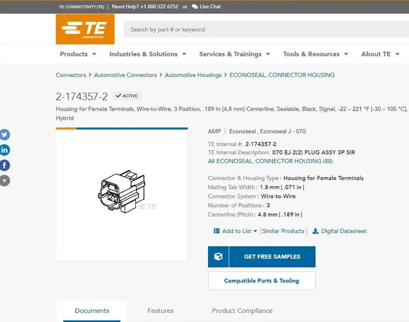
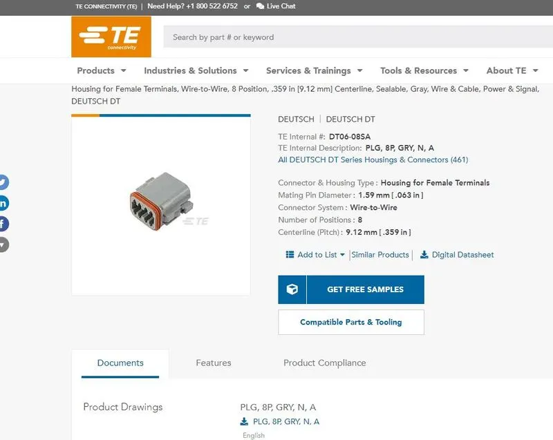
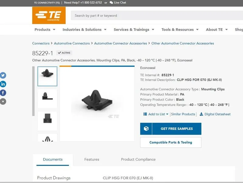
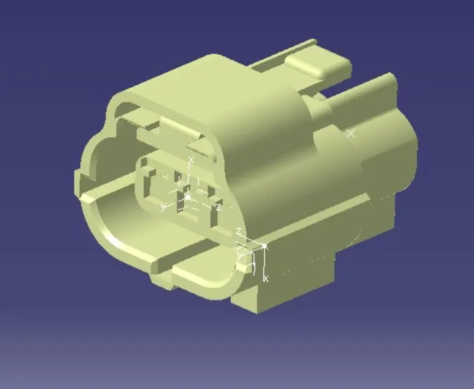
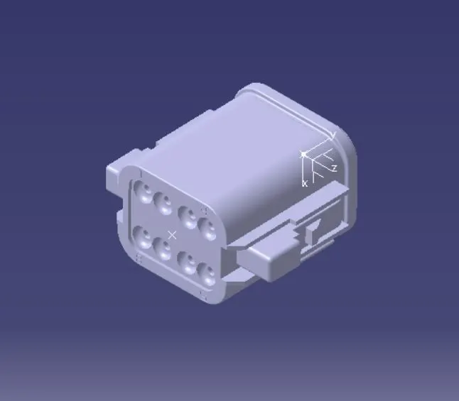
Below Images shows downloaded CAD files.
C-2-174557-2 Connector.
DT-06-08SA Connector.
C0085229-01-03 Mounting Clip.
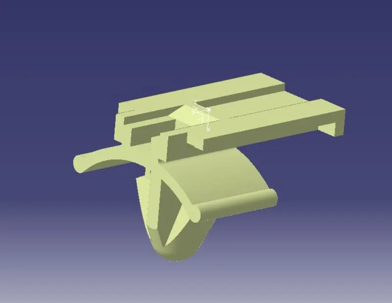
Now we need to defined all the component as an Electrical Component.
1. C-2-174557-2 Connector.
Define Component as Connector.
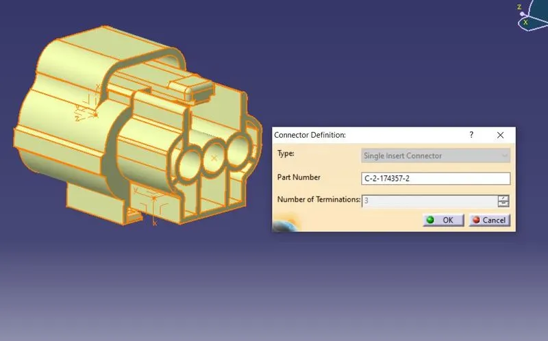
Then Define its Bundle Connection Point.
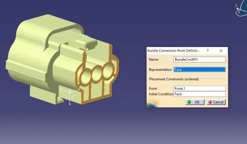
Then Define its Connector Connection Point.
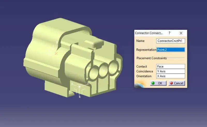
Then Define its Cavity Connection Point where mounting clips need to be fit.
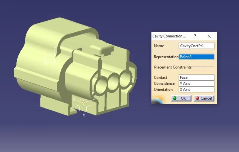
2.DT-06-08SA Connector.
Define component as Electrical Connector.
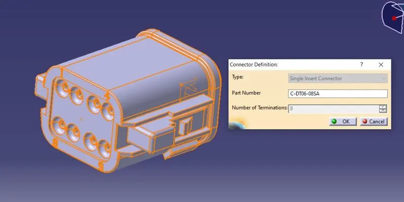
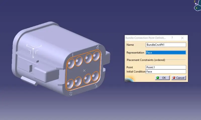
Then Define its Bundle Connection Point.
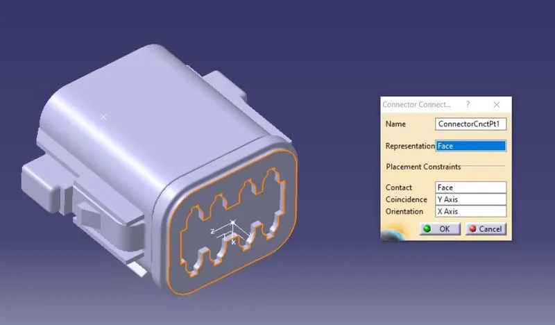
Then Define its Connector Connection Point.
3.C0085229-01-03 Mounting Clip.
Define as Cavity to mount connector on it.
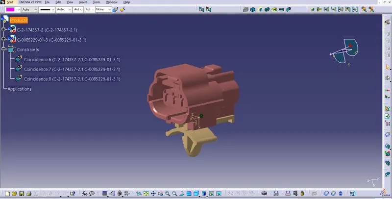
Making Assembly of Connector and Mounting Clip which previously defined as electrical component.
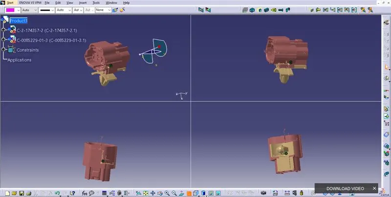
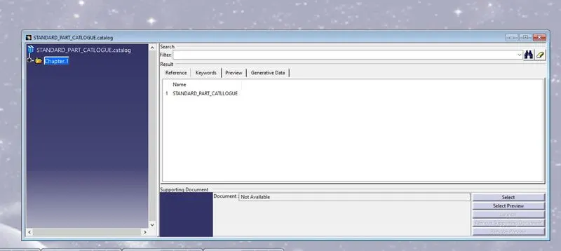
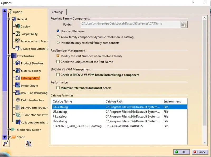
Defining Standard Catlouge to store all standard component.