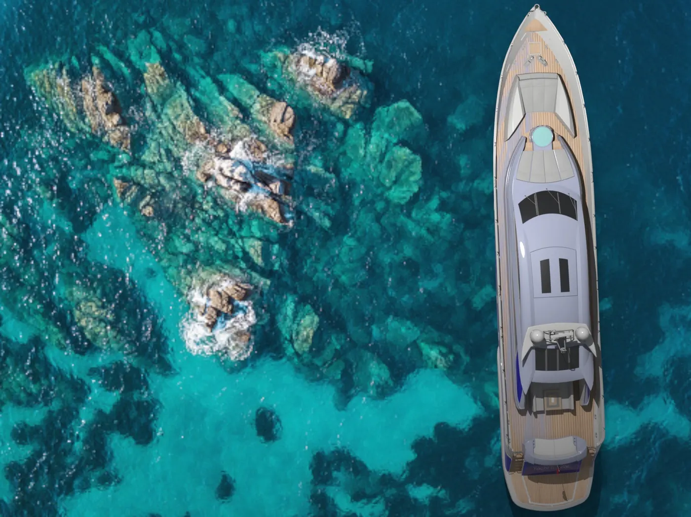
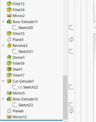
Radar Mast & Final Assembly of Yacht
**********************
Design and Assembly of YACHT in Solidwork
Aim & Objective
- Design and assembly of the yacht in solidework.
- To learn the surface modeling features in the solidwork.
- How to model and design using blue prints and modeling the parts and structures of the yacht.
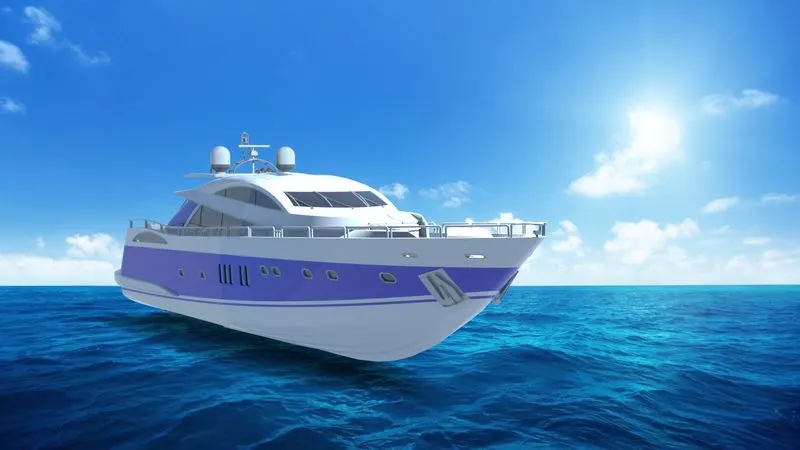
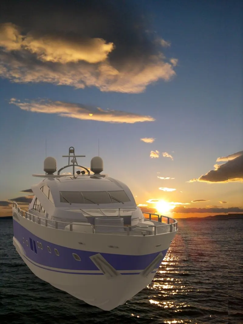
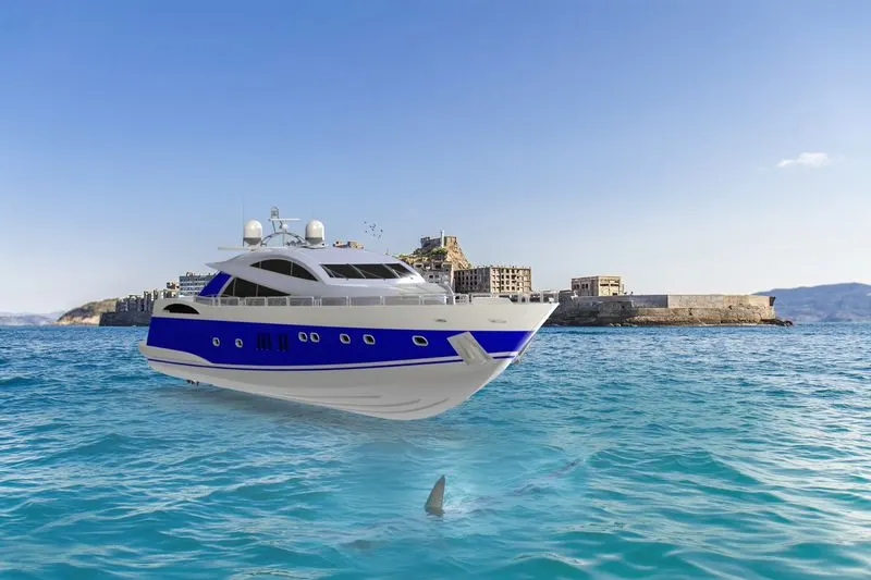
- Render the yacht model in the solidwork visualize with some sea backgrounds.
Introduction
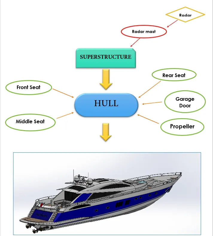
In this project we are going to learn how to create solid parts with blue prints using the surface modeling features int the solidworks. Here we designed the yacht using its blue print, we designed its base part called Hull, Superstructure, Propeller, Radar, Radar Mast, Garage door, after all the part designed applying colors to them. After all the parts designing, modeling & coloring completed we did the assembly of the yacht in the solideworks assembly. Last we did the rendering in the Solidworks Visulize with some sea background.
List of the Components which we are learnt in YACHT
- Propeller and Radar
- Hull and Garage door
- Front Seat, Middle Seat and Rear Seat
- Superstructure
- Radar Mast
FLOWCHART
List of the Features to Design the YACHT
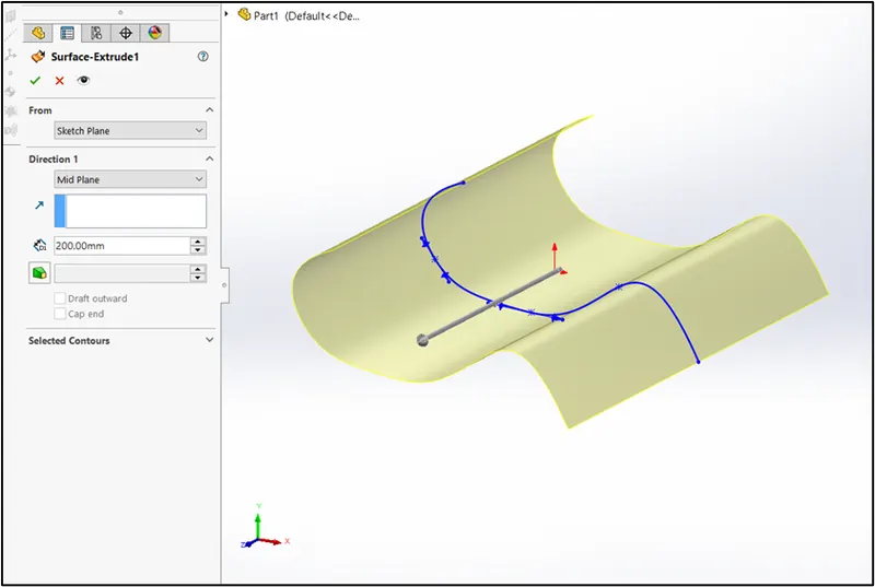
- Extruded Surface
This feature used to create a surface from the line or given sketch we draw, this is an basic feature like the extruded boss.
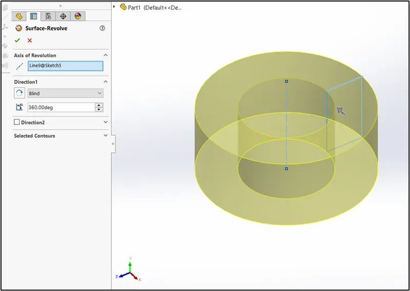
2. Revolve Surface
It revolve sketch or sketch counter around an axis to create surface.
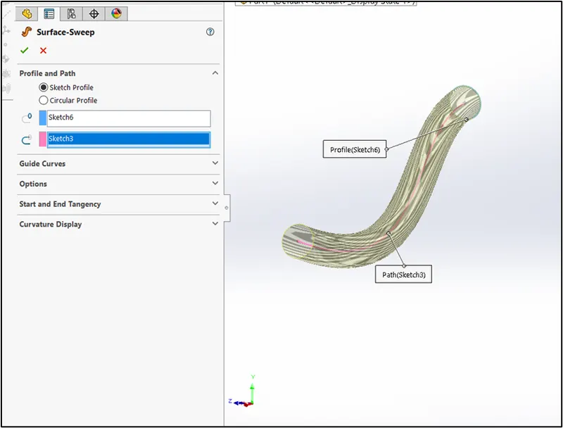
3. Swept Surface
It sweeps a closed profile along an open or closed path to create a surface. we can use guide curves, profile orientations and twist angles to different shapes.
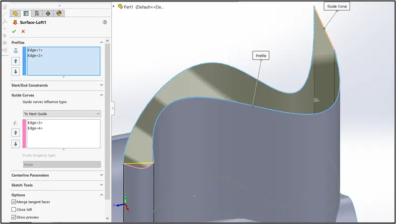
4. Lofted Surface
It allows us to create a lofted surface between two or more profiles or sketches. Specify start and end constraints and add guide curves to control the path shape.
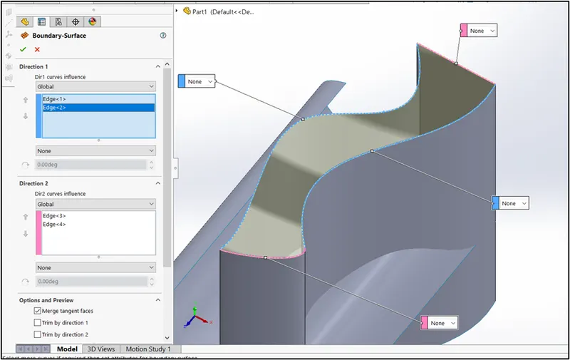
5. Boundary Surface
It creates a surface between profiles that can be tangent or curvature continuous in all direction. In the graphics area, use connectors or instant 3D drag handles to shape the boundary surface.
6. Filled Surface
This feature le use to fill patches a surface within a boundary defined by edges, sketches or curves. Use constraint curves to fill surfaces and adjust resolution control to improve surface finish.
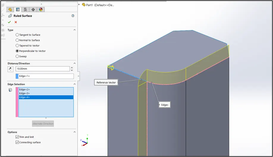
7. Ruled Surface
It allow us to insert ruled surface in a specified direction from edges. You can trim and knit the surface and remove connecting surface.
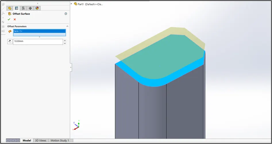
8. Offset Surface
It creates a offset surfaces using one or more contiguous faces. The tool creates an offset surface with gaps. You can repair the gaps manually or just the offset distance value and run the tool again.
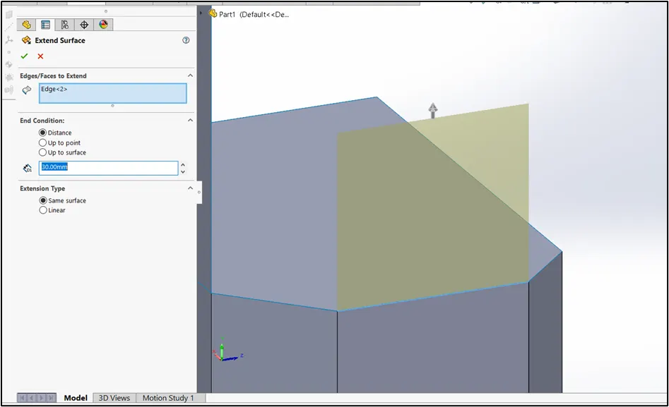
9. Extend Surface
It extends one or more edges or faces on a surface, based on end conditions and extension type.
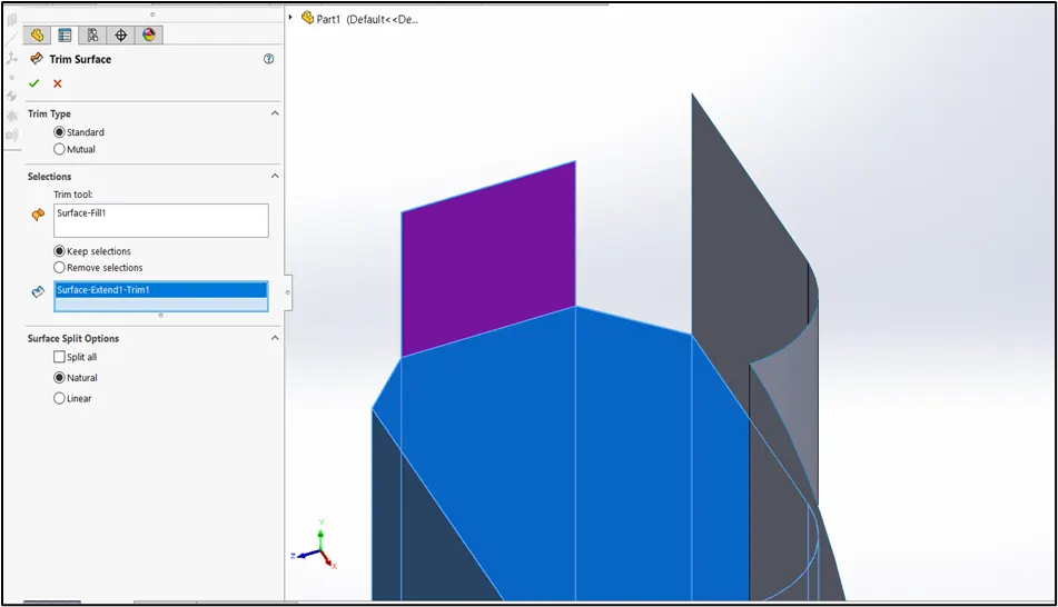
- Trim Surface
This feature allow us to trim where a surface intersects with another surface, a plane, or a sketch. Select a trim type, trim tool and the surface to keep or remove. You can end points of the trim tool.
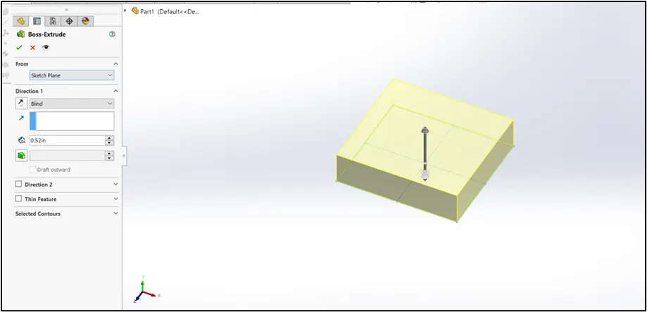
- Extruded Bass/Base
It is use to get solid body of the sketch and the sketch should be fully defined.
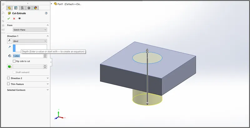
- Extruded cut
It is used to cut part from the solid body to get desired shape of the body.
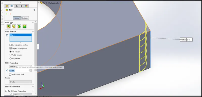
- Fillet
It converts the sharp edges in to round and smooth shape with given radius.
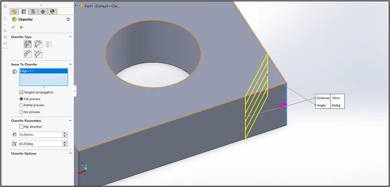
- Chamfer
It creates a slopping symmetrical surface at the selected sharp edge.
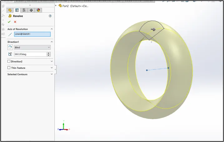
- Revolved bass/base
It revolves the sketch around the selected axis and creates a solid form from the sketch.
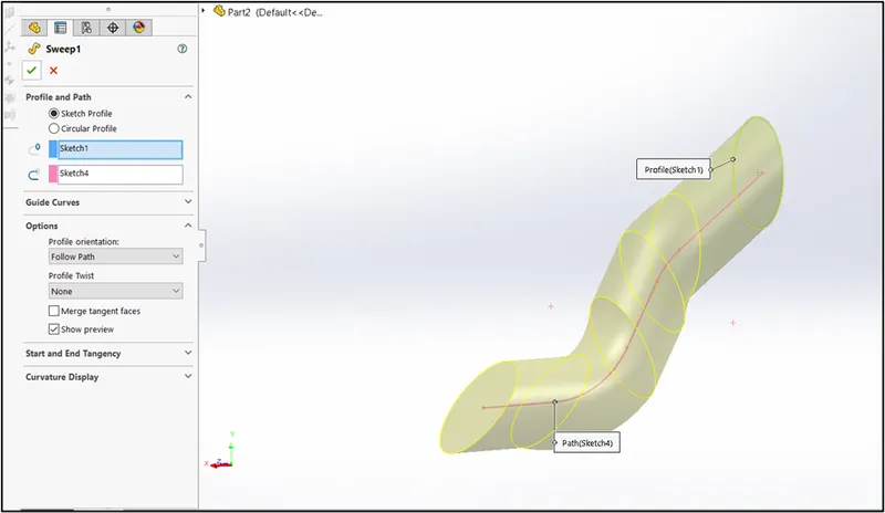
- Swept boss/base
It creates a solid body b closed profile along open and closed path.
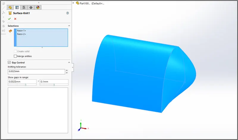
- Knit
It combines two or more adjacent, nonintersecting surface in to a single surface body. The surface must join the edges, if the resulting knit surface encloses a volume, you can create a solid body from property manager.
- Sketch
It gives us the work base to sketch our 2d or 3d geometry.
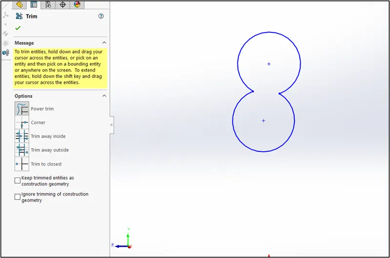
19. Trim entities
Using trim we can cut out all the unwanted sketch from our geometry.
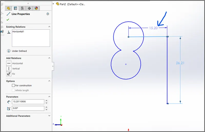
- Smart dimensions
Using smart dimension we give desired length to our geometry and locate the geometry at desired location.
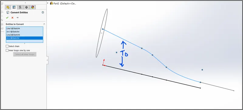
- Convert entities
It converts selected edges and sketch entities into identical in entities by projecting them on to the sketch plane or face.
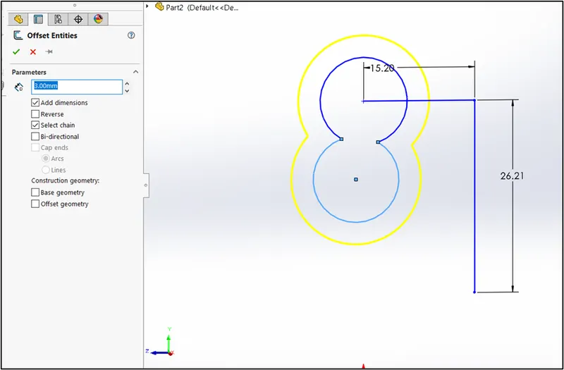
- Offset entities
This feature allows us to offset one or more sketch entities by a specified distance. For example, create a line from the selected line. It the original entity also changes when you rebuild the model.
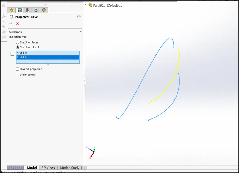
- Projected curve
It combines Two 2D curves in One 3D curve.
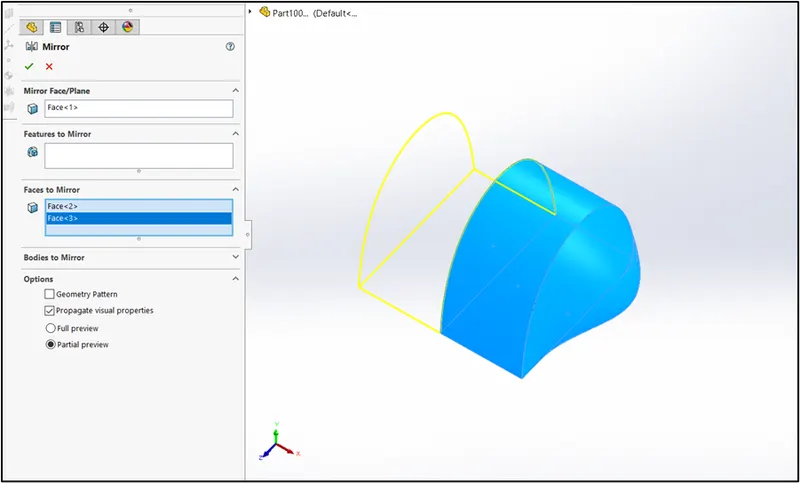
- Mirror
It allow us to mirror the geometry or the solid body from the selected reference.
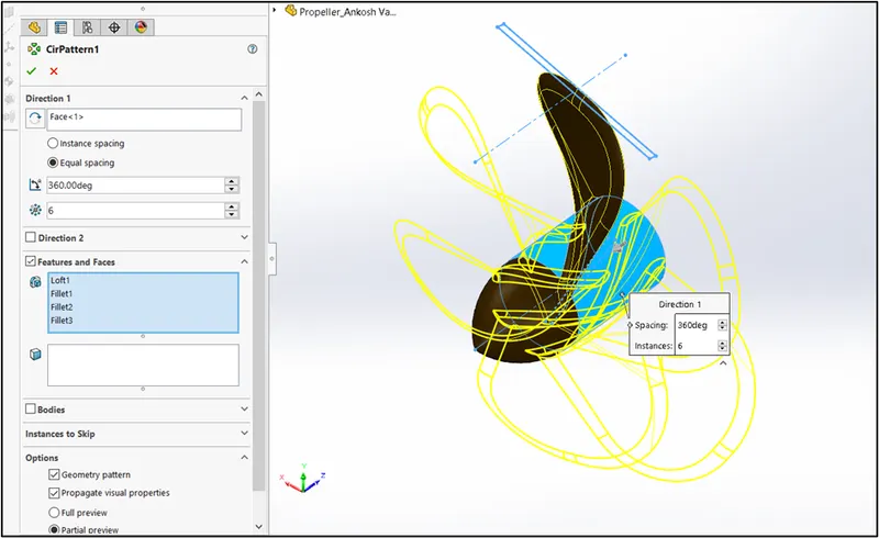
- Pattern
This feature allows as to crean the multiple copies of the same sketch or the feature aong with same referene sketch or feature with guid line, curve or we can say a path for the pattern.
*****
- As we discussed all the sketch tools and freatures and their uses used to design the Yacht.
Now we going to explain how we designed the parts and the strutures of the yatch, as follows
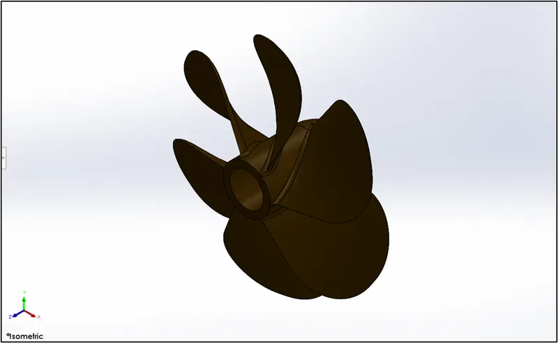
- Propeller
A propeller is a device with a rotating hub and radiating blades that are set at a pitch to form a helical spiral, that, when rotated, exerts linear thrust upon a working fluid, such as water or air.
Procedure:
Step 1 : sketch on the right plane draw 350mm horizontal line from origin and two vertical line to the end point of the line, from the left side vertical line draw horizontal line towards right side and connect the right end point of the line to right vertical line with spline and. Drag the upper handle of the spline and give it horizontal relation. Use revolve bass feature to revolve it around its axis to make a cylindrical solid body.
Step 2 : create reference plane 360mm above the top plane and draw 3 point centre rectangle with hight of 400mm and width of 12mm give 14 degree angle to longer face of the rectangle and the remaining dimensions. Draw again a 3 point centre rectangle on top plane with same dimensions and give angle 75 degree from horizontal to longer side.
Step 3 : using lofted boss select both the rectangle and create twisted plate like body. D0 fillet to its top edges to make the sharp edges round do circular pattern over the revolve body and do circular extruded cut to from the centre of the body
apply colour
Tolls and feature used
Sketch tool : line, spline , circle , 3 point centre rectangle.
Feature : Revolve boss, lofted boss/bass, extruded cut, fillet.
Colour : Brown
- Radar
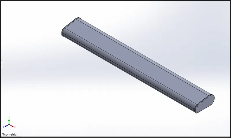
Radar ( radio detection and ranging) is a detection system that uses radio waves to determine the distance ( ranging), angle, or velocity of objects.
Procedure :
- Sketch on the right plane draw horizontal line 200 mm line from the origin and two vertical line 100 & 65 to right end and left end of the horizontal line connect the vertical lines with inclined line and do extruded bass using mid plane option and apply fillet to its both end edges.
- Selecte side face of the extrude body draw sketch on it. Using that face do offset of 3mm outward, exit and do extrude. Draw again on the second extruded body dra small circles and copy them on right side and at downward side. Do extrude male bolt like structure apply fillets and chamfer. Do mirror of the second extruded body and the bolts to the mid plane. Do extrude cut at the bottom of the radar.
Tools and features used
Sketch tools : line, circle.
Features : Extruded boss/bass, Extruded cut, Fillet, Mirror, Sketch pattern
Colour : White
- HULL
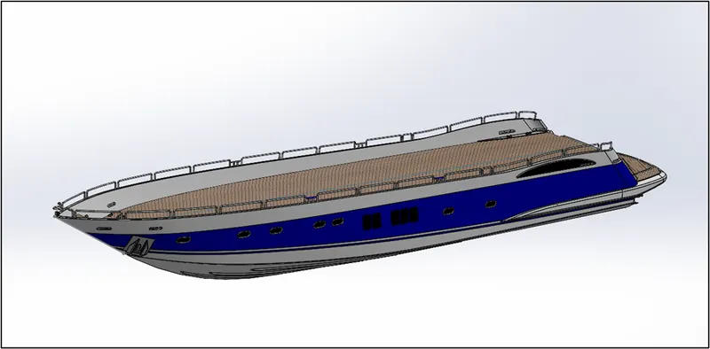
Hull is a portion of a boat that ride both the in and on top of the the water.
Procedure :
- Sketch on the bottom plane draw lin and spline adjust the spline handles to match the sketch with the blue print. Make sure that the right end of the line is coincident with the back plane. Dra another sketch on the top plane match the skech with the blue print and exit. Do projected curve use select the bothe the sketches to make projeted curve. Do same for another projected curve.
- Connect the both end of the projected curve according to the blue print. Sketch on right plane connect the right left end of the projected curve with spline and drag the arrow to match with the blue print. Give diamensions. Sketch on bake plane draw spline to connect the ends of the projected curves give diamensions and exit.
- Now using the loft surface feature to create a surface : first selecte the two lines as a profile and select the two splines as guide curve make sure that the surface is coming properly or else adjuct the green balls to create, using curvature display you can chech your surface is coming is properly or not.
- For other surfaces do the same as step 1,2 and 3 , draw the lines and splines match the sketch with the blue print give it appropriat diamensions do projected curve and so on.
- After all the surfaces created trim the unwanted sufaces and knit them. Then use surface fill t0 close the volume and then apply shell feature of 160mm. then sketch on the mid plane select the outer edge of the hull and offset it 15 mm inward. Using that sketch do extruded surface using up to next option.
- For windows : sketch on the mid plane dra the sketch of windows using line quares and sraight slots to sketch. Do extude cut using offest form the surface option change the direction if direction is wrong then create a reference surface taking references from the window corner and vertex, sketch on that plane draw circle and connect its centre point to the origine, do sweep boss/bass use the window edges as path and do the sweep.
- For the grills: sketch on the mide plane draw the vrtical and horizontal line,splines to match the sketch of the grills in the blue print applay dimensions and exit. Sketch on the top plane selecte the outer edge of the hull and offset it 15mm inward it is the path of the grils. Now do the projected curve slecte the bothe sketches you can see the projected curve on its place. Create a reference plane using left end point and the curve itsel of the projected curve and sketch on it and draw circle and coincide its centre point ot the origine and do the sweep using the grill projested curve as path.
- For stair : sketch on the one of the end faces where we did the extrude cut and draw vertical and horizontal line make stairs like structure and extrude it up to next.
- For the shaft : Sketch on the mid plane draw hoizontal and vetical line to match the sketch with the blue print, give appropriat diamensions, using the revolve boss/bass revolve that sketch to its axis. Apply fillets and chamfer to the sharp edges. Sketch on the end face of the deck draw a inclined line upward from the center of the shaft, give 69 degree angle to the inclines line from the vetical plane. Using linear pattern patter the saft aong the line use line as path for the pattern and give 1600 mm distance.
- After all the designing of the parts are completed mirror the body using mid plane as mirroring plane, apply colours and decals.
Tools and Features used to
Sketch tools : lines, circles, rectangles, 3d sketch, split line, straight slotes, convert entities, offset entities.
Features : Surface extrude, knit, Surfae fill, Shell, exturded boss/bass, Extrudes cut, Fillet, Chamfer, Swept boss/bass, Dome, Helix, Pattern, Projected curve, Referenc Geometry, Split, Mirror,
Colour : White, blue, Grey, Black.
- Front Seat
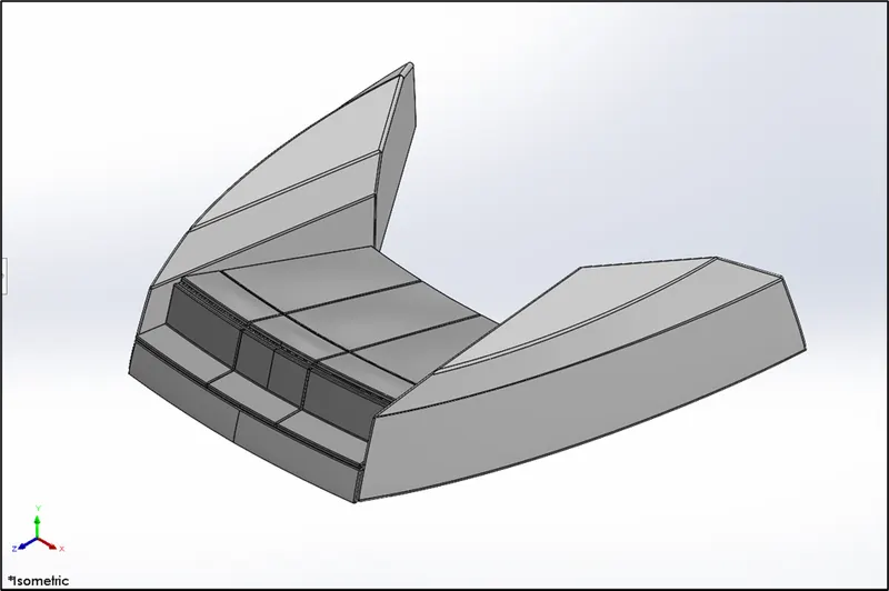
Front seat its place at the front of the yacht where people spent their time for relaxation.
Procedure :
- First we import the surface of the hull and use it as a reference. Sketch on the front palne draw splin match with side of the front seat in the blue print, then sketch on the top plane draw spline match with the blue print and do surface sweep us the sketche first sketch as profile and second spline as a path. After that sketch on the top plane sketch as the dimenstion given and match the sketch with the blue print. Extrude it use the vertex of sufrace sweep to extrude at its lecvel.
- Trim unwanted parts using trim surface feature and for triming use the surface extudes and sweeped surface to trim till the desired shape then draw line on the top plane mat ast te sketch and use it as a trim tool for triming the surface form the top of the seat.
- Use lofted surface for the gab between the uppwe surface and its adjucent surface . for that use the edges of the upper surface and the its aducent surface whichi is vertical. Use one edge from the upper durface and one edge from the vertical and select two vetical edgeds adjacent along with the vertical face as guide curve.
- Now select the inside face of the seat and sketch on that draw 200mm vertical line and 8450mm horizontal line from botom left end vetex of the seat now sketch the remaining part fro the inclined seat now draw construction line from the left bottom endpoint toward left side and exit. Do swept boss/bass option use the verticle construction line as axis and give 10 degree angle to sketch and do the sweep.
- Now for the matteres over the inlcines surface sketch on the inner face of the side body and offset from the inclined surface of 45 mm and do sketch remaining lines and do the sweep bass base as the inclined suface for 10 degree then apply dome over it apply fillets to the sharfe edges and aplply colour.
Tools ahe Features Used
Sketch Tools : line, Spline, Convert entities, offset entities.
Features : Sweep surface, Surface extrude, Trime surface, loft surface, Knit, Surface fill, Chamfer, Revolve, Extruded cut, Fillet, Mirror, Dome.
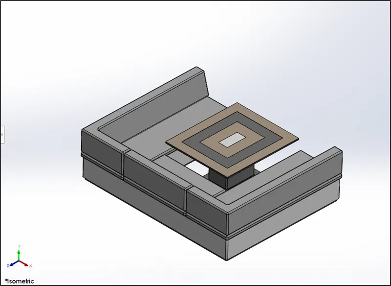
- Middle Seat
Procedure : Like the front seat import hull surface and use it as reference face.
- Sketch on the surface draw upside down ‘L’ like sketch of 675 mm wide of 2000mm vetical and 1280mm horizontal, give diamention of a 3264mm horizontal from right end. Extrude it 35 mm, sketch on the extuded surface give offset to the surface sketch of 4 mm split tem from the perpendicular area an extrude 2 individul body of a 75mm hight.
- Sketch on the extruded body and offset the outer line 250 mm inside make closed rectangles and extrude it 350mm . then apply chamfer using distance distance option an apply it to upper inner edge.
- Now sketch over the reference surface again draw rectangle and give 300 mm diamention from each side using the seat and surface and reference then draw again on the extrude rectangle extrude it above and design like the centre table do extruded cut on the surface of the table to styling. Apply fillets to all the edges and apply colour.
Tools and Features used
Sketch tools : Line, Rectangle, Offset entities
Features : Extruded boss/bass, Extruded cut, Chamfer, Mirror, Fillet.
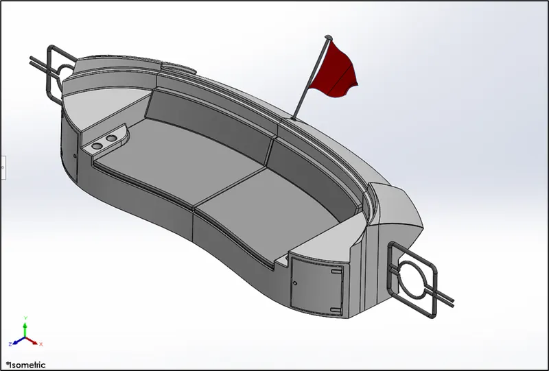
- Rear Seat
Procedure : insert the hull surface for the reference
- Sketch on the mid plane spline and drag their handle to match sketch with the blue print and give it apprpriat diamension an this geometry should be 300mm inside from the right end. Sketch on the top plane draw splien 2400mm horizontal from centre to right and give 1140mm vertical, drag the spline handles to to match the curve with the blue print. Now using swept surface sweept the first sketch using the horizontal spline as a path.
- give 50 mm offset to sweep surface outward, draw 100 mm vetical line 1400mm left to the centre and to trim the the offeseted surface half. Then use ruled surface to connect both suface at top edges, knit bothe the durfaces, use loft surface and selecte the edeges of the offeset durface and the man sweep surface and use ruled surface as guide curve. Use surface fill at the bottom and lofted surface at the side to close all the open faces the extend an tream some edges to make sure that all the edges are intersecting and there is no gap between them.
- Kint the all the surface created and make a solide body.
- Sketch on top plane draw line spline and give them diamension and match the sketch with blue print at the matress part. Extrude that and sketch over it to creat the arm rest side and cup and bottle holders, for that extrud some surface and do circular extruded cut to make bottle holder and softdrink holder.
- For the matteres. Select the face of first extruded boss/bass apply surface offset of 5 mm then sketch over the offset surface using offset entities offset inward 5 mm and then extrude it 60 mm to make the mattres. Apply fillet to its all the sharp egdes and and mirror it about the mide plane.
- Flag stand : sketch on the mid plane dra verticle and inclined lines to make like the stand as in the blue print and do the revolve at its own axis.
- For the flag : for flag use 3d sketch draw four 3d sketche and use lofted surface to make the flag .
- Aplly colour
Tools and Feature used
Sketch tool : Line, spline, circles, rectangle, convert entities, offset entities.
Features : Swept surface, Surface offset, Trim surface, Knit, Extend surface, loft surface, filled surface, Extruded boss/bass, Extruded cut, Fillet, Chamfer, Swept boss/bass, Mirror, Revolve.
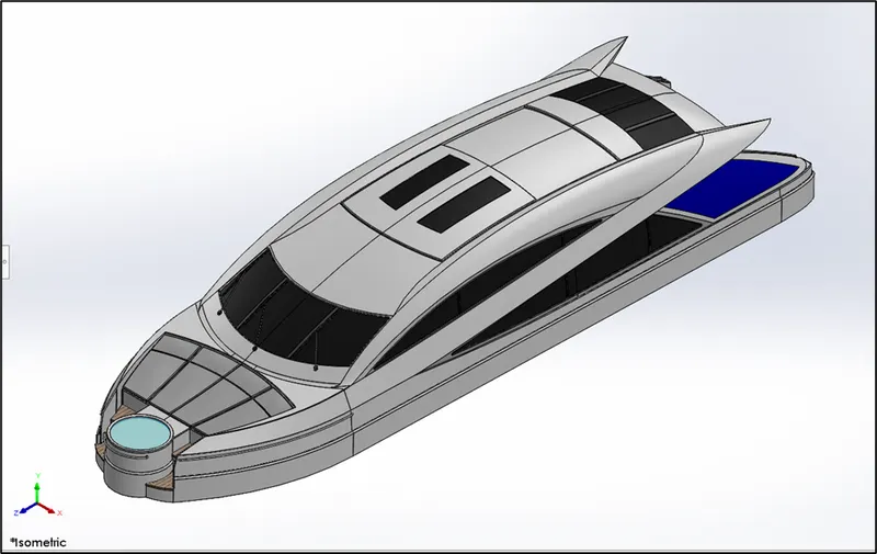
- Superstructure
Super strcture is a like a cabinet which involves driving area or a living area of the yacht or in boat.
Procedure: the procudure of the superdtrucure is Same as the hull part creating projected curve loft surfaces, trim the surfaces an knit them all int one solide body then apply fillet and chamfers its same for the surface created in hull
For jacuzzi : for the jacuzzi sketch on the surface the draw a 1460mm circle give it dimention from the refereces to locate it at its place and extrude it 600mm upward, sketch on the extruded surface face and draw two circle and give them diamension 100mm and 35 mm from the outer edge of the circle. Extrude it 560mm upward, apply fillet at its upper edge and middle edge. do extrude for the water level in jacuzzi.
For the wind shield : for windshiel draw sketch on the top plane and do the draw the sketch for the windshield and do extruded cut from the surface and selecte surface.
For the Vipers : fot the vipers sketche on the top plane draw the rectangles and do the extrude from surface select the surface where the viper to be extruded. Apply distance distance chamfer to both upper edges. Then apply fillet to all edges. Now for the conection of the rod. Draw 3d sketch to its mid area, creat plane using the 3d sketch to its end point and draw circle, sweep that circle using the 3d sketch as as path.
Apply color
Tools and Features used
Tools : Line, spline , circle, rectangle, offset entities, convert entities, 3d sketch, split lines.
Features : surface extrude, sweep surface, knit, fillet, rulled surface, projection curve, loft surface, extruded surface, extended surface, trim surface, extruded boss/bass, extruded cut, delete face, dome, mirror, chamfer.
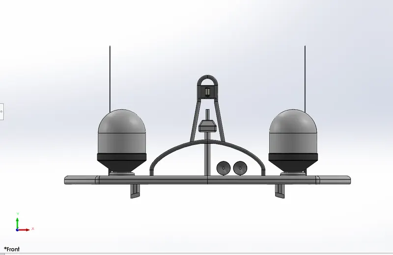
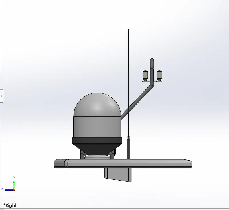
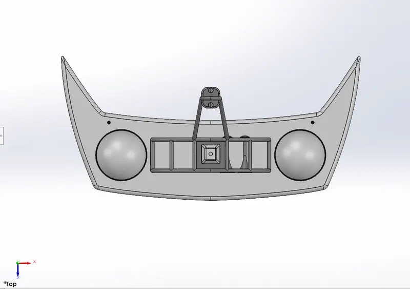
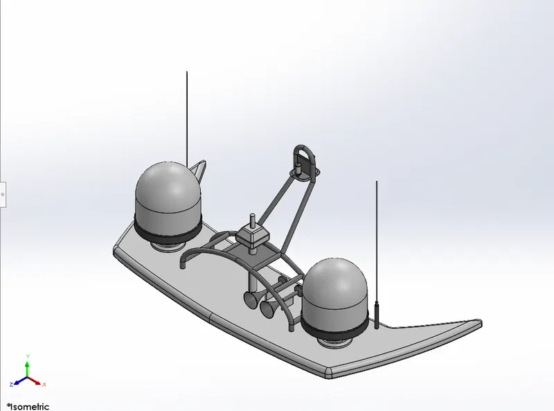
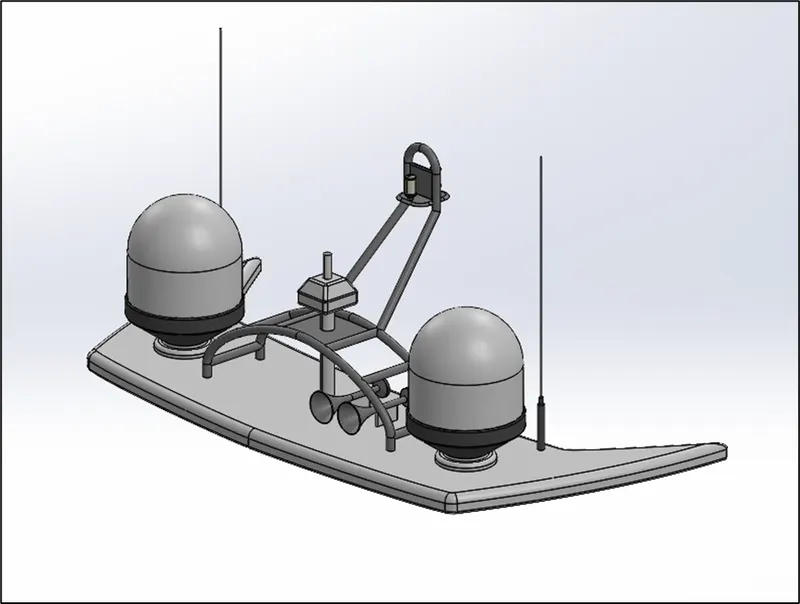
- Radar Mast
Radar masts are electronic nevigation instruments that use rotating antenna. It detectets the targets by microwaves reflected from them, generating ships surroundings on the display screen.
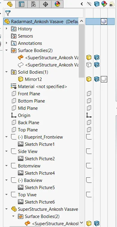
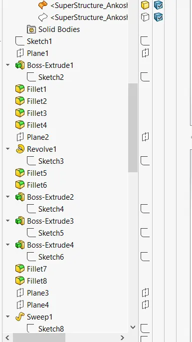
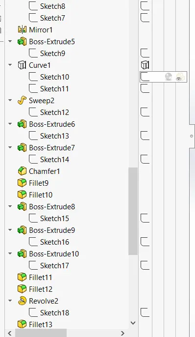
Procedure : import the the radar mast face from the superstructure.
- Sketch on the mid plane draw 820mm horizontal line 160mm above the reference surface, using this sketch add new pane, sketch in it draw lines and splines give them proper diamension and match the sketch with blue print, extrude it 140 mm and aply fillet to its edges.
- Create a reference pane from front plane 20950 mm toward the extuded body, now sketch on the that surface, draw verticle line and center pont arc to draw the sketch as the blue print, apply diamensions and revovle it to is own axis to create circular and conical body.
- Now to ceate antenna sketch on that extruded body face draw circle of a 50 mm the extude 345 mm upward now draw on that exturded circle face draw 30 mm circle and extrude it again sketch over the face of recently extruded circle draw circle of 10 mm diametere and extrude it 1800 mm in upward direction
- Sketch on the pane that we created dra vericle line and spline as the grilles showd in the blue print apply diamensions exit, sketch on the mid plane draw a verticle line and apply diamensions. Do projected curve and creat reference plane to the projected curve end draw circle on it use piears relation ot connect center of the circle and projected curve , sweep the circle using projected curve as a path. Crate some extrude bass and apply fillets and chamfer to create the bulb. Mirro the bulb and extrude part alonge the plane created.
- Mirror the radar mast body to the mide plane, knit and merge results, apply colour.
Tools and features used
Sketch tool : lines , splines , circles, rectangles, conver entities.
Features : Extruded boss/bass, Extruded cut, swept boss/bass, revolve boss/bass, mirror, projected curve, shell, dome , fillet, chamfer.
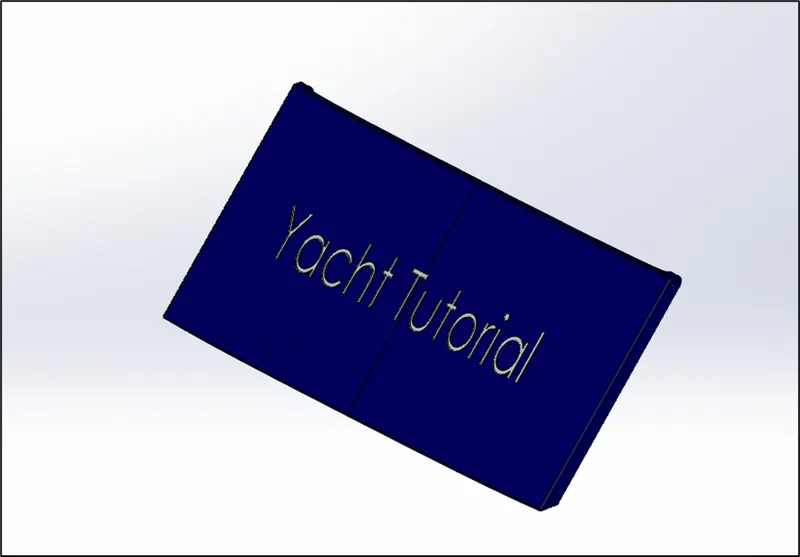
11. Garage door
Procedure : import the stock body from the hull, draw on the mid plane and cut the unwanted part using extruded cut, then use shell selecting the bottom face, apply fillets , then sketch on the thin face of the body draw circle give diamensions exit, use extrudes cut of distance 100mm distace. Mirrot the body to mid plane and apply colour.
Tools and features used
Sketch tools : line and circle.
Features : Extruded cut, shell ,fillet mirror.
***
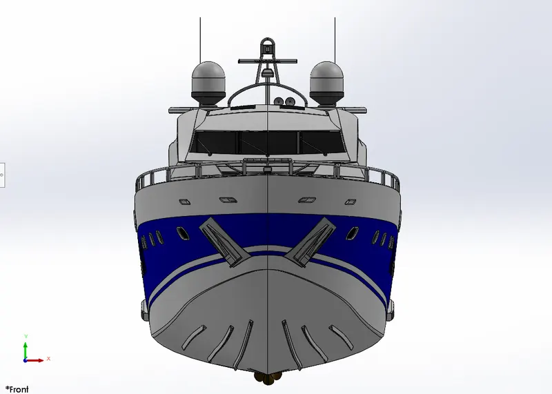
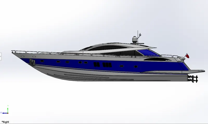
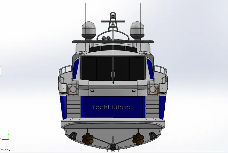
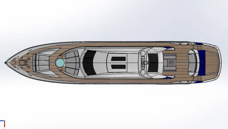
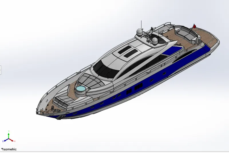
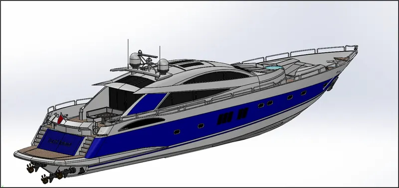
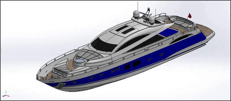
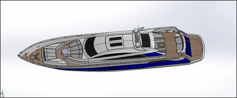
All the parts design are completed now we assemble all the parts in solidworls assembly as follows
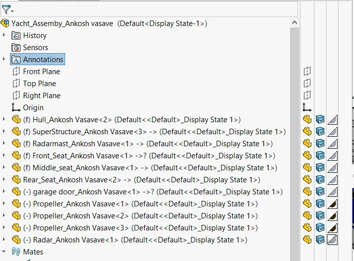
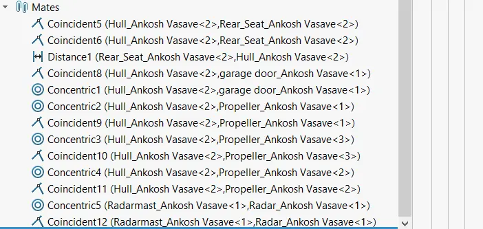
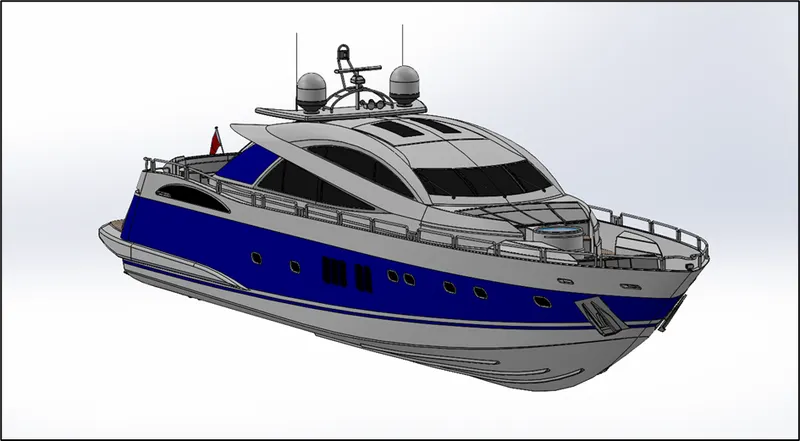
Now insert the hull part first and thene insert all the parts one by one, make sure that the part are at their respective places and give their mates respect to the hull. Apply concentric and coincident matesd to the propeler and shafts make sure that all the 3 shafts are at their place, then apply concentric and coincident mates to the radar and radar mount asembly completed.
Samples of the assembly
CONCLUSION: After completing this project we leaned the features of the solidworks mainly the surface feutres of the soliworks which we can model or design now any kind of parts using the blue print. We leaned very well how to use the surface loft and other surfasing features .
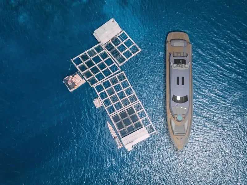
Here some renders in the solidworks visulize