Week 9 - Project - Master Section Development
TOOLING AXIS
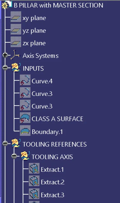
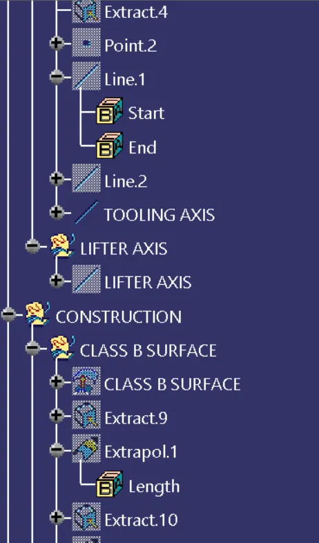
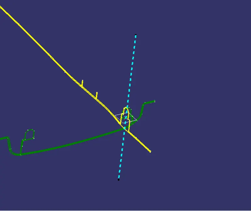
To create tooling axis extract the lines from the master section create the , then using these master section create a point in center of that lines, then create a bisecting line using these lines and point and name it as Tooling Axis.
then create SIDE CORE TOOLING AXIS
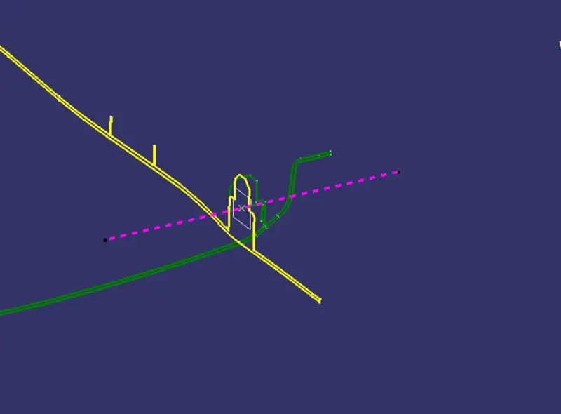
To create side core tooling axis create plane at the center point using YZ plane rafference. then create line at the using the point and the line.
Draft Analysis of CLASS A SURFACE
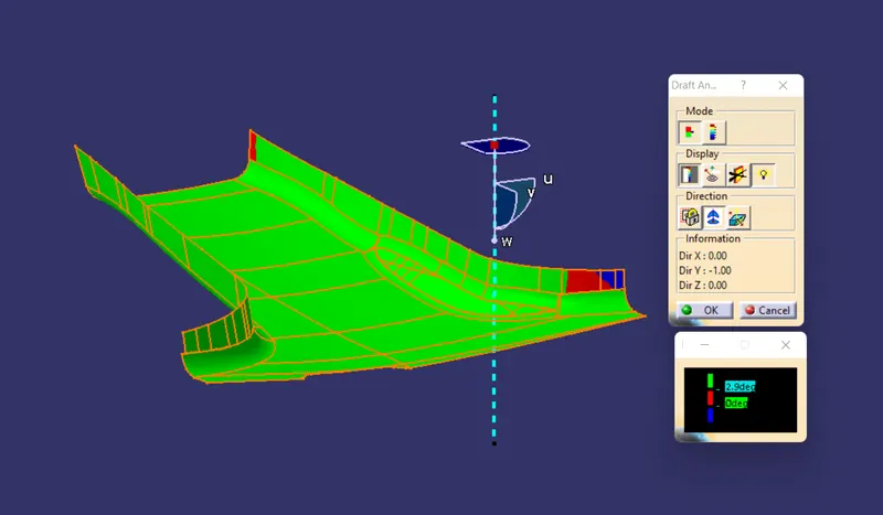
Green colour represents the angle with tooling axis in that surface area is 3 degree and more than 3 degree.
Red coolur represents the angle with tooiing axis in that surface is between 0 to 3 degree.
Blue colour represents the angle with the tooling axis in that surface area is negative.
left side class a analysis
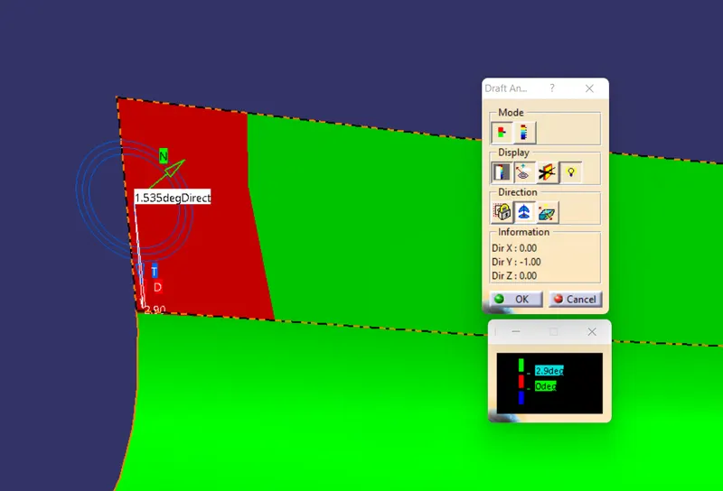
minimun angle at the right side red surface area is 1.535 degree.
left side red area
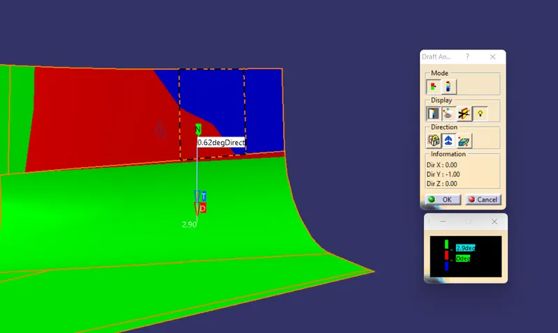
minimum angle present at the surface is 0.62 degree.
left side blue area
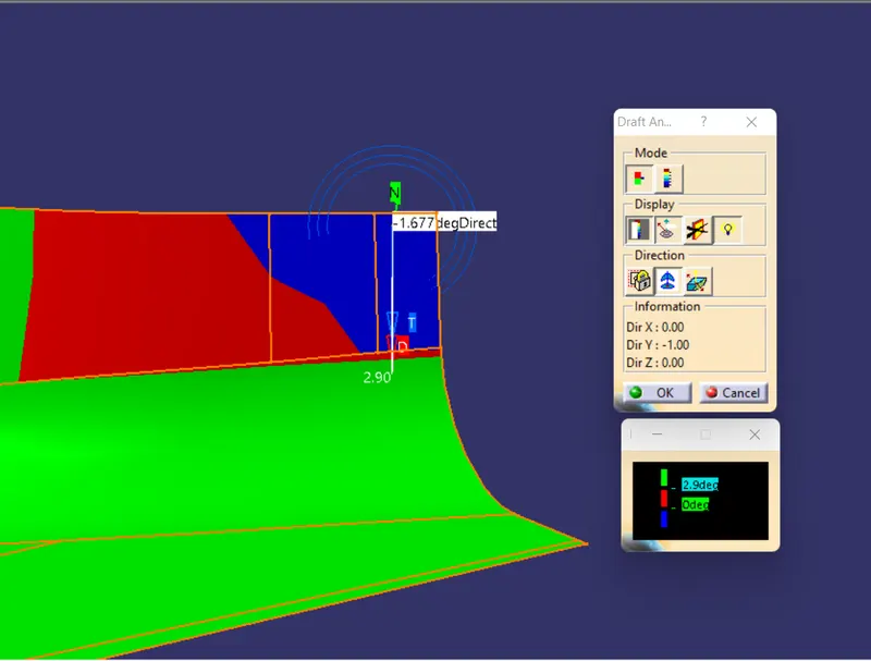
maximum negative angle present in that area is -1.677 degree.
so as we can see the class a surface is not perfect like there is a area at the left and right side it shows red and blue, it means the class a surface needs to be corrected so we have to report this error to the class a deisgner and aks them to correct the class a surface.
Class B Surface Creation
to create the class B surface we offseted the class a surface by 2mm.
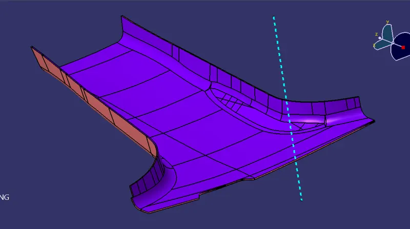
CREATION OF FLANGES
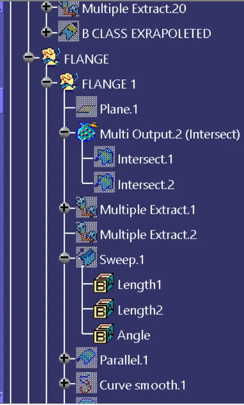
Then we have create the flanges which shown in the master section. extract the edges and adjusent surface of the egdes of the class A surface from both sides. use sweep command and sweep that line use tooling axis as pulling direction give 90 degree angle to the sweep with pulling direction and make sure the arrow we chosen is pointing outward.
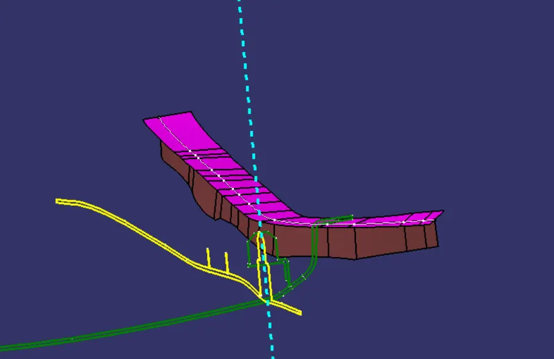
make plane over the green mastersection and create plane parelle to it then take a intersection of the sweep and the mastersection to make sure the sweep is maching with the inputes.
of not then we have to increase or decrease the angle to match the sweep with the intputes. over here i have to increase the angle value from 90 degree to 95.9 degree to match it with the inputes in master sectipon. do same for the other side also
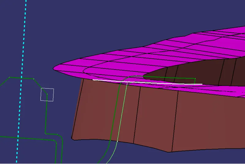
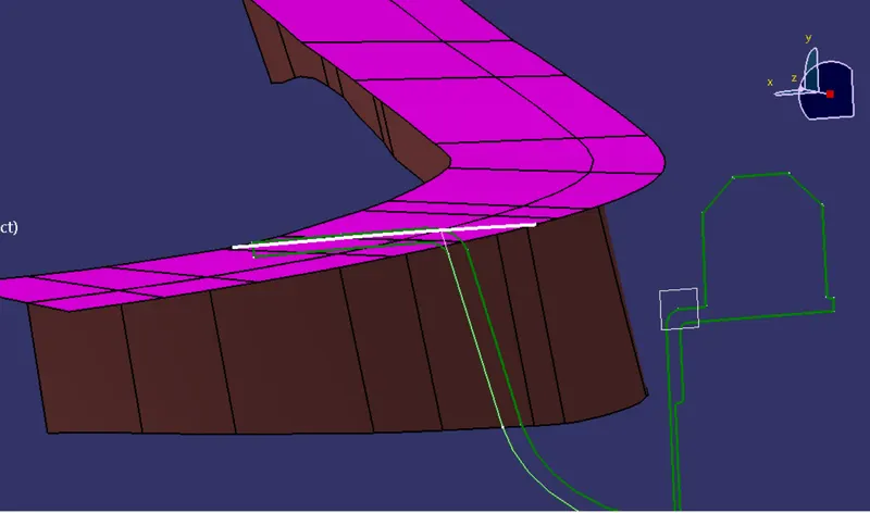
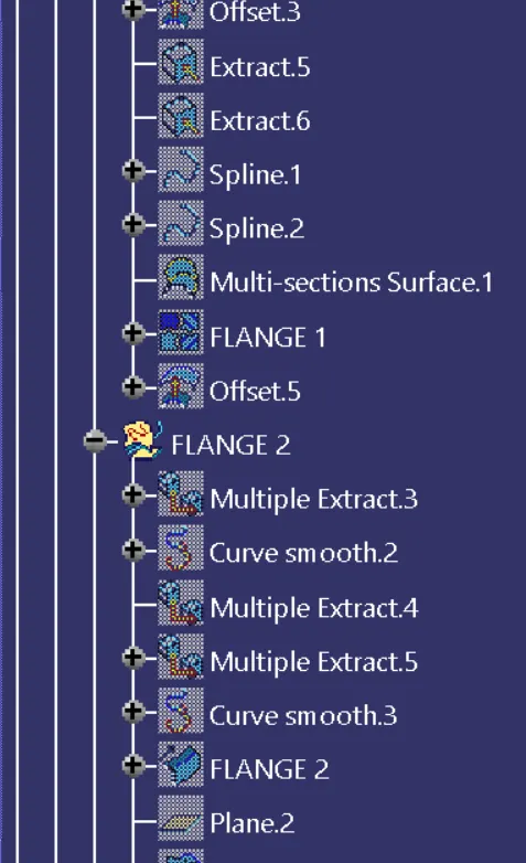
then offset both the sweep uside by 2mm and trim them with the class B surface to make the class B with Flanges
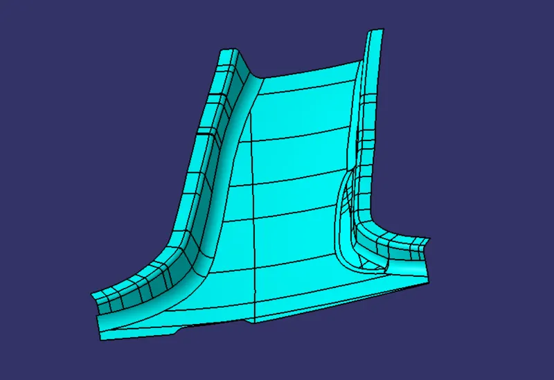
the class b surface is completed
Creation of Class C Surface
to create the class C surface we extracted the edges of the class a surface and then sweeped them along the tooling direction of an angle 3 degree. check all the sites and se if the surface which are sweeped is intersecting to ecah other or not, if not extrapolate them and trim them togethe to form a class C surface.
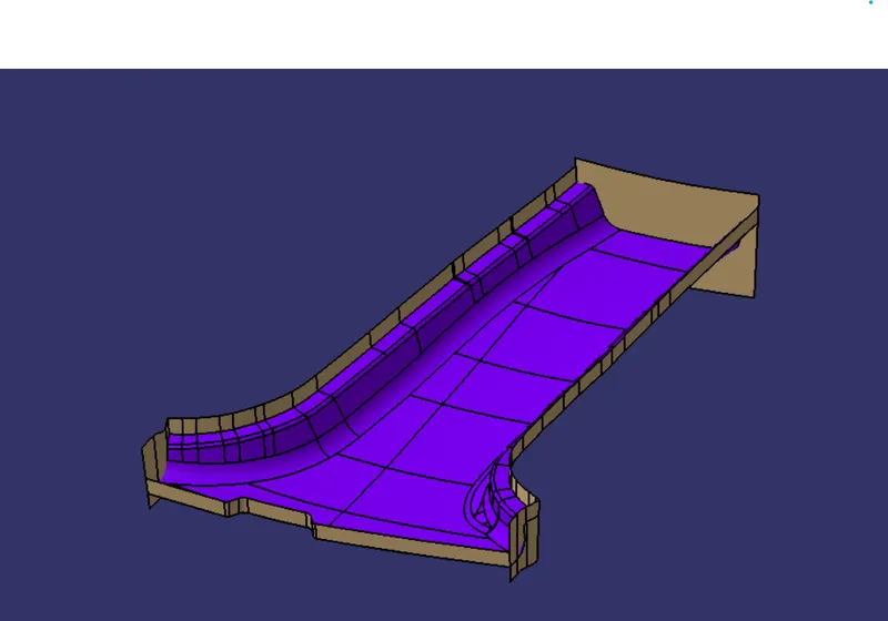
FINAL SURFACE
trim the class A with class C , then trim the with Class B to form a final surface
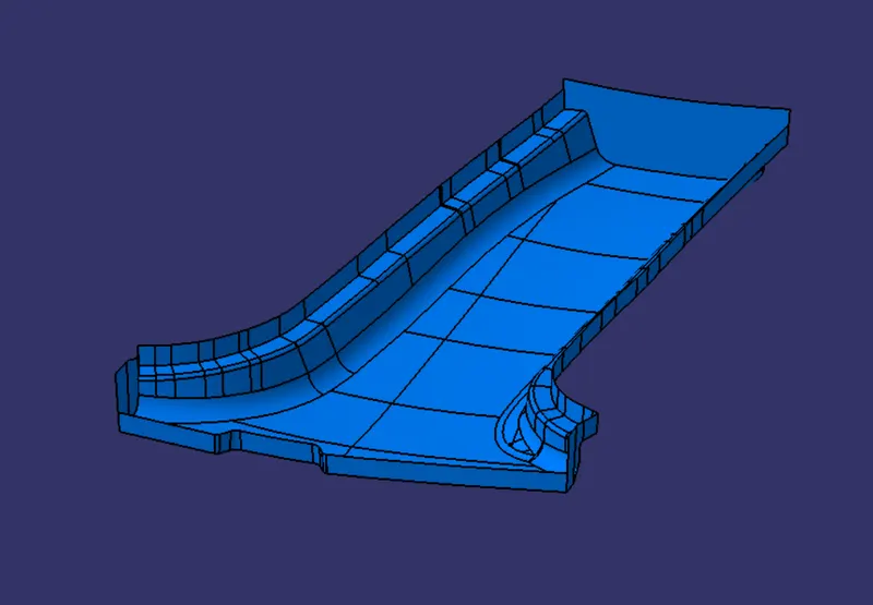
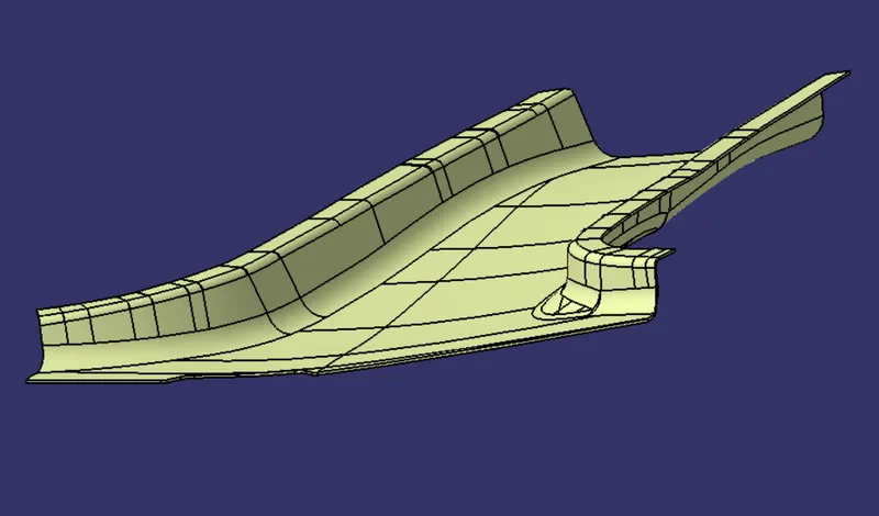
Creation of Close Surface
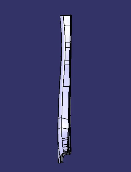
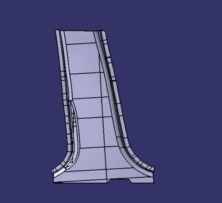
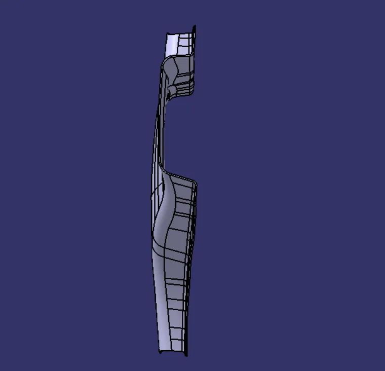
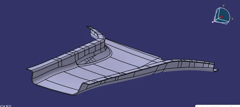
Draft Analysis of Close surface ( B PILLAR )
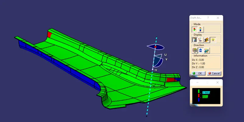
The all part are green that means its 3 dgree or above it except the red blue on ledt side and and red at the right side this because of the we have class a like that, because of the class a we have a component like that, when class A surface will improve then the component is aslo going to be improved.
CREATION OF DOGHOUSE AND 4 WAY LOCATORS
to create doghouse we created a plane to sketch on the midpoint which we created at very first to create the tooling axis, we going to create plane on it then sketch on it.
sketch on the nwe plane, thake the proojection of the master section then isolet the ptojection then extent the lines so it can be extend enough to get out of the component.
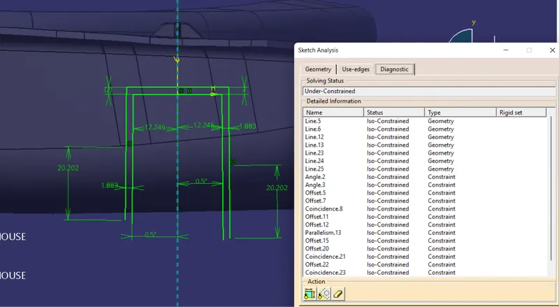
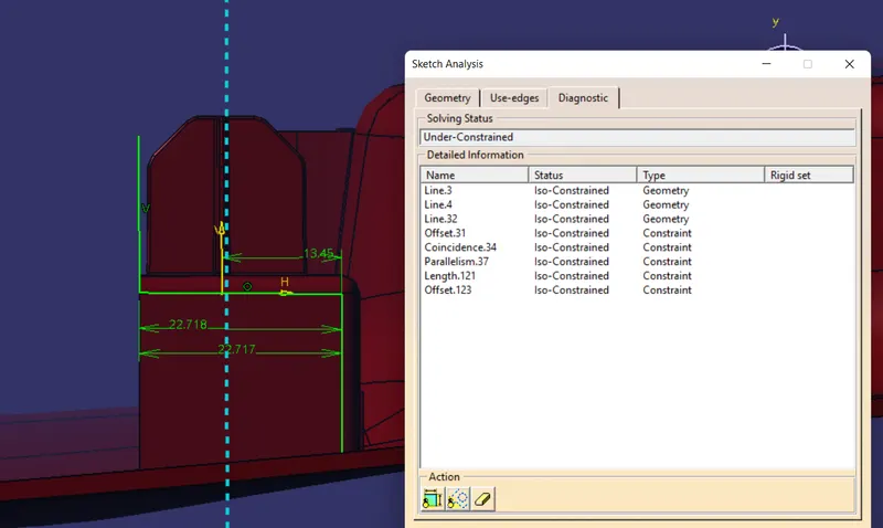
then exrude the both sketch and them trim them together to make the rquired shap and thiken them using the thick command in to part workbench
after that draft the thickned body in tooling axis direction by 0.5 degree.
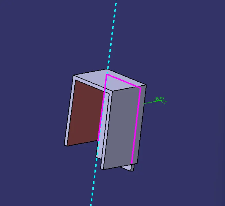
4 way locator
sketch palne over the same point using ZX plane as reference sketch on the plane. take a references from the master section lines then draw pluse like sketch. and then pad it in upward then give thickness of 1 mm . apply chamfer at the top edges. then add draft to ita along the tooling direction
then add it to the Doghouse with by Boolean Operation.
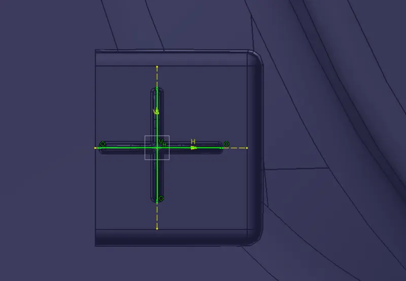
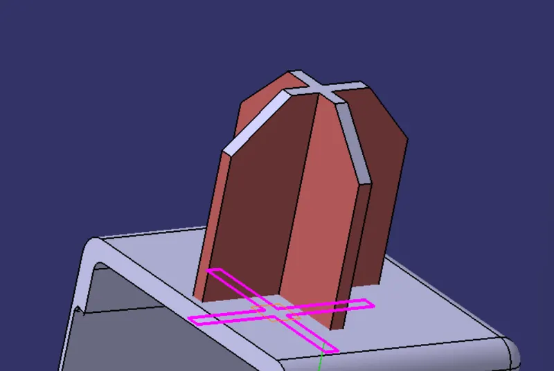
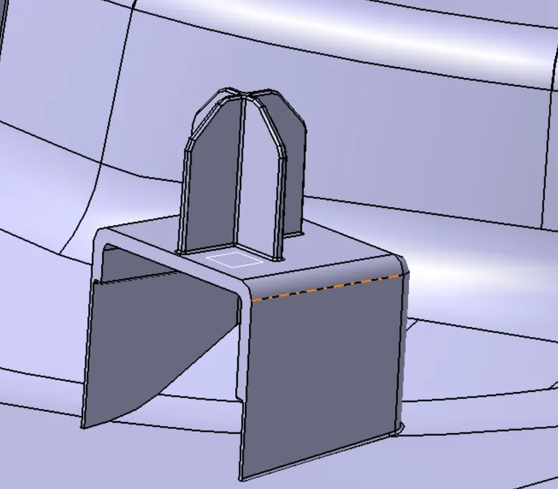
then mirror the doghouse loactor body to the other side and then trim it to the mian B pillar component as shown above.
Apply fillets.
Creation of RIBS
to create the rib sketch on the same plane wich we created for the 4 way locator, sketch on it give the distance btween ribs 50mm as per the design rule.
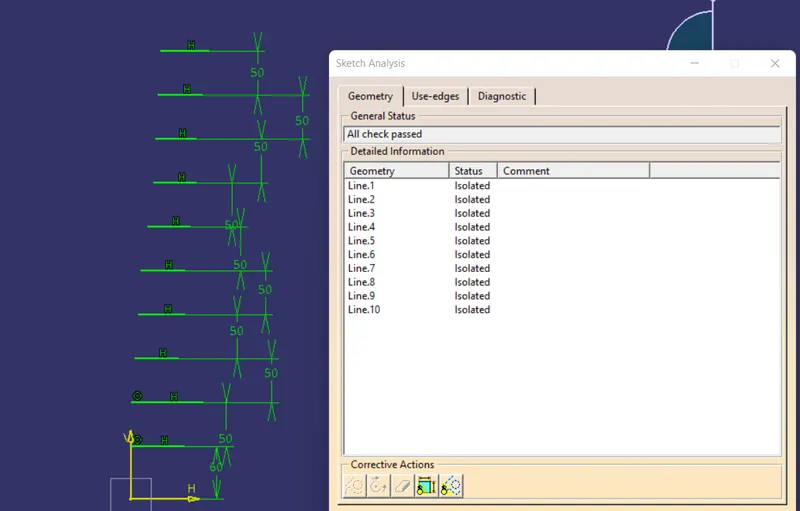
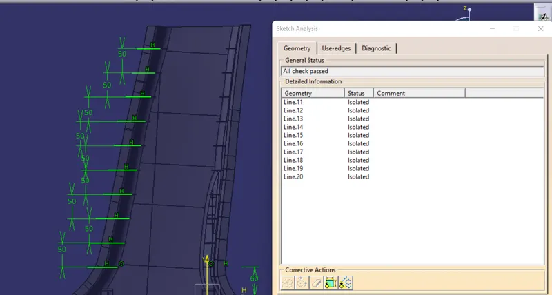
then extrude extract thes lines one by one and extrude them by appropriate hight then thicken theme by 0.8 mm as the design rule for the rib. i.e 0.4 % of the main coponent thickness.
then split them by class B surface then. offset the class B surface 10mm upward and then split again with this offseted surface. hight of the rib should be 5 times of thickness of the component.
then use boolean operation and use the and union trim with the main component
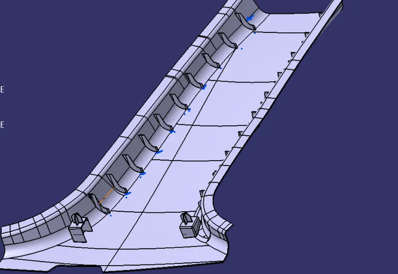
final component
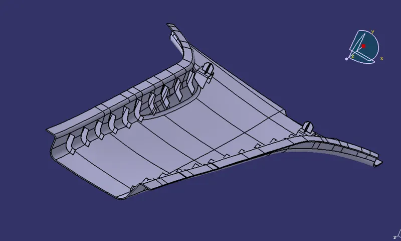
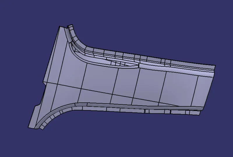
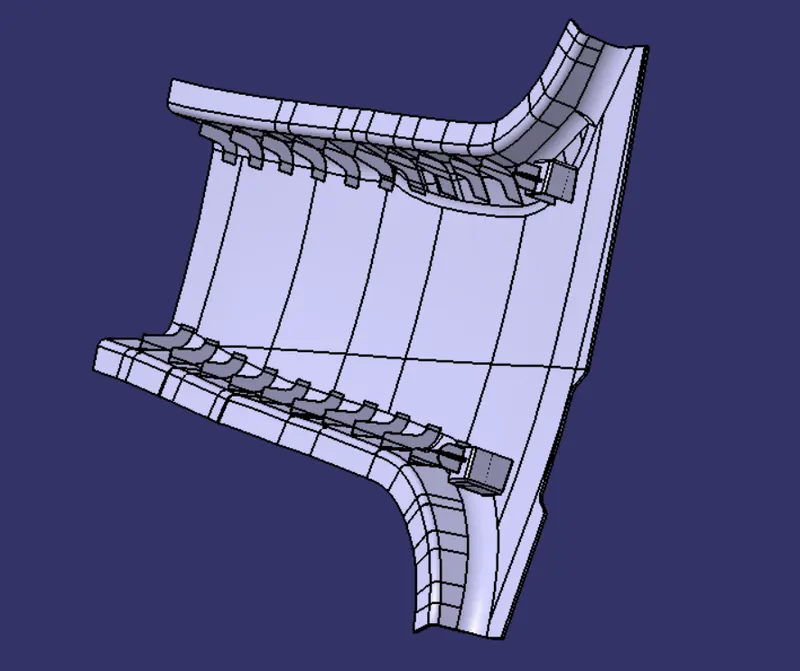
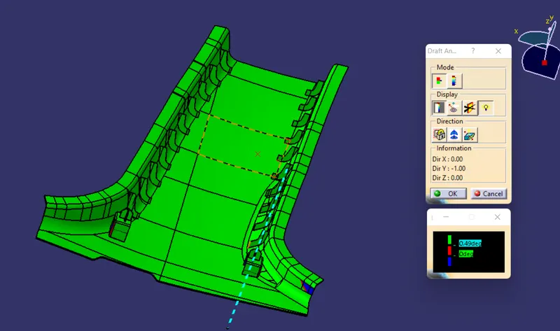
component draft
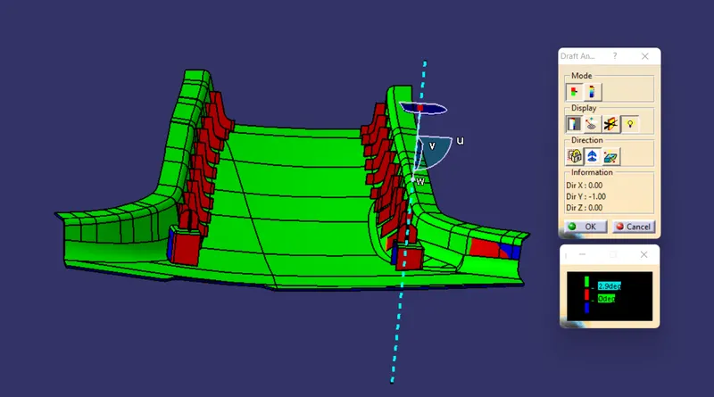
so here the ribes faces showing red because of the minimum angle present at the ribe faces are 0.5 degree.
it will clear if we appy 0.5 degree.
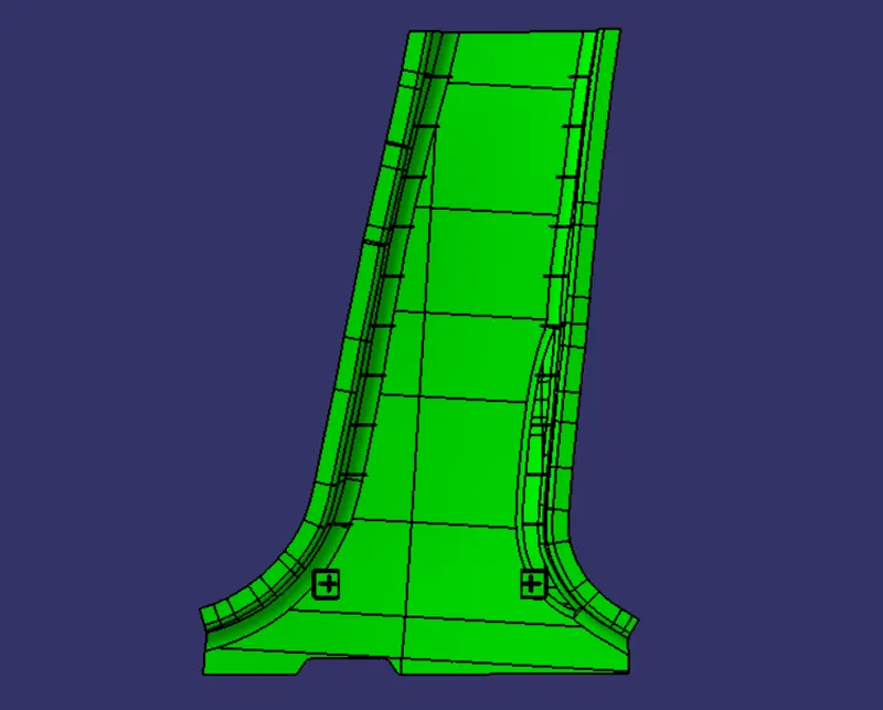
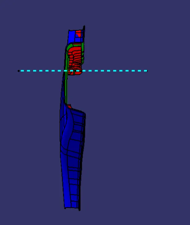
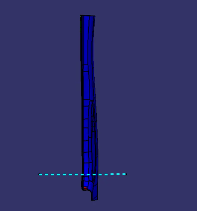
so here is when applied 0.5 degree for the ribes
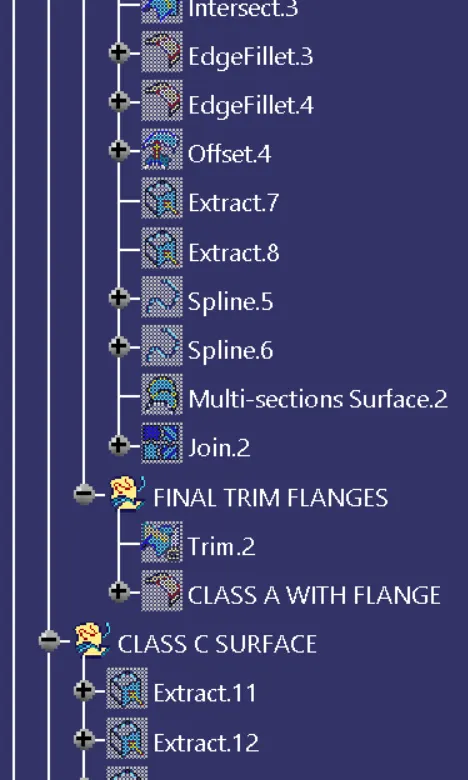
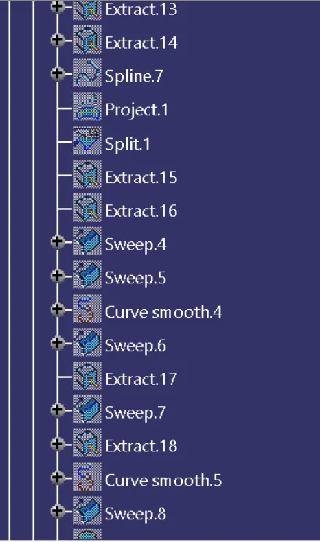
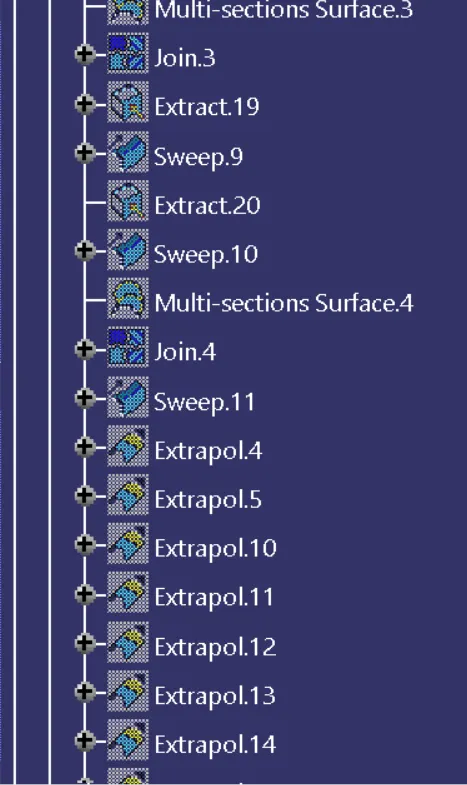
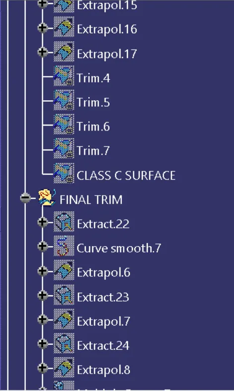
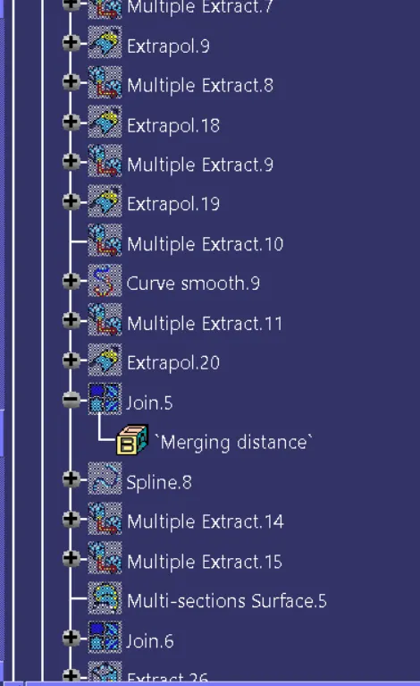
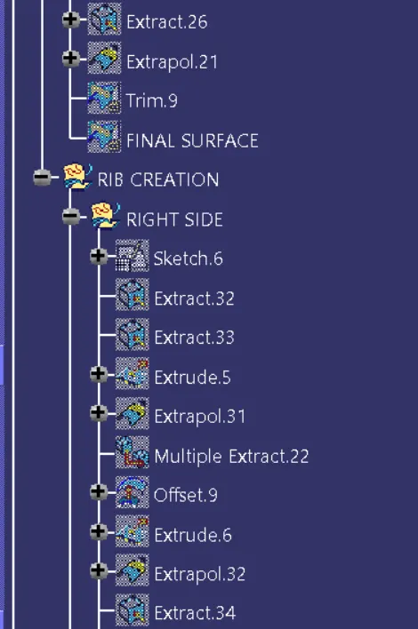
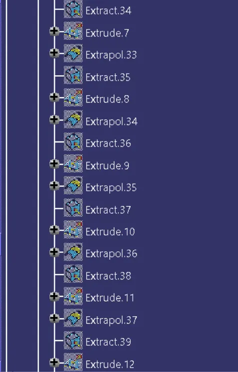
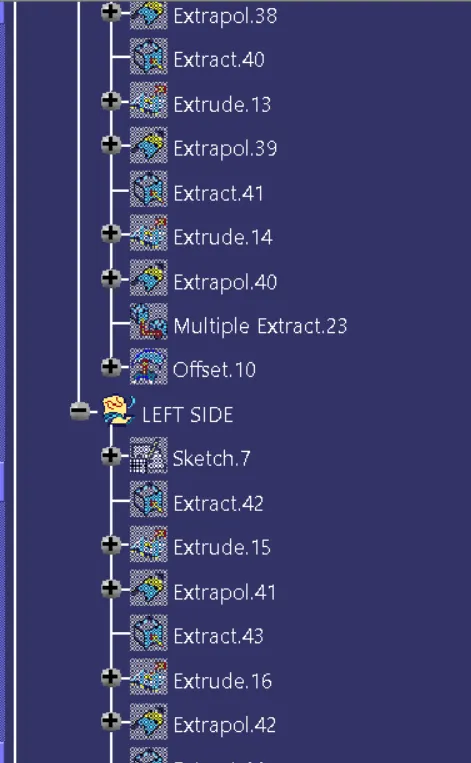
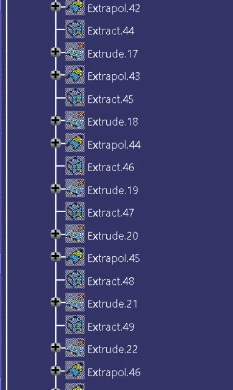
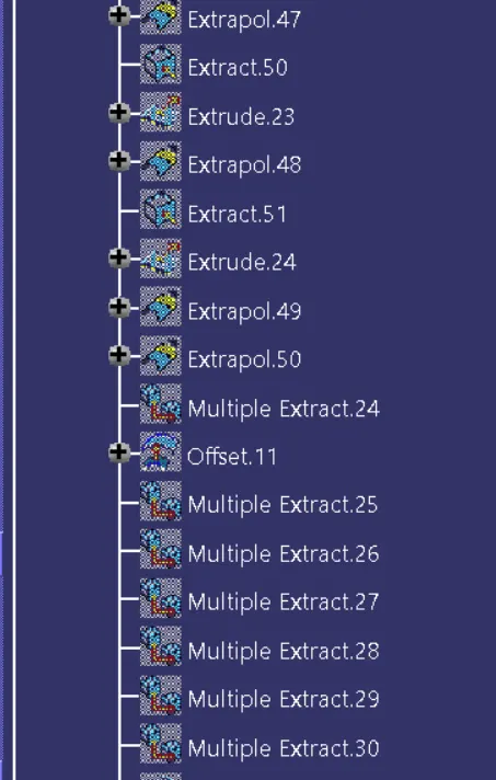
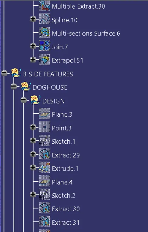
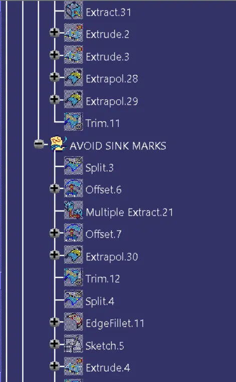
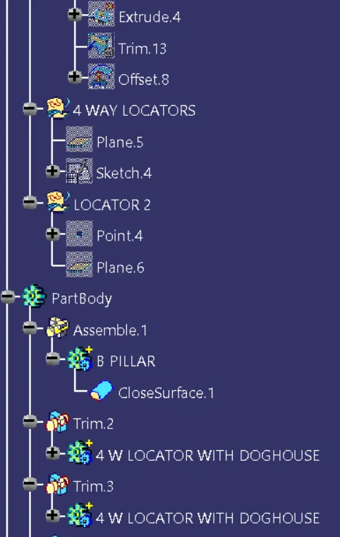
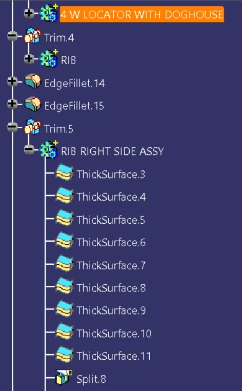
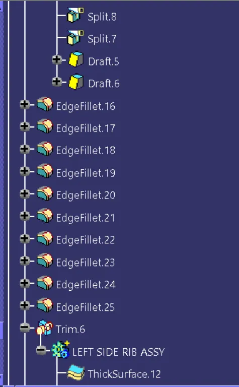
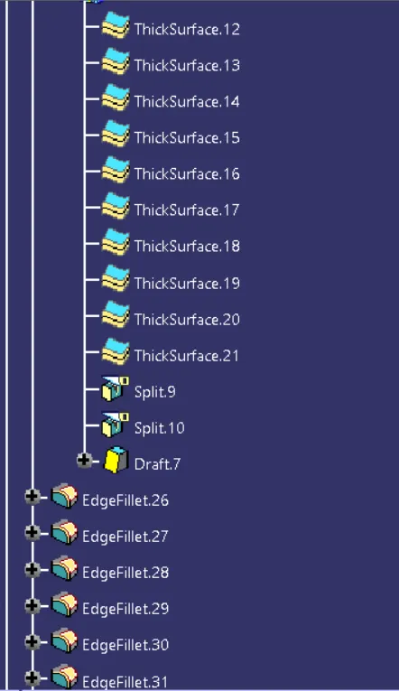
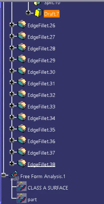
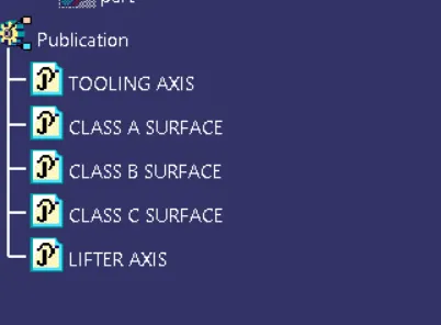
TREE STRUCTURE