Week 10- Assembly Workbench
QUICK RETURN MECHANINSM
PART 1
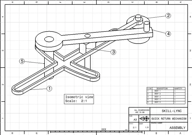
In this part we created 5 sub parts which assembled togather to form this Quick return mechanism.
BODY 1
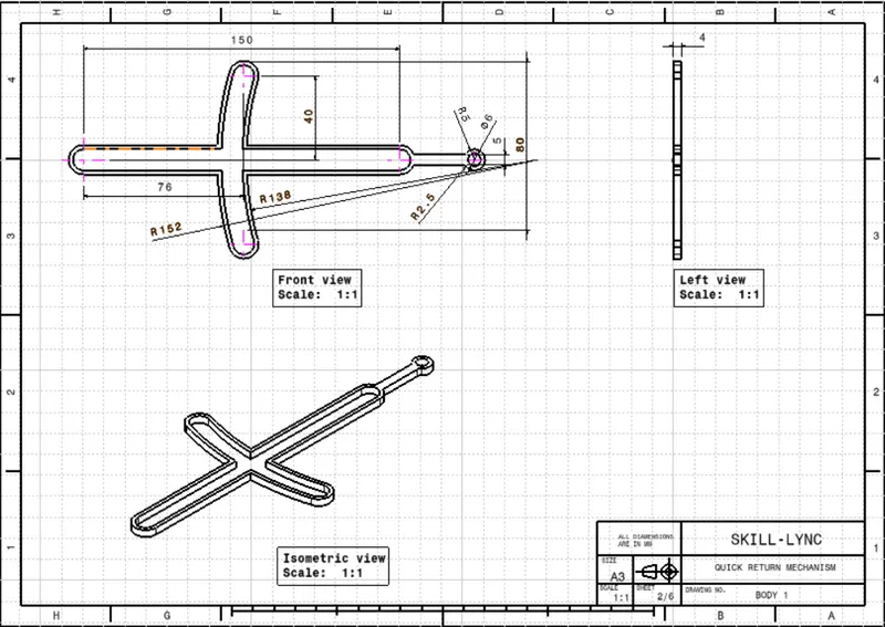
this part is a base body where the reamining part is going to rest, created this part with a single sketch and a pad.
created a sketch at the center of the all planes which is going to be a reference point while assembly.
BODY 2
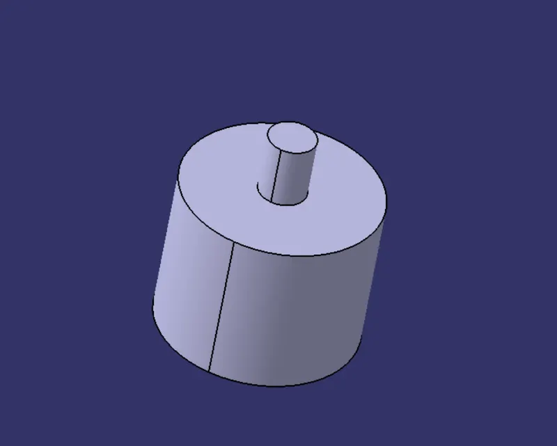
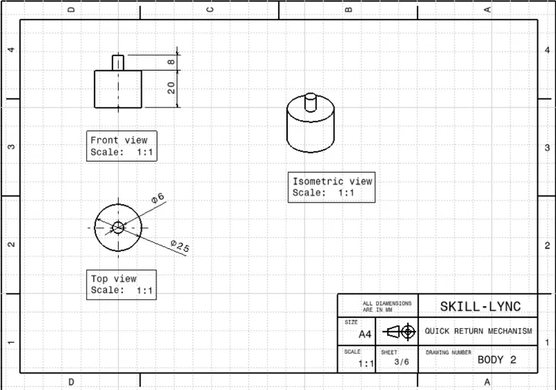
to create Body to i draw a circle of dia 25mm at the origine on the XY palne then pad it in upward direction for 20mm, then again draw a circle of dia 6mm on the upper face of the pades surface and drawed the circle at the origine. then pad it for 8mm.
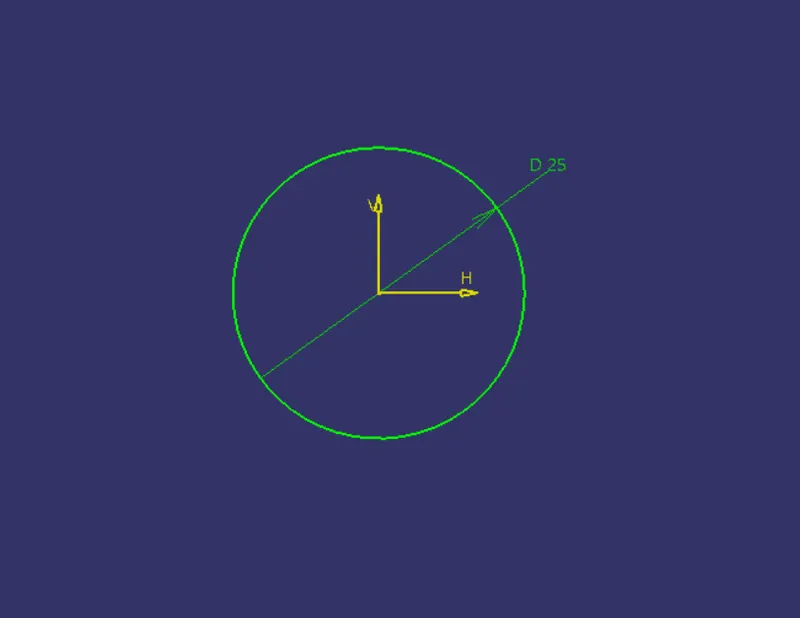
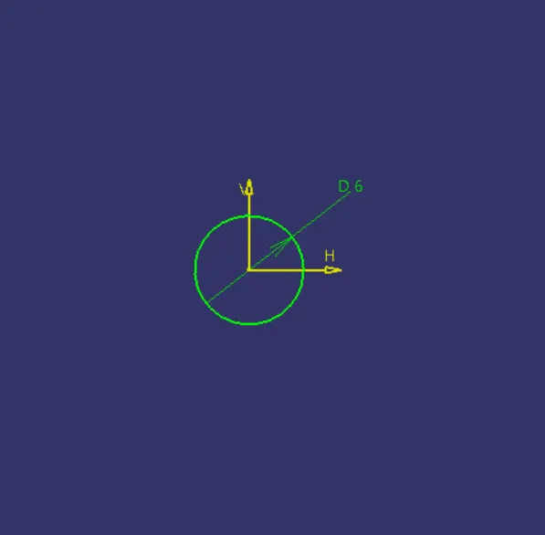
sketch 1 sketch 2
BODY 3
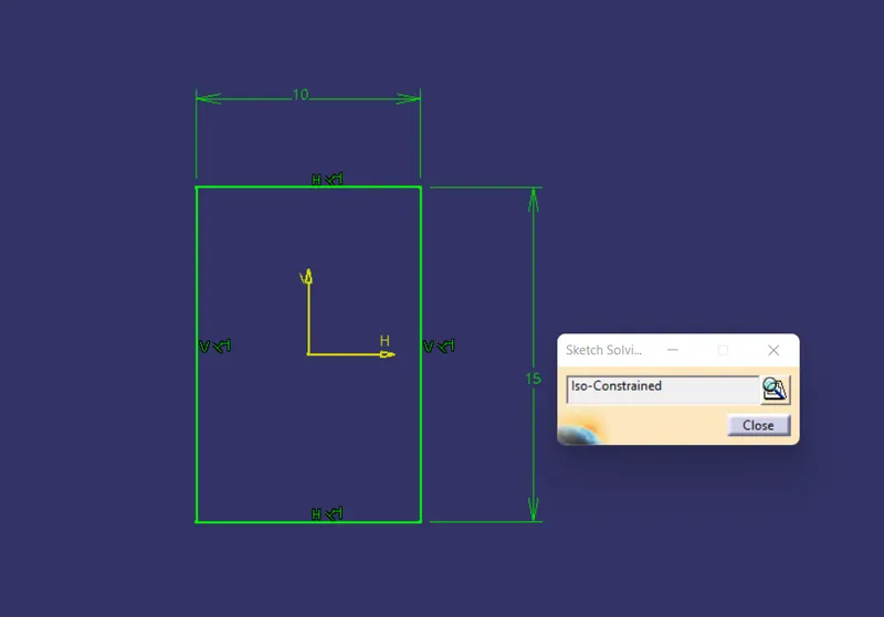
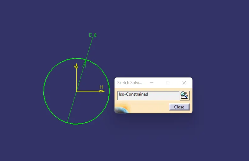
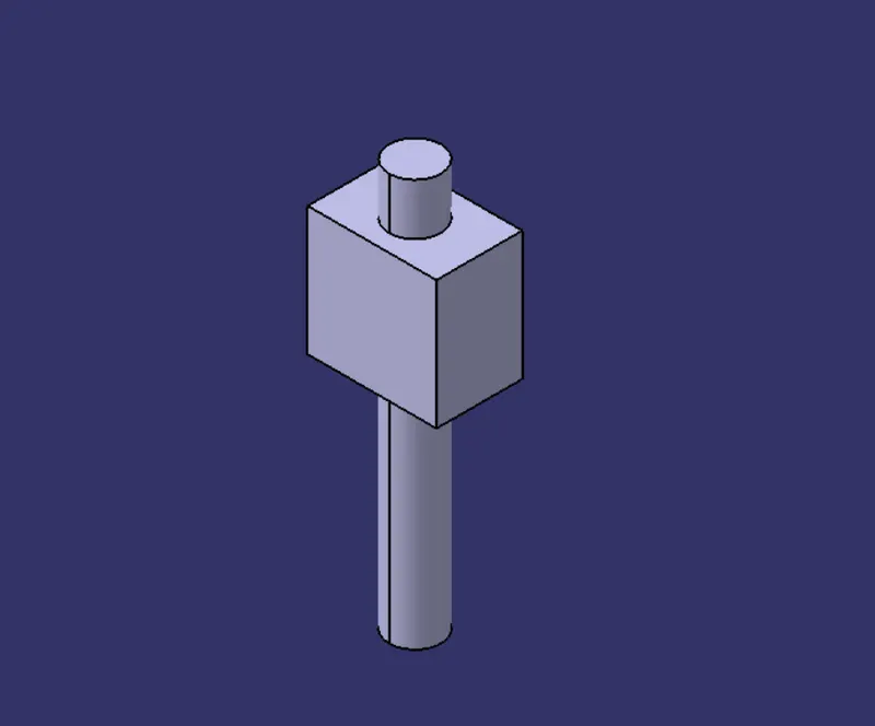
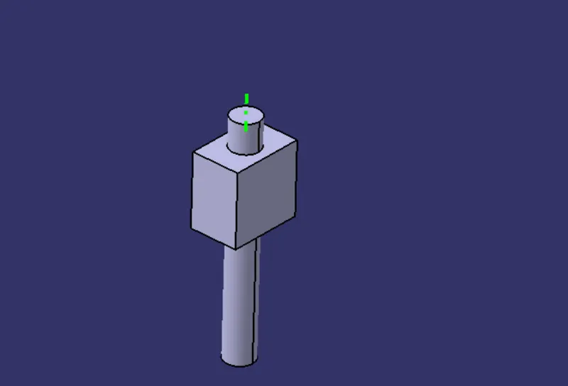
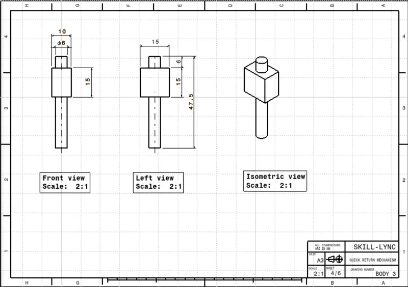
TO create Body 3 i have drawn on xy plane drew centeral retangle of 15 by 10 from the origin. then pad it for 15 mm. then again drawn over the xy plane and drew a circle of dia 6mm and pad it for 21mm in upward and 26.5mm in downward.
BODY 4
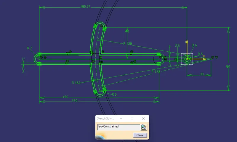
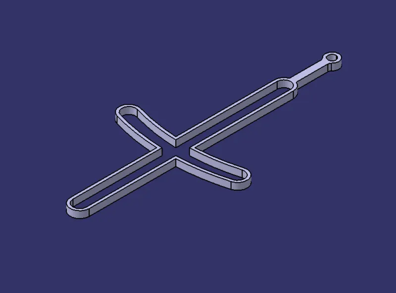
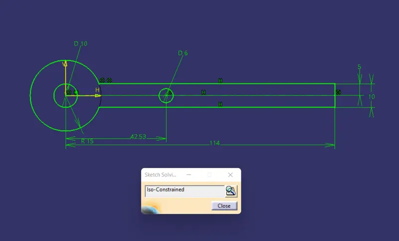
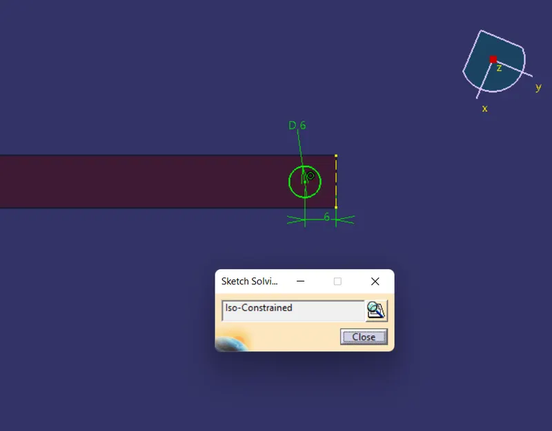
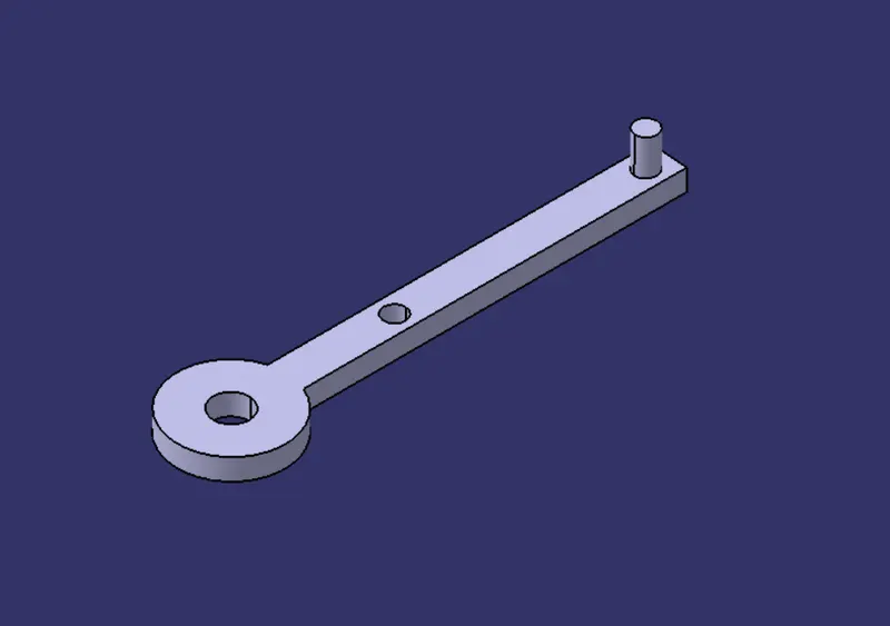
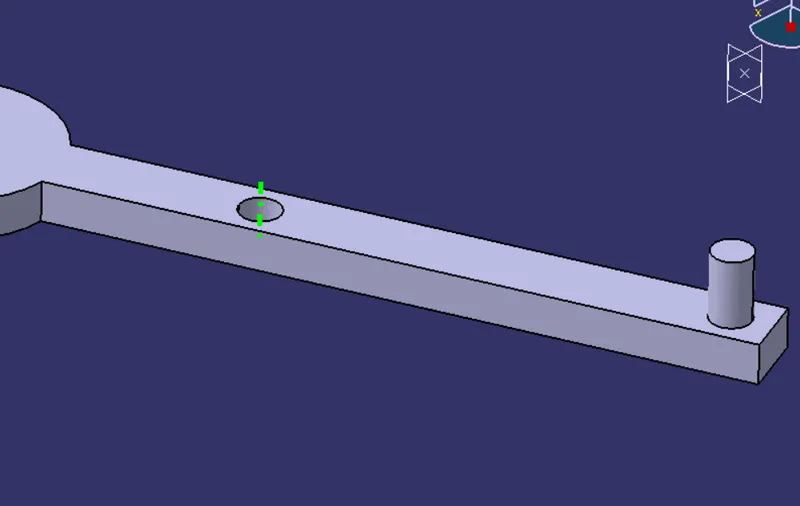
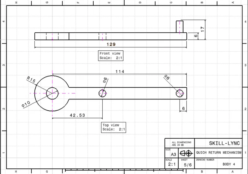
To create body 4 drwa sketch on the xy plane, draw two circles at the origine of 10mm dia and 25mm radiaus then a verticle line to right at distance of 114mm. then drawn two horizontal lines at 5mm each up and down of the horizontal line, thes two lines should intersect the outer circle and the vertcle line at the right. then trim the linr to get the disired shape, have drawn circle of 6mm dia 42.53mm to the right coinsides with the horizontal.pad it for 6mm then draw a circle of 6 mm the right side of the present geometry. pad it for 10mm.
BODY 5
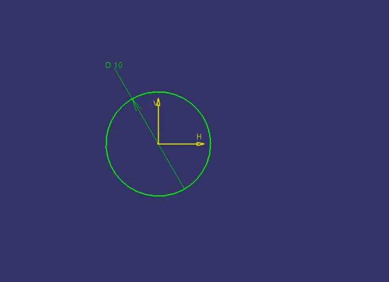
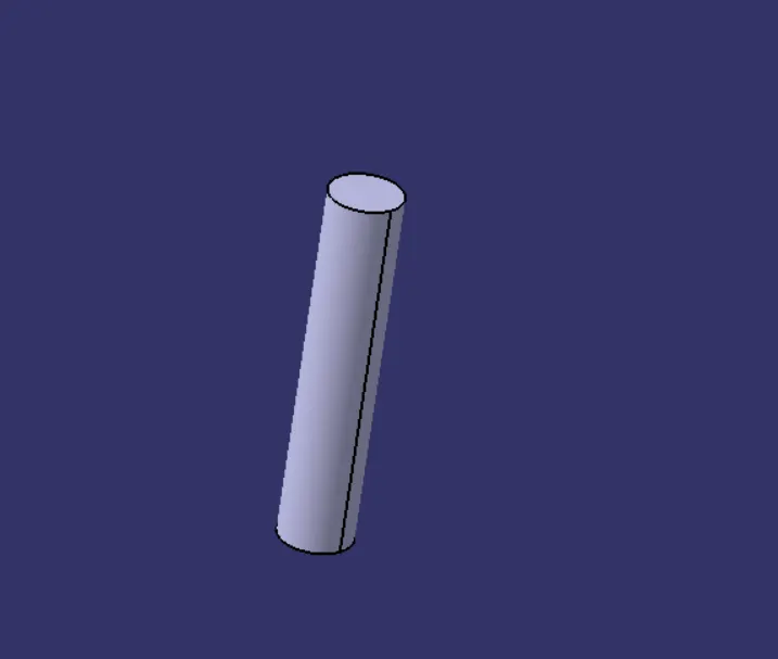
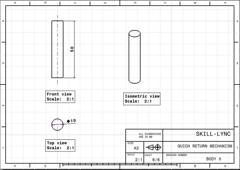
TO create body 5, sketch on xy plane draw circle of 10mm dia at the origin and pad it for 50mm in downside.
ASSEMBLY
Now all part are crate, asseble them togethor to make the complete part now.
the Qiuck return Mechanism id going to be a relative motion mechanism so we have to give the constaints with respect to parts with each other.
Open assembly workbench. created a new part which have only the a center point named it reference point so its going to be a skeleton where all our bodies to be rest.
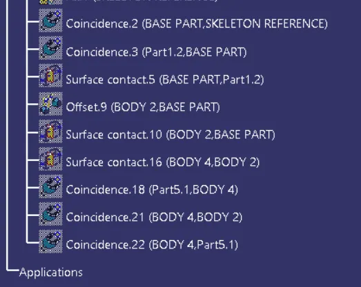
Insert Body one by using existing component command then using coincident constraint select the both reference points.
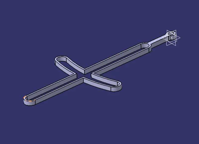
now insert the body 2 in to the assembly, then we crated a axis at the hole of the body one and at the center of the body 2. then applied coincident constraint to the both axis. then applied coincident constraint down side face of the body 1 and the upside face of the boy 2 then update.
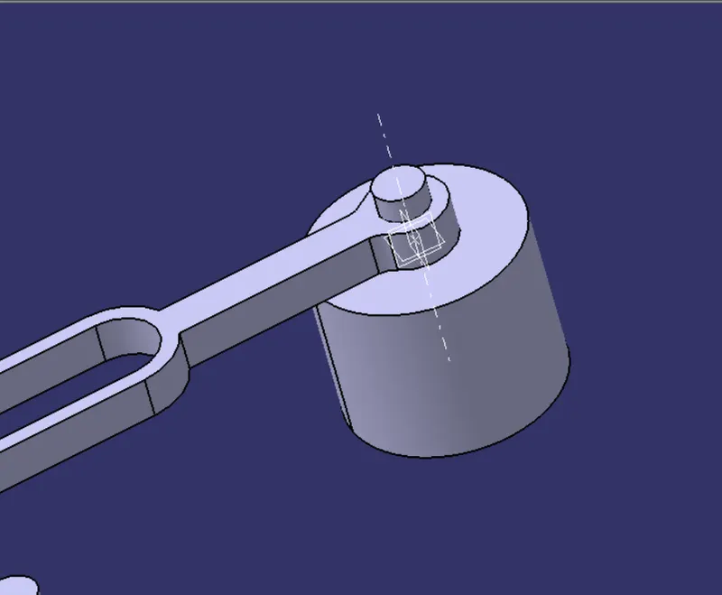
Insert Body 3
then give contact constraint to the highilghted faces of the body 1 and body 3.
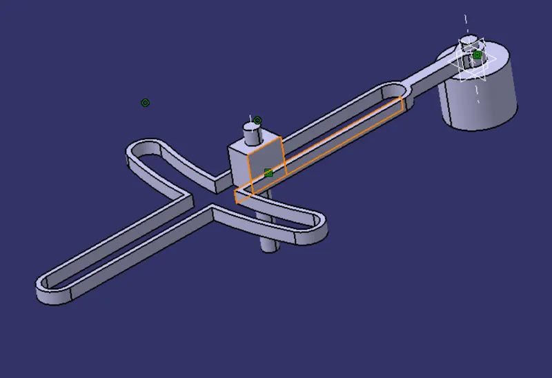
then applied a offsed constraint to the down side faces of the both 1 and 2 body faces. given offset is 0.
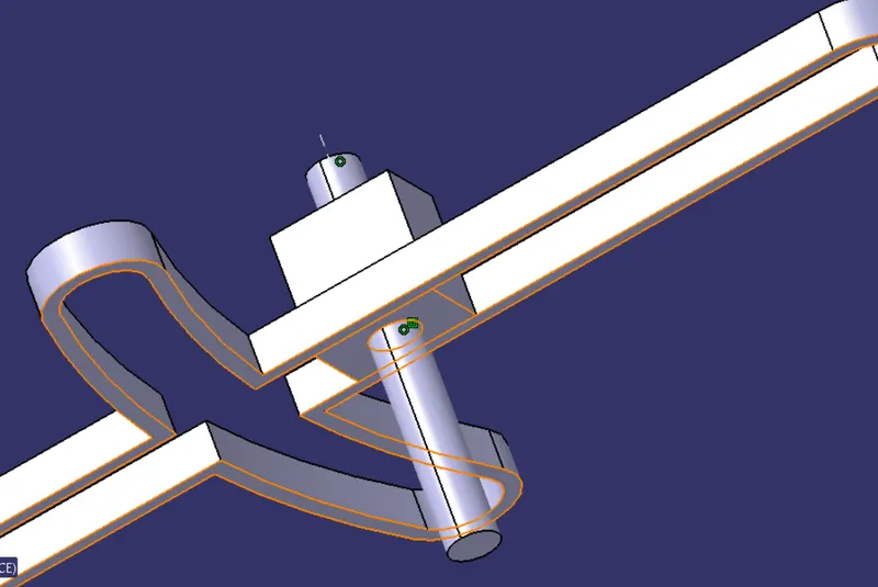
so the body 3 can move in only x direction with respect to Body 1.
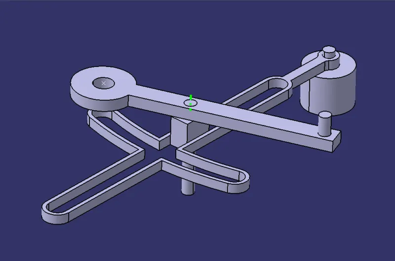
Now Body 4 inset the body 4
and then create reference axis to its samll hole and create a axis in the center of the body 3 as shown bellow. then coincide them using the coincident constraints.
the green colour line is the axis that i created.
Insert Body 5
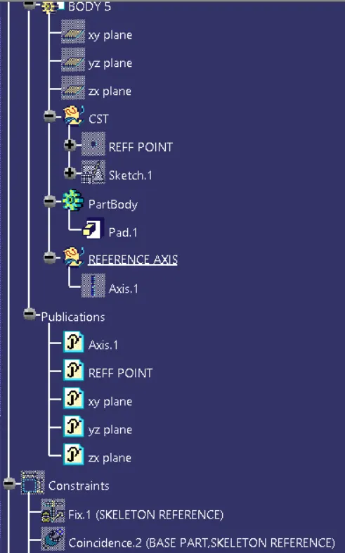
Now inserted body 5 in to the assembly and then created axis at the cneter of the body 5 and at hole of the body 4 as follows.
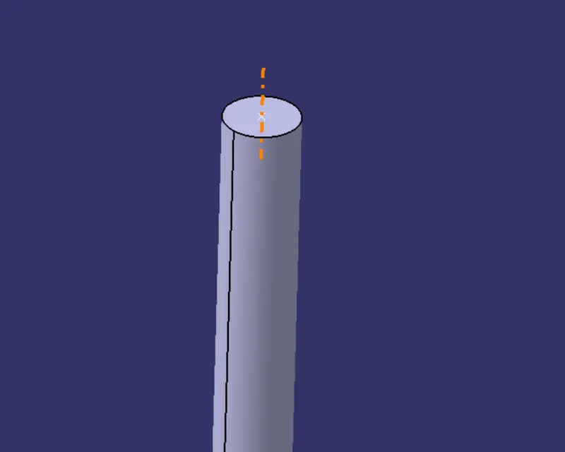
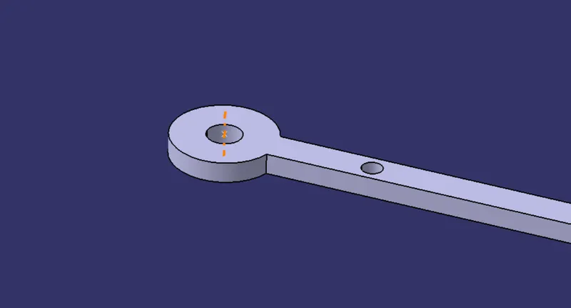
then applied coincident constraint to the both axis and coicidenet the axis, then again applied coincident to the rference points at the centr at the hole and at the top of the body 5 .
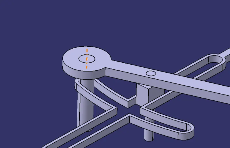
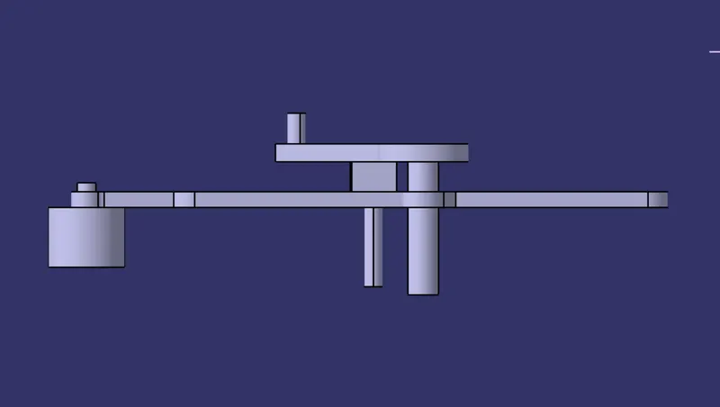
FRONT VIEW
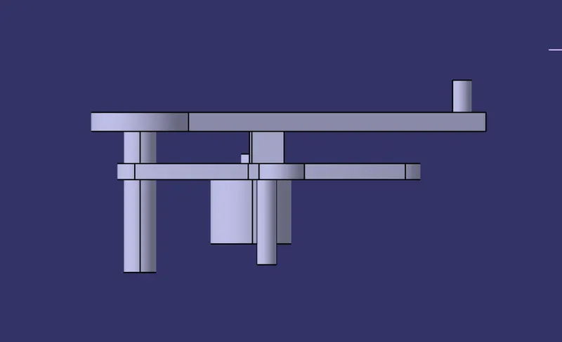
SIDE VIEW
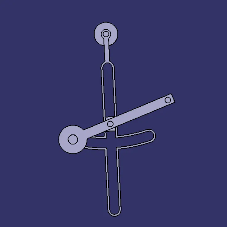
TOP VIEW
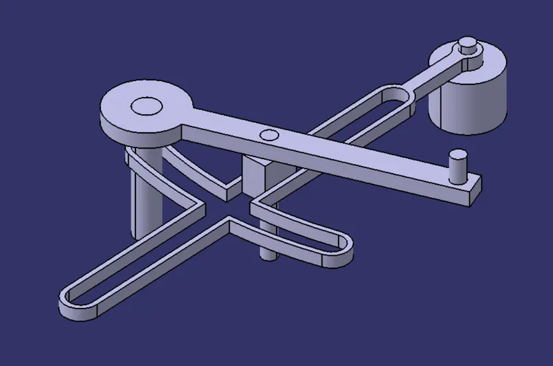
ISOMETRIC VIEW
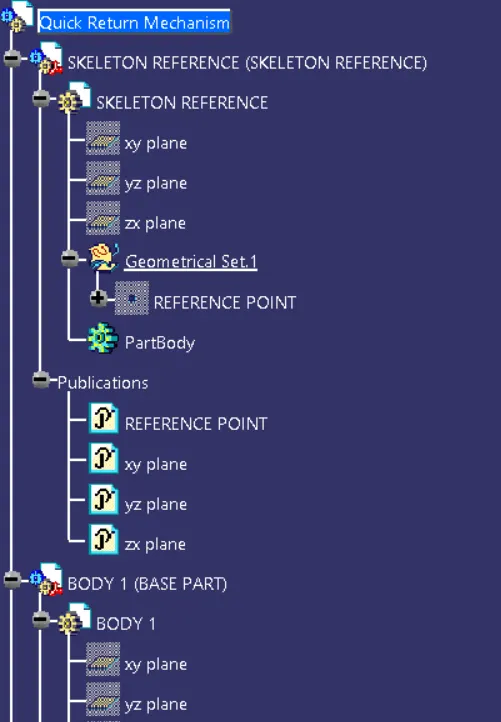
TREE STRUCTURE
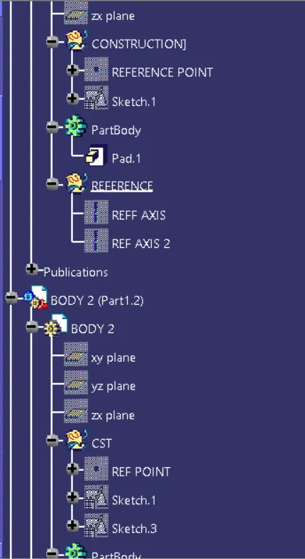
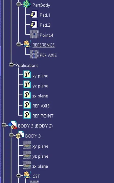
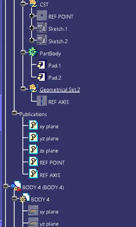
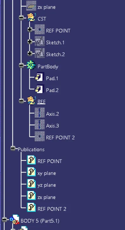
PART 2
DRAFTING
-------------- * * * -------------
CV JOINT
PART 1
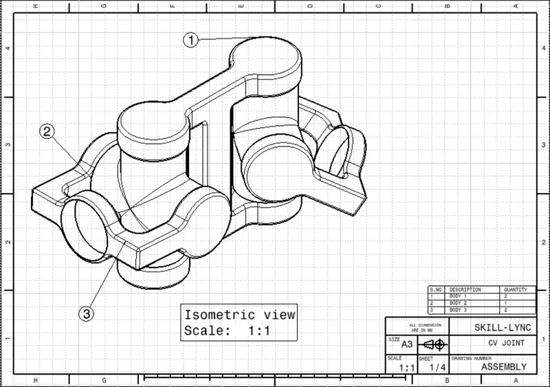
To create CV joint assembly. modled 3 Body individualy and assembled them in assembly to make a cv joint assembly.
BODY 1
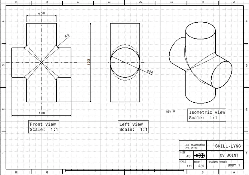
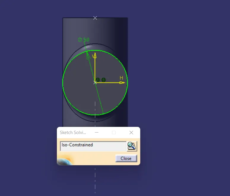
to create body 1 sketched on xy plane drawn a circle of 50mm dia at the origine. then pad for 50mm in with mirror extend so the total length of the pad is 100mm.
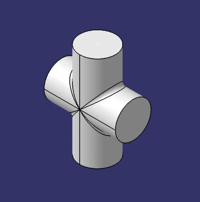
same way second pad is done but this time this pad is perpendicular with the first padand the both pad are intersecnting each other form their mid point making pluse like symbole.
then applied 5 mm of radius to its sholder area.
Body 2
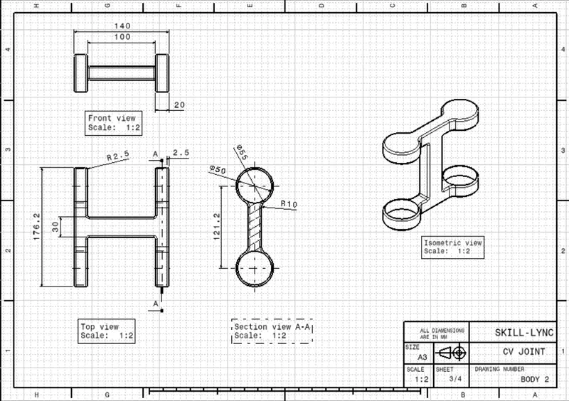
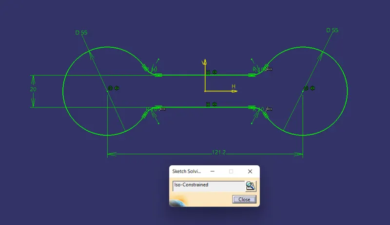
body 2 is going to a base of the cv joint, to create the it i have drew two circle of 55mm, 121.2 mm appart from each other centering origin between them.
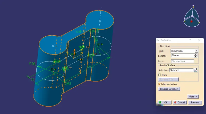
then two horizontal line 20mm apart centering origin between them intersecting both the circles then trim them to get the proper geametry as shown below and applhy fillets of 10mm at intersection area of line and cicles as shown. then pad it for 140 mm half up and half down.
then drawn cuting blocks for the to get the required shape for it.
for that sketch on zx plane and draw two rectangular as shown, then pad enogh so it could cut the body one in required shap.
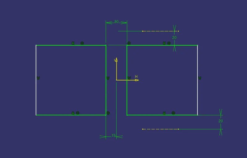
pad it in defferend body then remove the part from the body 1 using boolean operation.
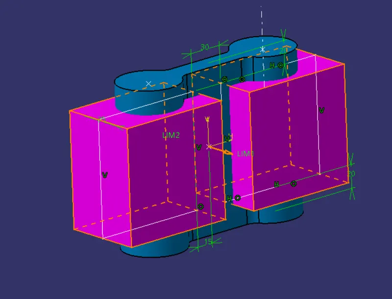
then created two cicle of 50 mm each at the center of the same cirlce we created for the main part. extrud them for 135mm. and remived them from the main part.
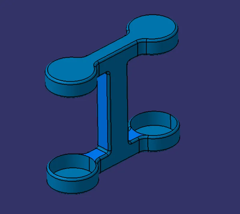
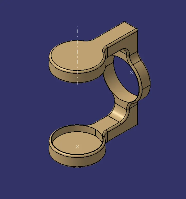
after that body 3 will the remaining, to create the body 3
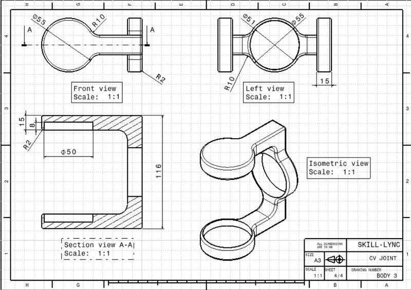
drawn sketch on the xy palne dran a circle of 55mm dia. 75mm left to the origin then dram horizontla line intersecting the circle.
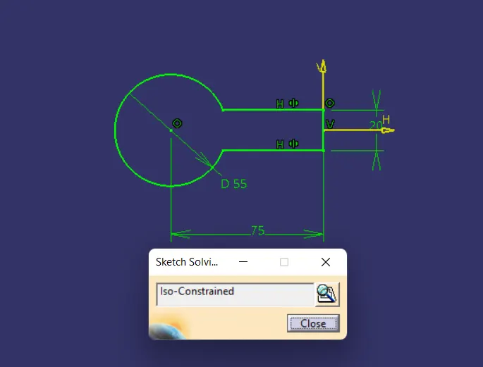
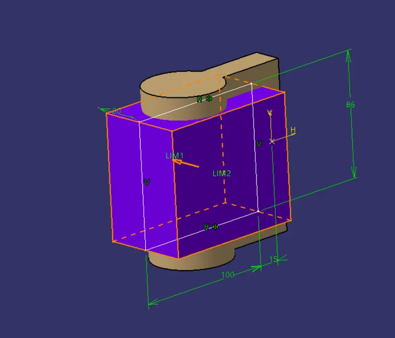
then drwan a cutting block to remove the unwanted part from the body to get the required shape.
then drawed a circle to remove the circuler part from the body. as shown bellow.
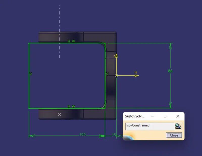
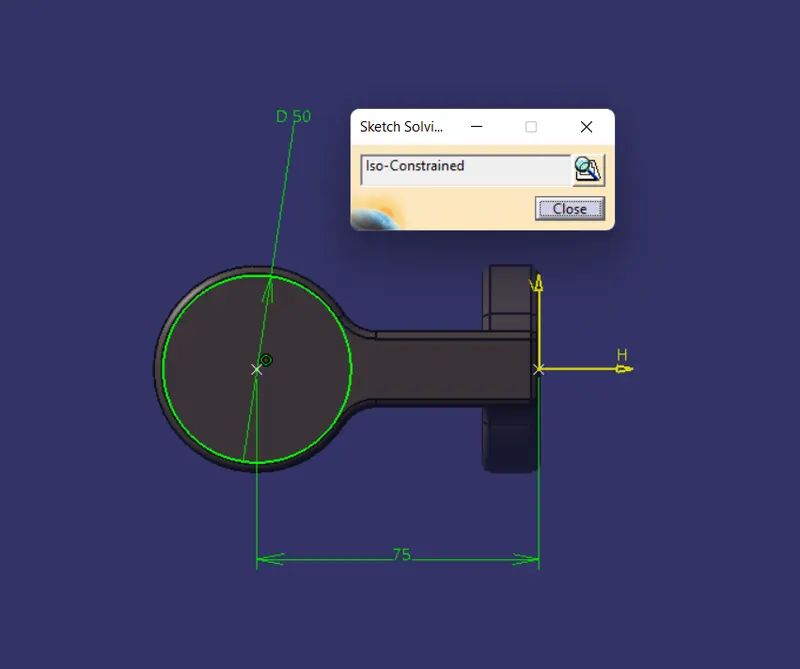
remove thes thes rectangular block and circular block by boolean operation.
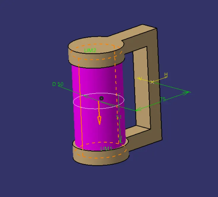
then apply fillet of 2 filler to the sharp edes
and 10mm fillet to the its adjesent adjes. to get the required shape
ASSEMBLY
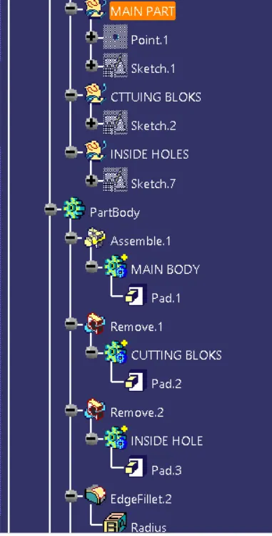
to assembly them go to the assembly workbench the created a part create cemter pont name it as a reference point, and name the part as a skeltone.then fic the thes part all our bodies is going to rest wrt this refference point. then insert the first body. body 2 is going to be the base body so i inserted it firt then apply coincident constraint to the bidy and refference point.
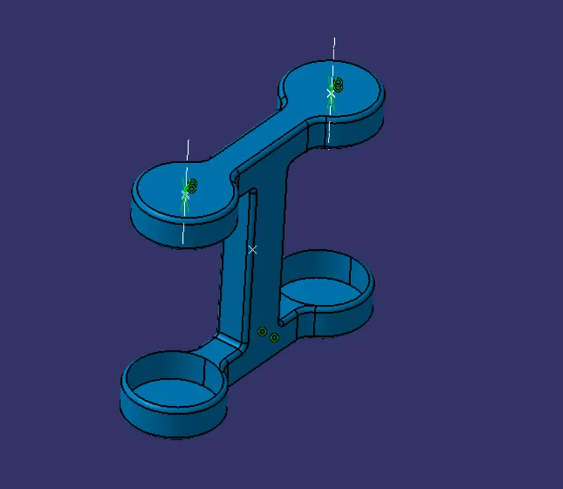
then insert the second body by existinng component command, the create a refferende axis for both base and the body. then coincide them to each othe. the using contanct constraint.

then uing the fast multi instantiation create the copy of of the second body and same as befor created axis at the center of the second part and the at other side circle of the base part. then concides them then added a offset constraint to to place it at the right place.
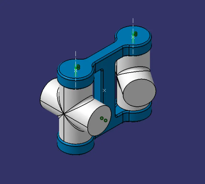
them isert boy 3 and created reference axis to its horizontal circular are and to the center of the second part as shown below
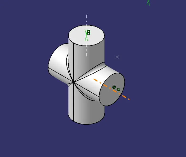
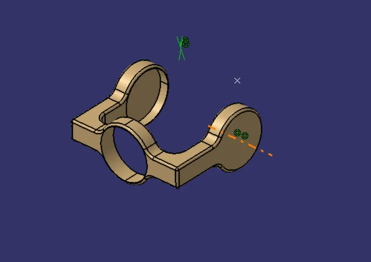
the concides thes two axis by coincident constraint. the add a offset of 1mm to the both inner horizontal faces of the both bodies
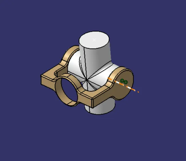
then same as befor for the body to create a cppy of body 3 by fast multi instantiation and do the same procedure as above did for this parts.
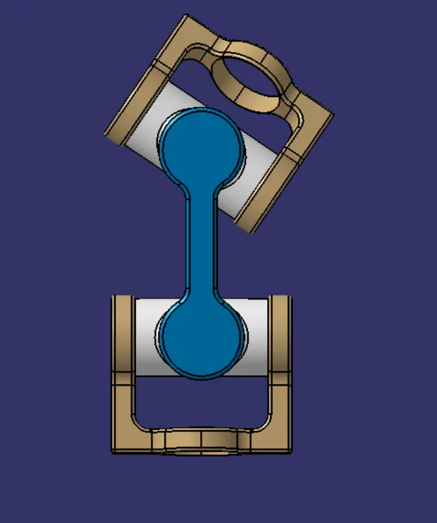
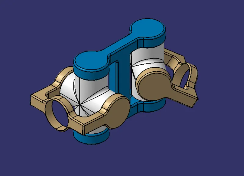
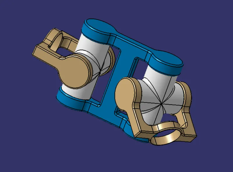
here is the final assembly of the CV joint
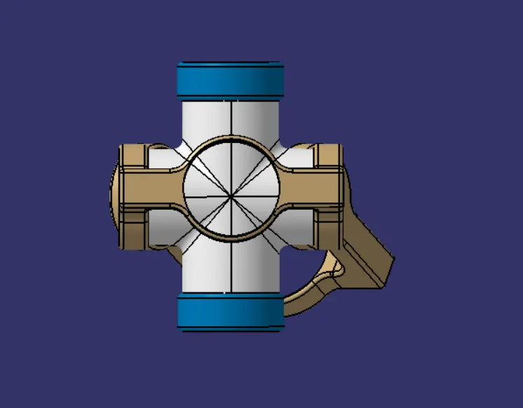
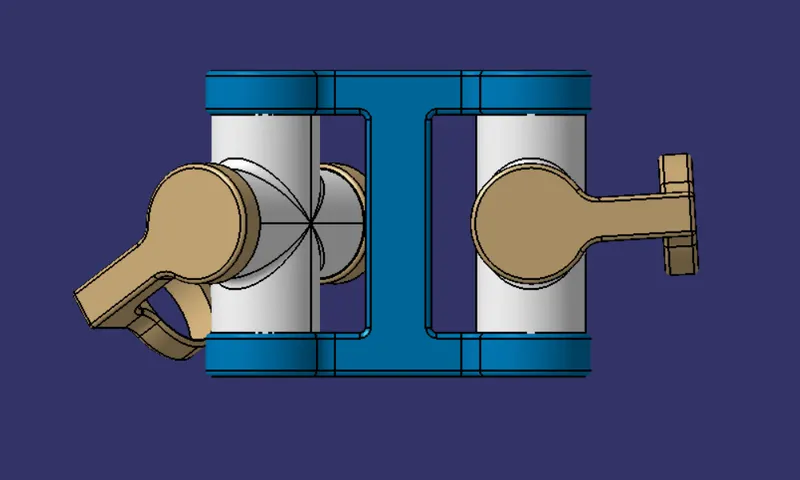
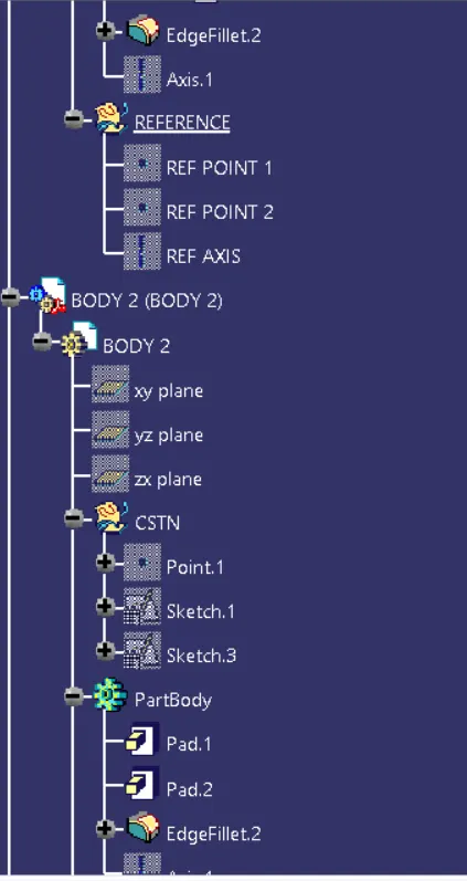
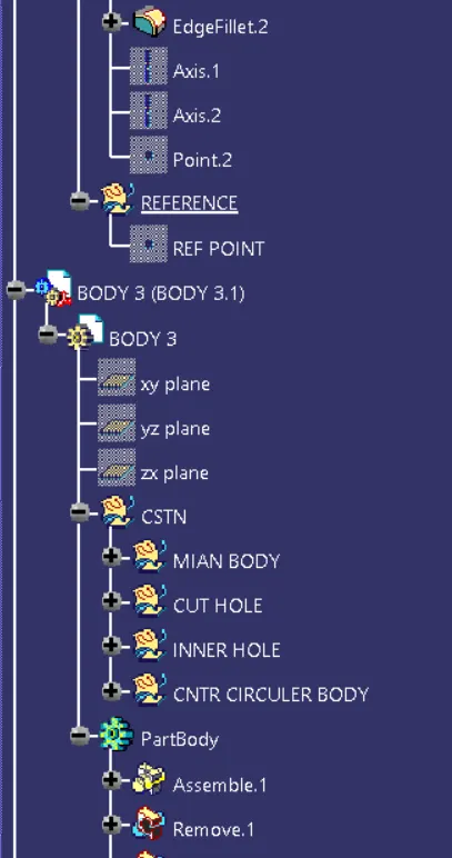
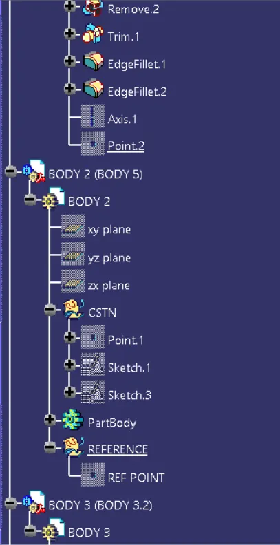
TREE STRUCTURE
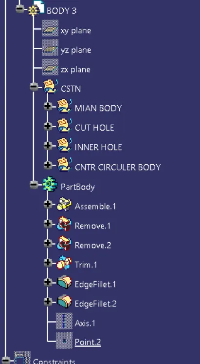
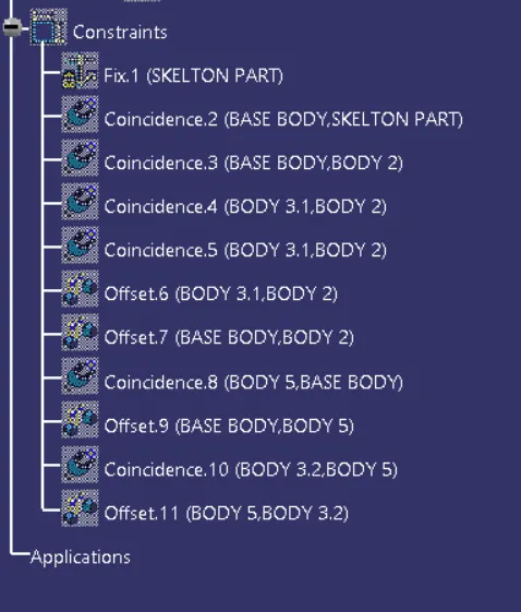
PART 2
DRAFTING