Meshing on the suspension Assembly of a Passenger Car Vehicle
Aim: To perform Tetra and Shell Meshing on the suspension assembly of a passenger car vehicle in the ANSA Interface.
Objective: The objective of this project is to perform meshing on the suspension assembly component. The Components having below 5 mm thickness should be captured with 2-d meshing and components having more than 5 mm thickness is to be followed with the volume mesh by following quality criteria and mesh the components with the respective parameters and to give the appropriate connections to the model in the end.
Theory:
The Finite Element Method (FEM) is a numerical approximation method, which investigates the behavior of complex structures by breaking it down into smaller, simpler pieces. These smaller pieces are called (finite) elements. The elements are connected to each other at nodes. These elements and nodes are also called meshes. The assembly of elements and nodes is called a finite element model.
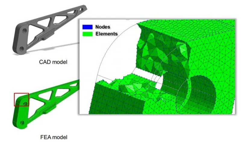
Different Mesh Types:
Mesh elements can be 1D, 2D, or 3D elements in the function of the model to simulate as in the below picture.
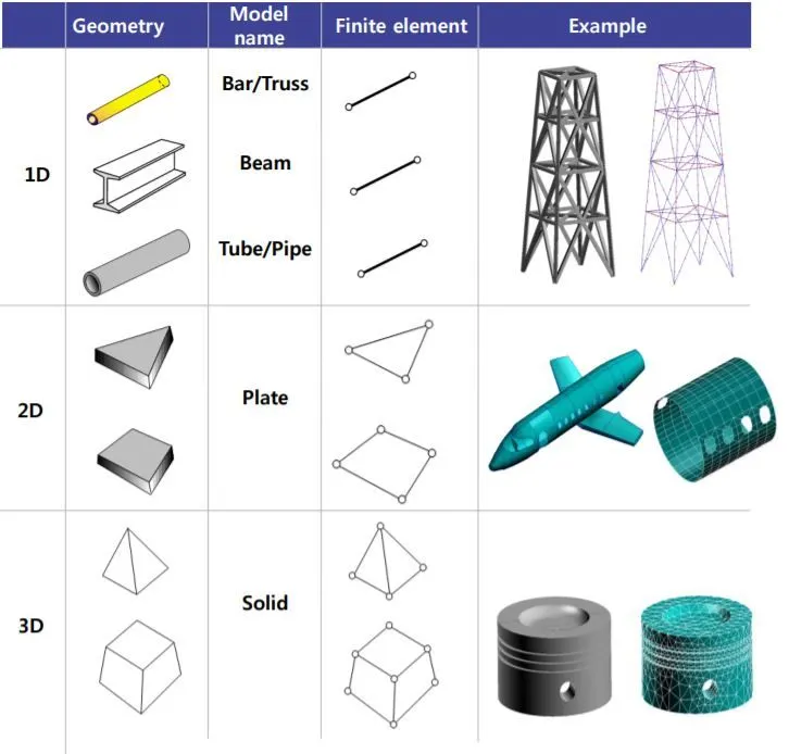
FEA model is always a 3-dimensional model, so if 1D or 2D elements are used, 1 or 2 dimensions need to be defined in order to be analyzed.
The below dimensions are defined by element properties.
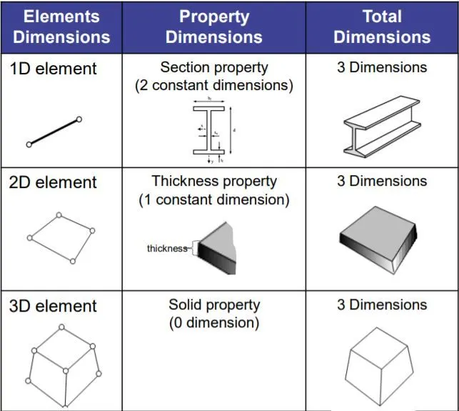
1D Element Properties:
1D elements are used when the length of the structure is 8-10 times greater than its width and thickness and when external loads are applied only to the joints.
There are 3 types of 1D elements:
- Rod element: only undertake compression
- Truss(bar) element: undertake tension and compression
- Beam element: undertake tension, compression, shear, and moment
2D Element Properties:
2D elements are used when the length and width of the structure are significantly larger than its thickness.
There are different types of 2D elements:
- Plate: general 2D element
- Membrane: no bending
- Surface: no thickness
- Plane strain: strain normal to the surface is 0
- Composite Shell: 2d plate elements with composite layers.
3D Element Properties:
3D element properties are only present to assign Materials and Material Coordinate Systems to 3D meshes.
3D Mesh Types:
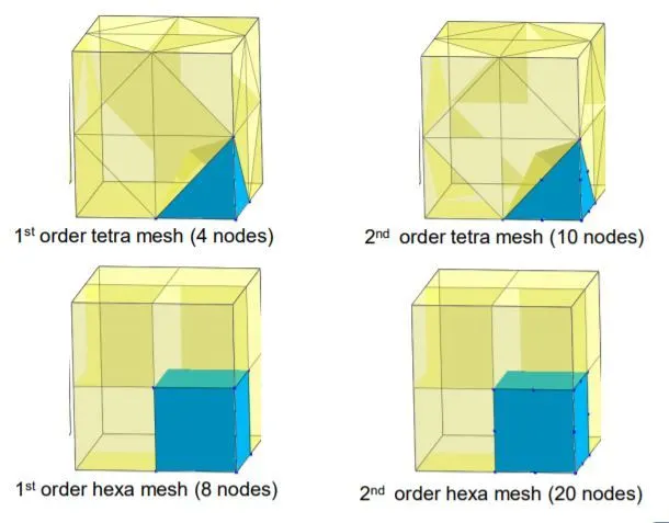
There are 2 main types of 3D elements, tetrahedral elements (4 faces, 4 nodes) and hexahedral elements (6 faces, 8 nodes).
2nd order elements, called also quadratic elements, add 1 middle node to each edge.
The calculation is more accurate for hexahedral elements than tetrahedral elements. And it’s more accurate for 2nd order elements because the approximation function will be quadratic instead of linear.
INTRODUCTION TO VEHICLE SUSPENSION SYSTEM:
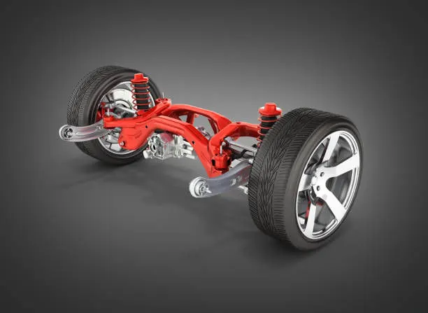
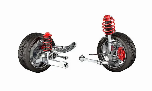
The automobile vehicle's frame and body are mounted on the front and rear axle not directly but through some form of springs and shock absorbers. This is done to damp to road shocks transmitted parts which perform this function are collectively called a suspension system.
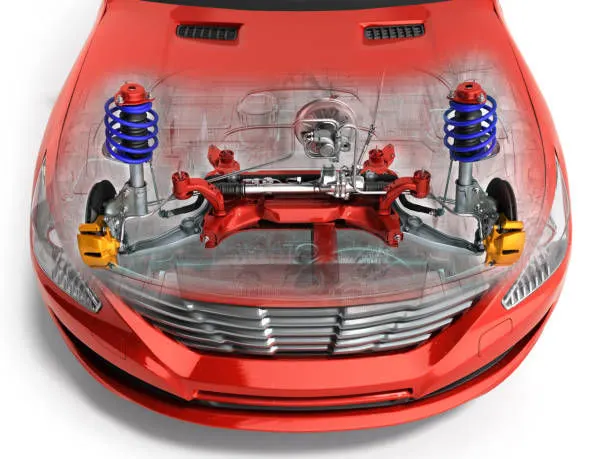
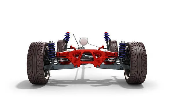
Thus, the suspension system includes springs, shock absorbers, and mountings. The suspension system of a motor vehicle is divided into the rear end suspension and front end suspension.
Types of Suspension System:
There are two types of suspension systems used in a vehicle.
- Front End Suspension System
- Rear End Suspension System
Front End Suspension System
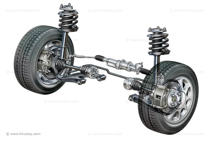
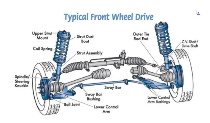
The front end suspension is more complicated than the rear end suspension because the front wheels not only move up and down with respect to the car frame but also swing at various angles to the car frame for steering.In order to permit the front wheels to swing to one side or the other for steering, each wheel is ported on a spindle which is part of the steering knuckle. The steering knuckle is then supported through ball joints, by upper and lower control arms which are attached to the car frame.
Rear End Suspension System
The most basic purposes of a suspension system are to prevent the body of a vehicle from hitting the ground and to keep the tires in contact with the road.
The rear suspension of a vehicle performs the same general function as front suspension, but the specific construction is typically quite different. The ideal suspension for a vehicle depends a lot on the vehicle's body style and performance requirements.
Rear-end suspension is of three types
1) Longitudinal leaf spring rear end suspension
2) Transverse leaf spring rear end suspension
3) Coil spring rear end suspension
Components used in a Suspension system:
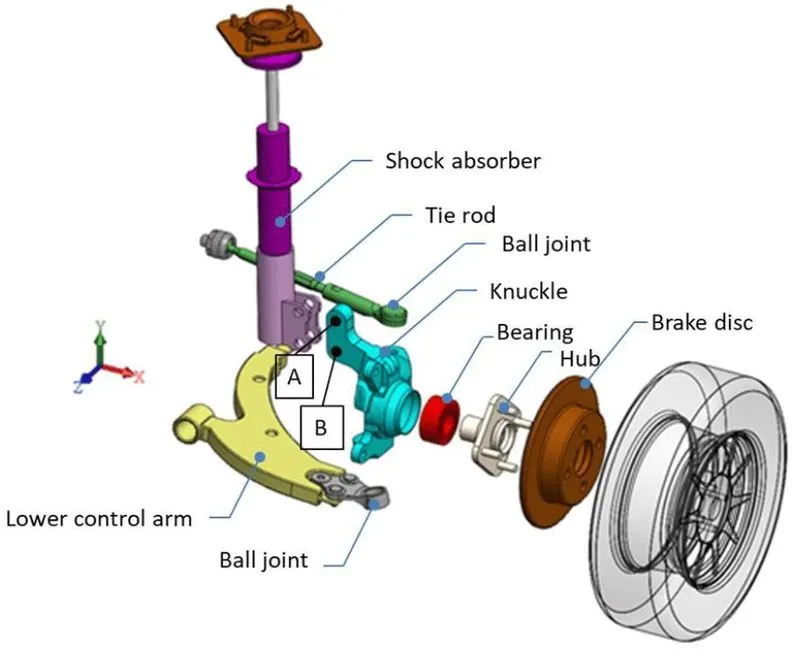
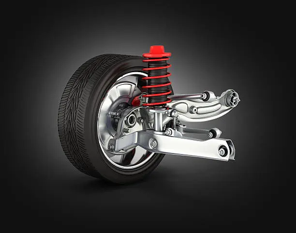
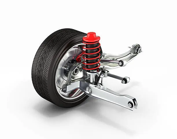
The suspension system consists of tires, the air in the tires, springs, shock absorbers, struts, arms, bars, linkages, bushings, and joints. The suspension system components are located between the frame of the vehicle and the road.
The suspension system in a vehicle consists of the following parts:
- These are the only part of the suspension system that touches the ground.
- Coil springs. These are the part that absorbs the impact when a vehicle hits a bump in the road.
- Shock absorbers. Sometimes called the shocks or dampers, this part supports the coil spring to further reduce the impact of a bump or pothole.
- Rods/linkages. These parts work together to link different parts of the suspension system together.
- Joints/bearings/bushings. These parts allow certain components of the suspension system to make sliding actions.
Some vehicles do not have shock absorbers. Instead, these vehicles come with struts. A strut is similar to a shock absorber, as it provides support for the suspension as well as the coil springs.
Functions of the Suspension System:
- To prevent the stability of the vehicle in pitching or rolling while in motion.
- To safeguard the occupants from road shocks.
- A suspension system prevents the road shocks from being transferred to the vehicle frame.
- To provide good road holding while driving, cornering, and braking.
- To maintain proper steering geometry.
Requirements of a Suspension system:
- Minimum deflection is consistent with the required stability.
- Comparability with other vehicle components-type, frame wheelbase, steering linkage.
- Minimum wheel hop.
- Low maintenance and operating costs.
- Low initial cost.
- Minimum weight minimum wear.
Procedure:
Import of the Geometry in the ANSA Interface:
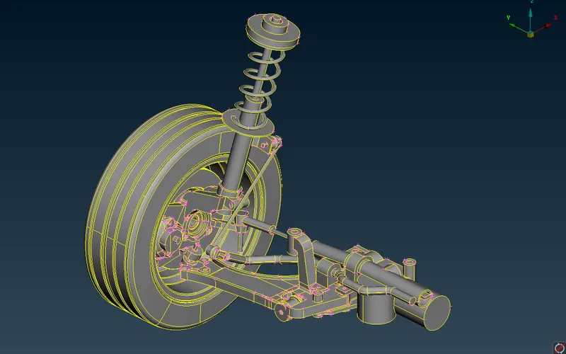
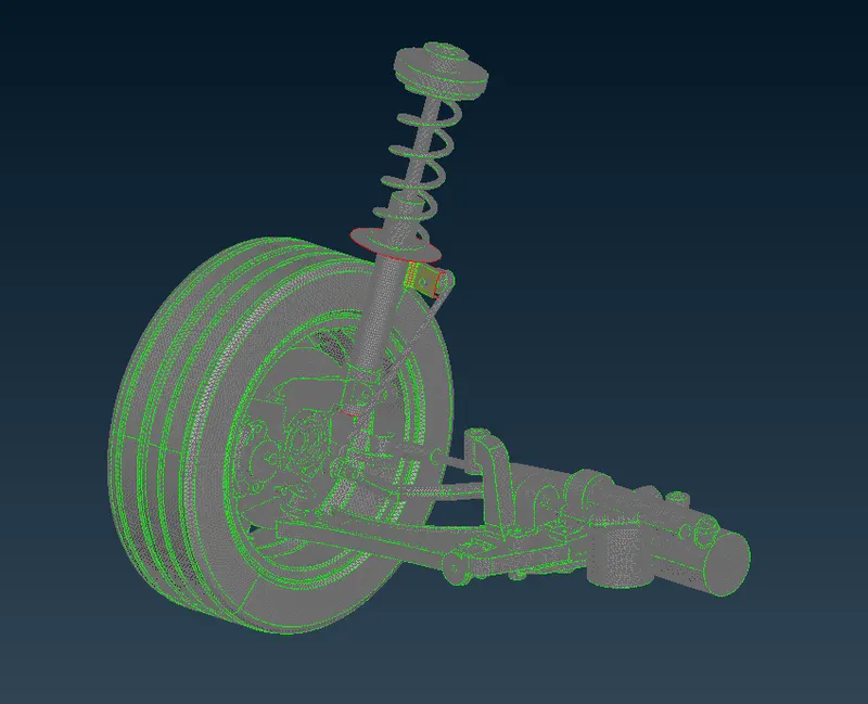
The above picture represents the imported CAD Geometry of the Suspension system of the passenger car vehicle. In order to check the geometrical errors. We first perform Topological cleanup and then proceed for the geometrical errors for better accuracy.
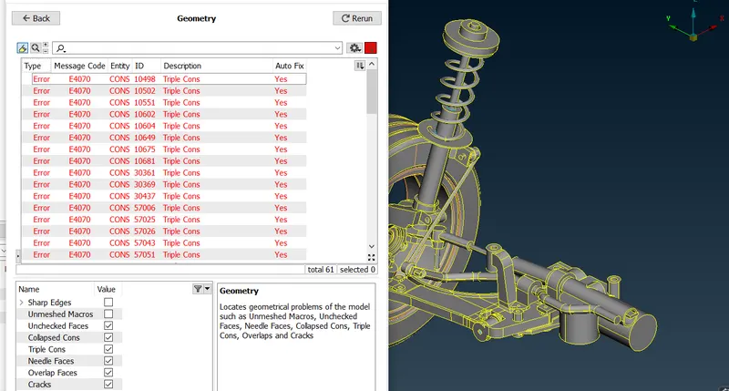
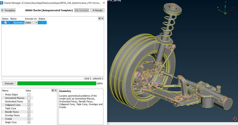
Here from the above pictures, we see that there were geometrical errors that are listed in the 1st picture. whereas in the 2nd picture we have fixed the geometrical errors and set to perform mesh on the component.
In order to perform mesh, it is always recommended to set the sub-components of a component in different PIDs with their respective properties.
Splitting the Components into Different PIDs

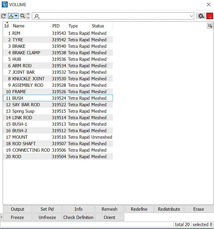
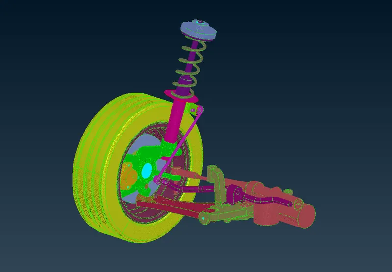
The above picture represents the property card created for the suspension assembly system.
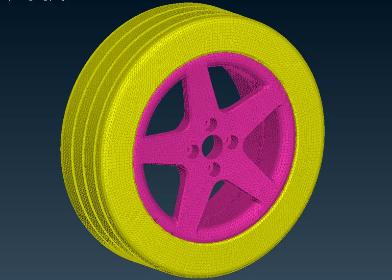
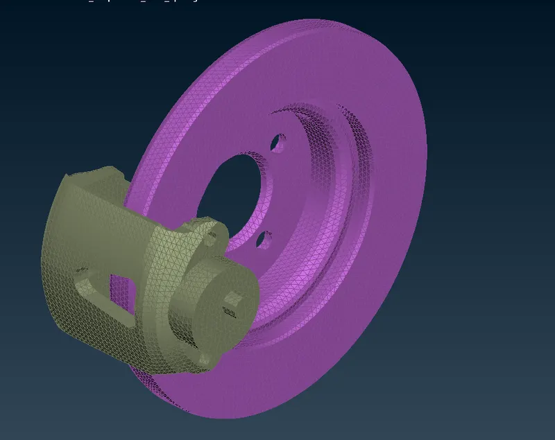
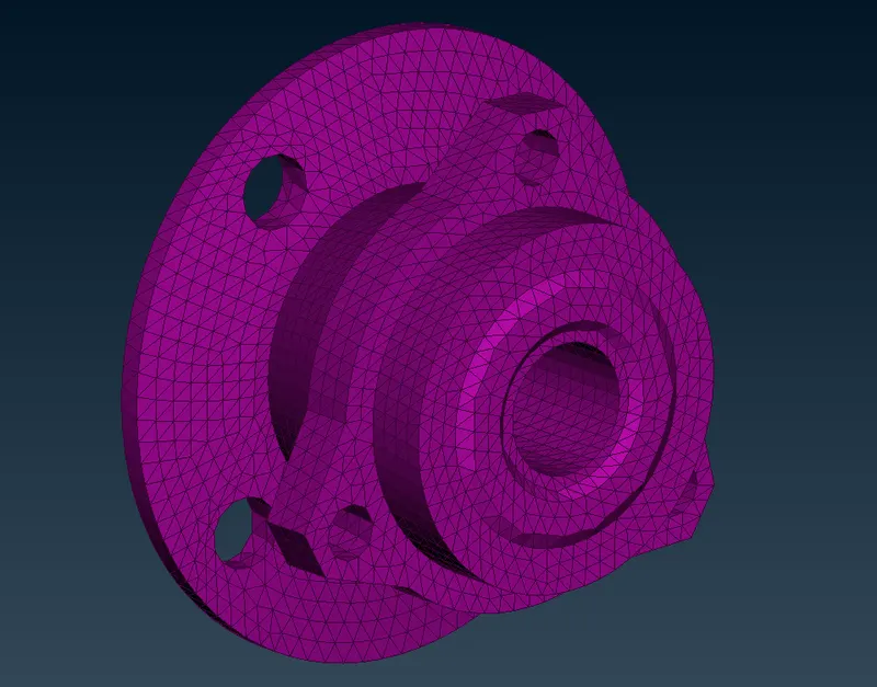
Tyre and Rim Brake Hub
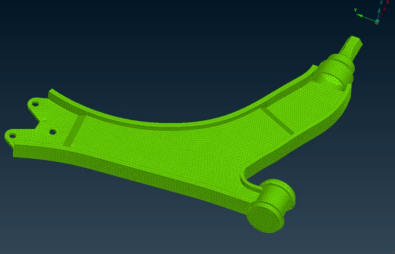
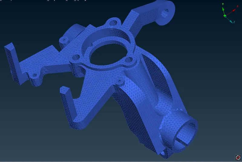
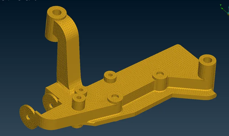
Control Arm Knuckle Joint Frame
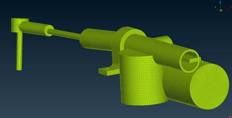
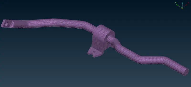
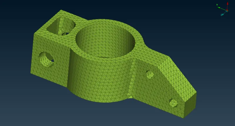
Assembly Rod Say Bar Rod Bush
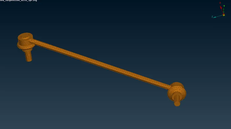
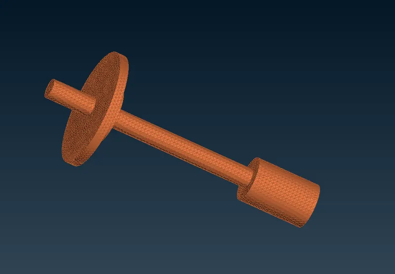
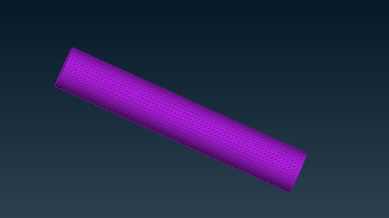
Link Bar Connecting Rod Rod
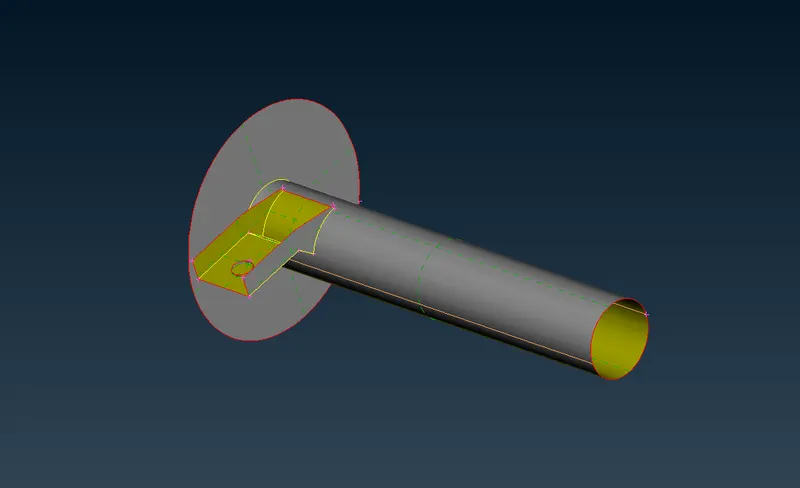
Mid-surface extraction for the shell meshing components:
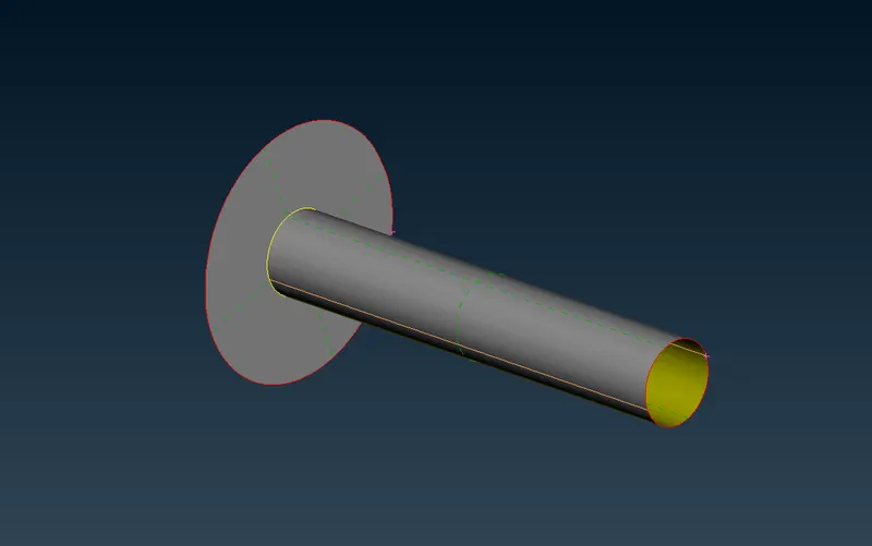
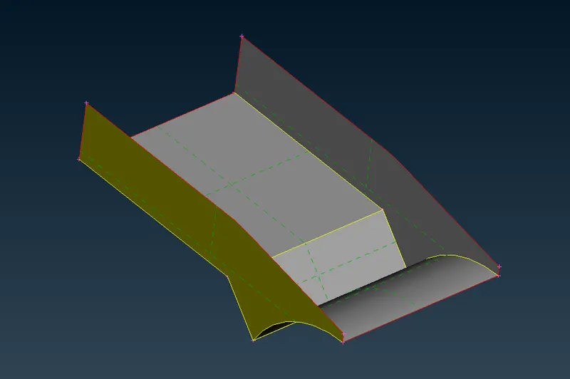
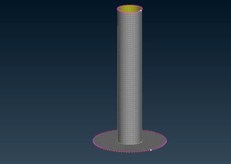
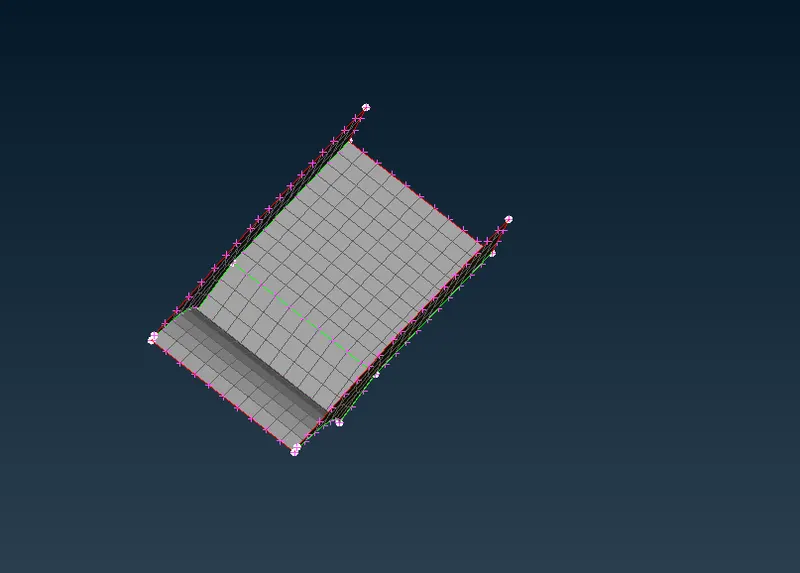
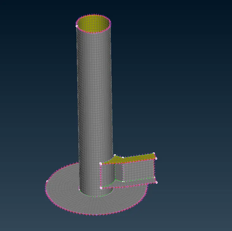
2-D Mesh Performed on the Extracted Mid-surface:
Suspension Assembly after Volume Mesh:
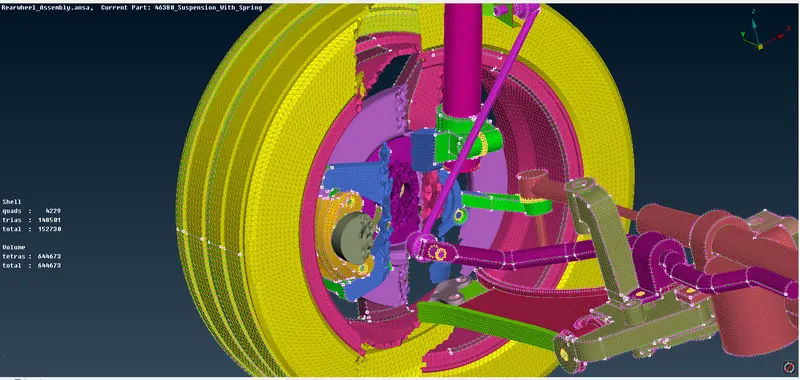
The above pictures represent the volume mesh performed on the Rear suspension assembly component with different PIDs following the respective parameters given for this component.
Assigning Connections to the Component:
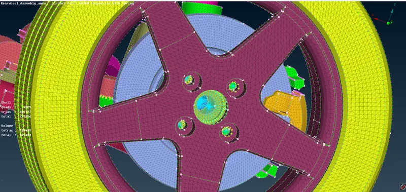
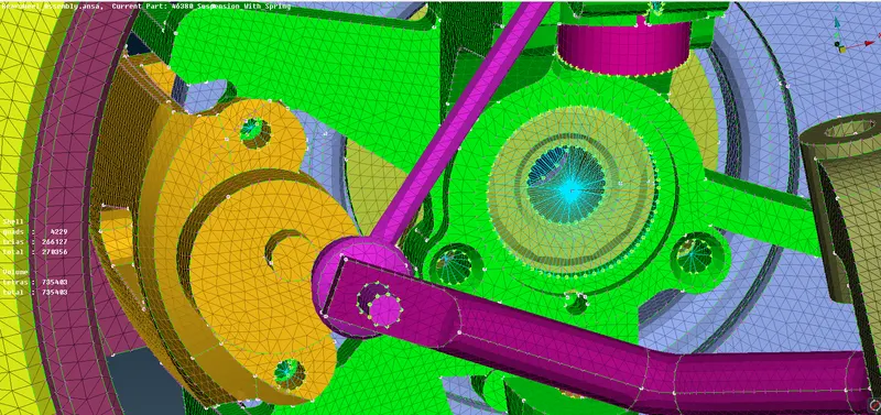
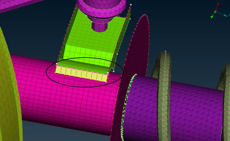
The above pictures represent the rigid connections assigned to the components. In order to connect from one component to the other components respectively.
Assigning Thickness:
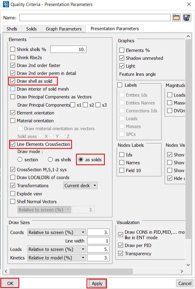
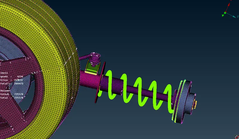
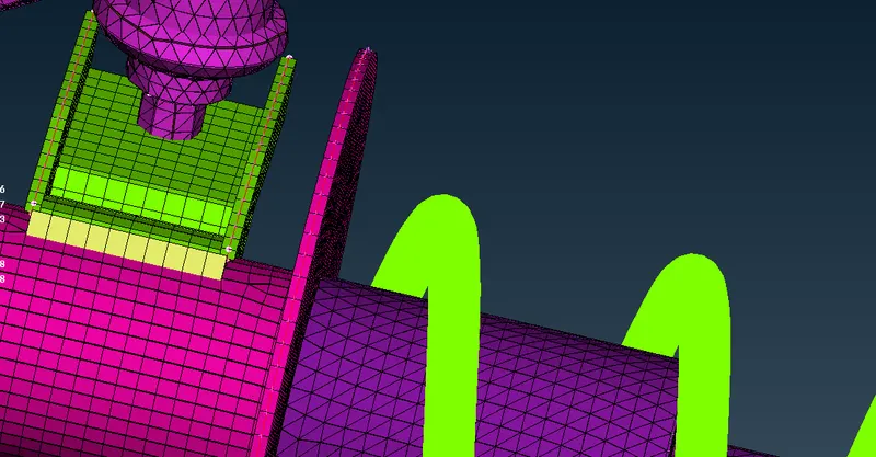
The above pictures represent the thickness assigned to the components to which mid-surface has been extracted for the thickness below 5 mm and assigned thickness to it accordingly.
Final Component after working on:
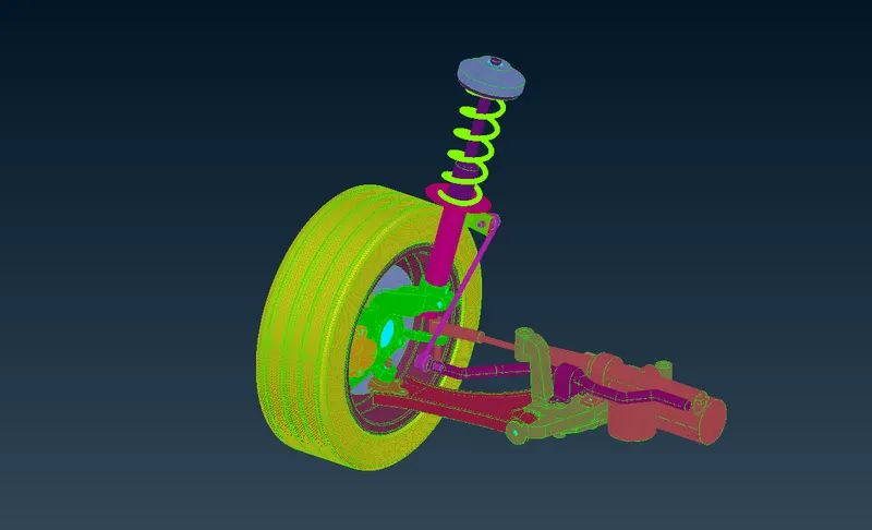
The above picture represents the suspension assembly component after working on the CAD component with all the required parameters assigned to be. Now, we do symmetry to this component in order to watch it as a full component.
Full Model after Symmetry:
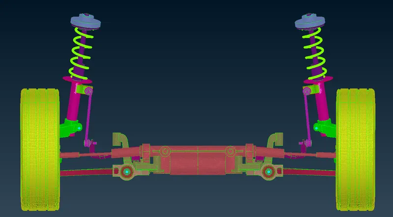
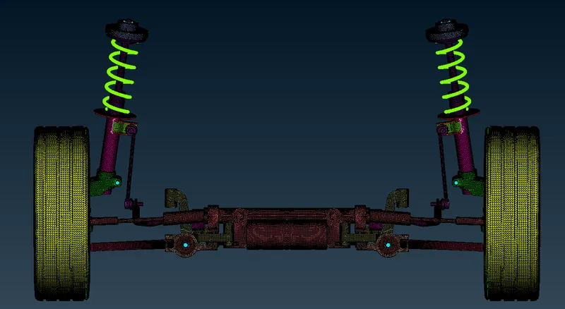
The above picture represents the full model of the rearview suspension assembly of the passenger car vehicle with thickness assigned to it.
Learning Outcomes:
- Manual Geometry Cleanup
- The meshing of 1D, 2D shell, and 3D solid Elements.
- Deploying of Connections to the Suspension Model Components.
- Setting different PIDs to components in the model.
- Thickness Assignment.
- Knowledge of the Suspension System and its components.
Conclusion:
The suspension assembly has meshed with Tetra and Shell Meshing on the suspension assembly of a passenger car vehicle in the ANSA Interface. The Components that were having below 5 mm thickness were captured with 2-d meshing and components having more than 5 mm thickness were followed with the volume mesh by following quality criteria and meshed the components with the respective parameters and deployed with the appropriate connections to the suspension assembly model by assigning thickness to it at the end.