Mechanical design of battery pack
Objective: To design a battery pack with a capacity of 18 kWh with Cell: ANR26650M1-B
Theory:
Without batteries, there would be no cell phones, watches, tablets, hearing aids, flashlights, electric cars or communication satellites – and the list goes on. The first battery was invented over 200 years ago, and ever since then, these ingenious devices have become indispensable in our daily lives.
What is a Battery ?
A battery is any device that can provide a portable temporary source of electrical energy.
In an electric circuit, batteries serve as a power source by creating a potential difference that drives the flow of electric current. As current passes through the circuit, it transfers energy to any devices connected to it. In such a circuit, the type of current that flows is direct current. In other words, the current that flows goes in one, continuous direction.
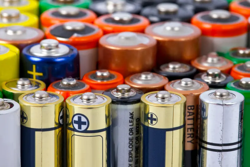
The composition of a battery differs depending on the type--alkaline, lithium or zinc chloride. Batteries come in all shapes and sizes and are available in a wide range of strengths, in terms of power. The one thing in common with any type of battery is the way it works. Batteries move energy from one end of the cell to the other, creating a current that can be used to supply power to many devices.
Working of a battery:
A battery, or cell, is composed of a cathode, an anode and the electrolyte. A chemical reaction takes place within the cell, moving electrons from one place to another and producing an electric current. Half of the cell contains electrolyte and an anode. The other half contains electrolyte and a cathode. Electrons gather at the negative end of a battery (the anode). When a wire is connected from the positive end (the cathode) to the negative end, the electrons move through the cell from the anode to the cathode.
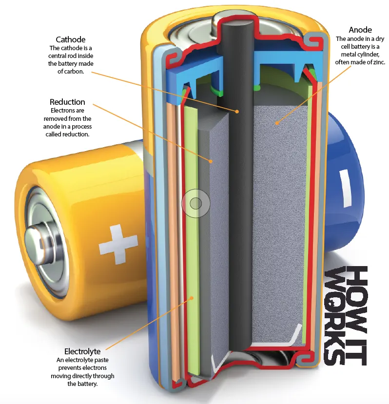
The anode is the part of the battery that gives up electrons. While discharging energy, the anode is the negative electrode. When charging a cell, the anode becomes the positive electrode. In alkaline batteries, the anode is usually made up of zinc powder. To limit corrosion, zinc oxide is usually added to the anode.
The cathode is the part of the battery that absorbs electrons. While discharging energy, the cathode is the positive electrode. When charging a cell, the cathode becomes the negative electrode. In alkaline batteries, the cathode is usually made up of manganese dioxide. To improve conductivity, graphite is traditionally used in the cathode.
Electrolyte is the conductive substance that transmits energy through the cell. The anode and cathode never touch; they are connected to each other via electrolyte. Electrolytes can come either in solid or liquid form. Materials usually used for electrolytes are potassium hydroxide, ammonium chloride or zinc chloride.
Separators are porous materials that prevent the anode and cathode from touching, which would cause a short circuit in the battery. Separators can be made from a variety of materials, including cotton, nylon, polyester, cardboard, and synthetic polymer films. Separators do not chemically react with either the anode, cathode, or electrolyte.
Operation of Batteries generally require several chemical reactions in order to operate. At least one reaction occurs in or around the anode and one or more reactions occur in or around the cathode. In all cases, the reaction at the anode produces extra electrons in a process called oxidation, and the reaction at the cathode uses the extra electrons during a process known as reduction.
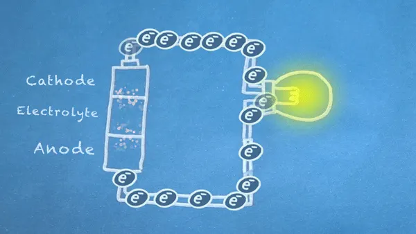
A reduction-oxidation reaction into two separate parts. Redox reactions occur when electrons are transferred between chemicals. We can harness the movement of electrons in this reaction to flow outside the battery to power our circuit.
Anode Oxidation:
This first part of the redox reaction, oxidation, occurs between the anode and electrolyte, and it produces electrons (marked as e-).
Cathode Reduction:
The other half of the redox reaction, reduction, occurs in or near the cathode. Electrons produced by the oxidation reaction are consumed during reduction.
Procedure:
Given cell is ANR26650M1-B
To design a battery pack with the given ANR26650M1-B cell we have to go through the data sheet and collect the relevant data.
ANR26650M1-B Cell Specifications
Nominal Ratings
Voltage: 3.3 Volts
Capacity: 2.5 Ah
Energy: 8.25 Wh
Specific Power: 2600 W/kg
Impedance (1KHz AC Typical) 6 mΩ
Cycle Life at 1C/1C, 100% DOD: > 4000 cycles
Cell Type: 26650 Lithium Ion Power Cylindrical Cell
Discharging
Max Continuous Discharage: 50 A
Max Pulse Discharge Current >50% SOC (10s): 120 A
Minimum Voltage: 2 Volts
Temperature: -30ºC to 55ºC
Charging
Recommended Standard Charge: 2.5 Amps
Max Charge Rate: 10 Amps
Max Pulse Charge Current <50% SOC (10s): 25 A
Float Voltage: 3.45 Volts
Recommended charge V & Cut-off Current: 3.6 Volts, taper to 125mA
Temperature (reduce charging current to 250mA when under 0ºC): 0ºC to 55ºC
Mechanical
Diameter: Ø25.96 +/- 0.5 mm (1.0")
Length: 65.15 +/- 0.5 mm (2.6")
Mass: 76 g
In order to create a battery pack with the capacity of 18 kWh we do the calculations according to the requirement of the battery pack.
Nominal Voltage = 3.3V
Nominal Capacity = 2.5Ah
Energy capacity = nominal voltage * nominal capacity
= 3.3*2.5
= 8.25kWh
Assumptions taken to create a battery pack:
No of series cells = 4
No of parallel cells = 9
Volume of module for series = Nominal voltage * No of series cell
= 3.3*4
= 13.2
For capacity in parallel = No of parallel cell * cell capacity
= 9*2.5
= 22.5
No of series module = Total volume of pattery pack/volume of the module in series
= 50/13.2
= 3.7878
Pack energy capacity = 18000wh/50V
= 360
No of parallel modules = 360/22.5
= 16
Here from the above calculations
Total Capacity = (No of series module) * (No of parallel module) * (No of series * 3.3V) * (No of parallel * 2.Ah)
= 4 * 16 * (4*3.3) * (9*2.5)
= 19008 kWh
The above calculations are done in the excel sheet as well link is given below for the reference.
https://docs.google.com/spreadsheets/d/1oMKFx2Mp8ztMqkAG4pP5ssarsYr6qLrU5hUEK_5eSRc/edit#gid=0
Mechanical Design of a Battery Pack in CATIA:
The cell which is given to us was carried as reference and designed the same in the CATIA V5 by foolowing the mechanical criteria given in the cell data sheet.
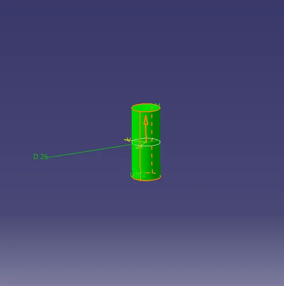
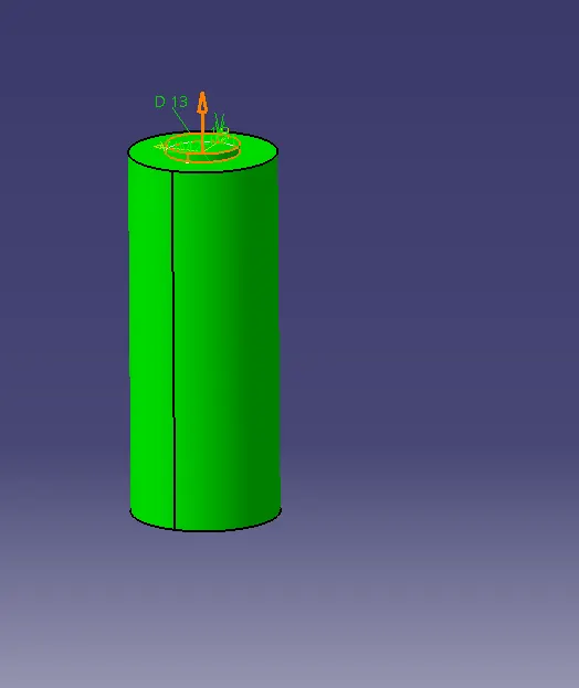
The above figure represents the dimensions taken for the positive terminal and the diameter of the cell.
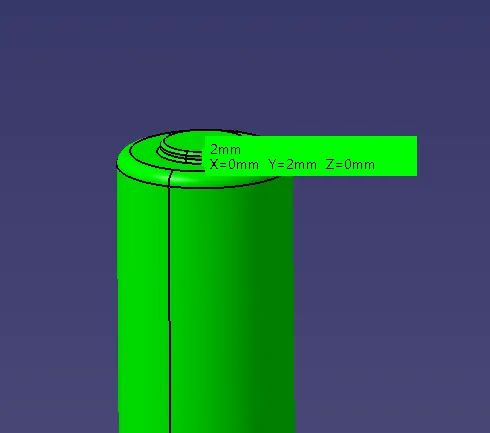
The above figure represents the fillet assigned to the cell with the thickness of 2mm.
Now the cells are formed for 4S and 9P in the form of module pack. which is seen in the below figure.
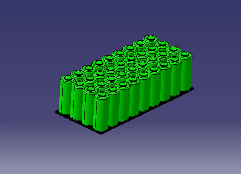
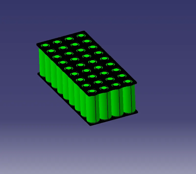
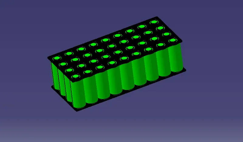
The above figure represents the mounting of the battery module in the form of connections.
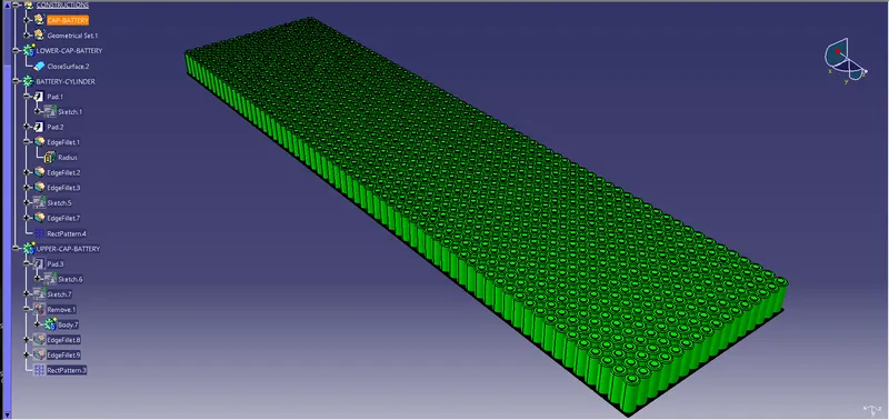
The above figure represents the full battery pack of the module.
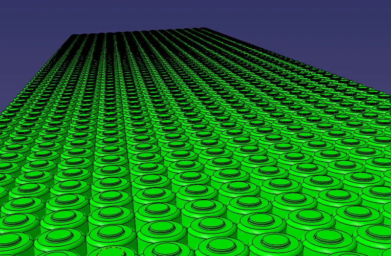
The above figure represents the perspective view of the battery pack modules.
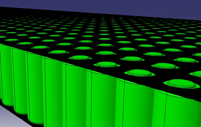
The above figure represents the side view of the battery pack module.
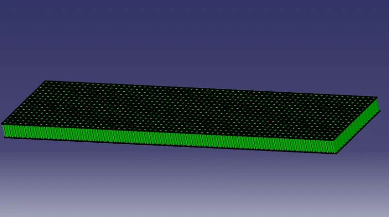
The above figure represents the final battery pack module with the achieved battery pack capacity which is modelled by following all the criteria from the cell data sheet which is used as an reference and designed accordingly.
Conclusion: Therfore the battery pack has been designed for the given cell by achieving the battery pack capacity.