2D meshing on the instrumental Panel
AIM: To perform the 2-D Mesh on the given Instrumental Panel of an Automotive component using ANSA Interface.
Objective:
- To examine the geometrical errors and fix them.
- To extract mid surface manually and Mesh according to given quality Criteria.
- To Assign Thickness according to its PID.
- To follow the below quality criteria.
|
S.No |
Quality Criteria |
Value |
|
1 |
Target/Average length |
4 |
|
2 |
Minimum Length |
2 |
|
3 |
Maximum Length |
6 |
|
4 |
Aspect |
3 |
|
5 |
Warpage |
15 |
|
6 |
Skewness |
45 |
|
7 |
Jacobian |
0.7 |
|
8 |
Minimum Quad Angle |
45 |
|
9 |
Maximum Quad Angle |
135 |
|
10 |
Minimum Tria Angle |
30 |
|
11 |
Maximum Tria Angle |
120 |
|
10 |
Tria Percentage |
15 |
Theory:
What does Meshing Mean?
Meshing is an integral part of the engineering simulation process where complex geometries are divided into simple elements that can be used as discrete local approximations of the larger domain. The mesh influences the accuracy, convergence, and speed of the simulation. Furthermore, since meshing typically consumes a significant portion of the time it takes to get simulation results, the better and more automated the meshing tools, the faster and more accurate the solution.
Why do we perform Mesh?
The basic idea of FEA is to make calculations at only a limited number of points and then interpolate the results for the entire domain (surface or volume). Any continuous object has an infinite degree of freedom and it's just not possible to solve the problem in this format. The finite element method reduces the degree of freedom from infinite to finite with the help of discretization or meshing (nodes and elements).
Importance of Proper Meshing in Finite Element Analysis:
Predictive computational models of real-world scenarios are commonly used during the product development process. Engineers and scientists use finite element analysis, also known as FEA to build these models. The use typically begins with a computer-aided design (CAD) model that represents the physical parts being simulated as well as knowledge of the material. This information enables the prediction of real-world behavior, often with very high levels of accuracy. Proper meshing plays a critical role during this process.
2-D Meshing:
The 2D Mesh module is used to construct two-dimensional finite element meshes. The mesh consists of nodes that are grouped together to form elements. Numerous tools are provided for automated mesh generation and mesh editing. 2D meshes are used for modeling and to aid in the construction of 3D meshes.
Instrumental Dashboard Panel in Automotive Vehicle:
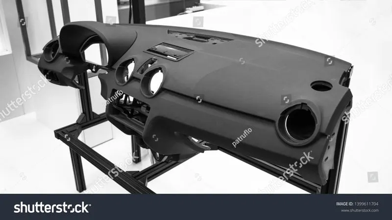
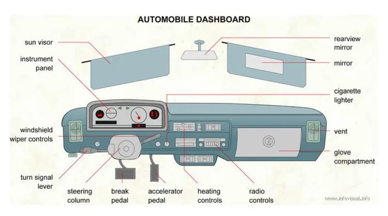
A dashboard (also called dash, instrument panel (IP), or fascia) is a control panel set within the central console of a vehicle or small aircraft. Usually located directly ahead of the driver (or pilot), it displays instrumentation and controls for the vehicle's operation.
Instrument panel (IP), as the largest inner trim parts which directly shown to passengers, have not only beauty and function requirements but also NVH and safety request. The vibration and noise on the dashboard can be directly felt by passengers. Thus the modal analysis of the instrument panel plays an important role in the NVH character of the whole vehicle.
CAE analysis is a very efficient way to study the NVH character. As it can help shorten the test cycle and reduce development costs, CAE analysis is widely used during automotive development procedures.
Procedure:
The procedure for performing 2-D meshing on the given Instrumental Panel component is as follows below.
Importing the Geometry file in the ANSA interface:
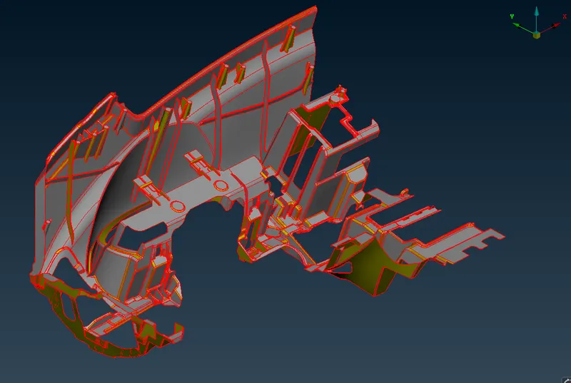
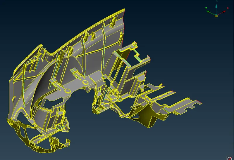
The above two pictures represent the CAD model of the Instrumental dashboard panel. The 1st picture is without the Topology Clean up and the 2nd picture is after performing the Topology clean up. In order to clean up the geometry, Topology clean-up is a must process to perform before proceeding to extract mid-surface and meshing it.
Examining the Geometrical errors in the Component:
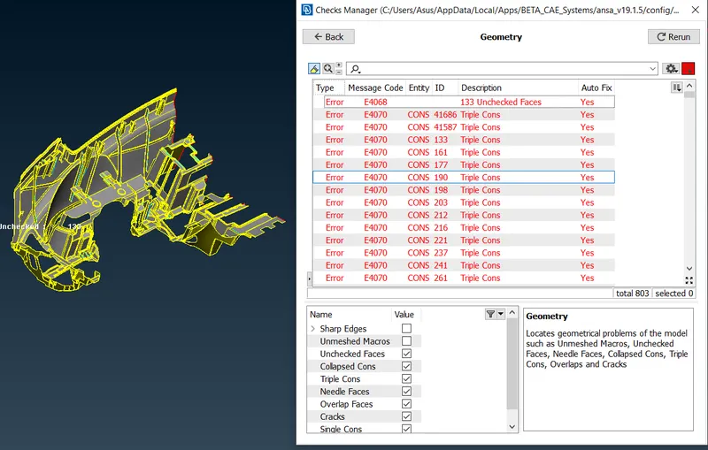
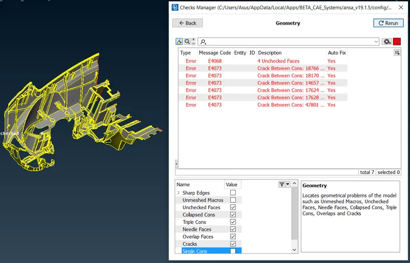
The above picture represents the geometrical errors that are been detected in the Instrumental component. In order to extract mid-surface this component further, we should clean up these geometrical errors. There are some errors that can be fixed in a single shot with auto fix and there are some errors like unchecked faces, cracks between cons, and needle face errors that are to be fixed manually by examining them individually.
Cleaning up the Geometry:
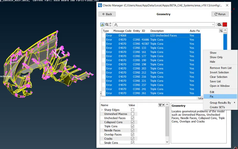
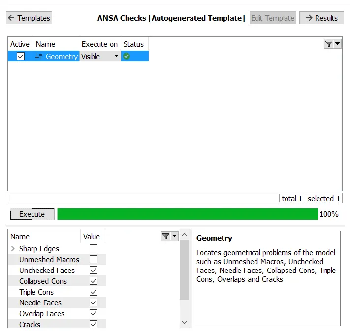
The above two pictures represent the clean-up geometry of the component which is been fixed automatically and fixed manually in some places. The 2nd picture indicates that we are set to extract mid-surface and then proceeded for the meshing on the component.
Mid-surface Extraction:
In order to Extract mid-surface, we should be familiar enough with the thickness of the particular region to set a PID with the respective name and thickness of the region. So here in this case we measure the thickness of the component where the mid-surface is to be extracted and set a PID accordingly.
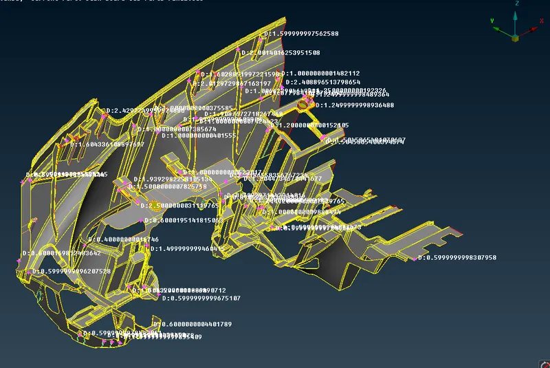
The above picture represents the Thickness measurement of the component in order to assign thickness after meshing the component.
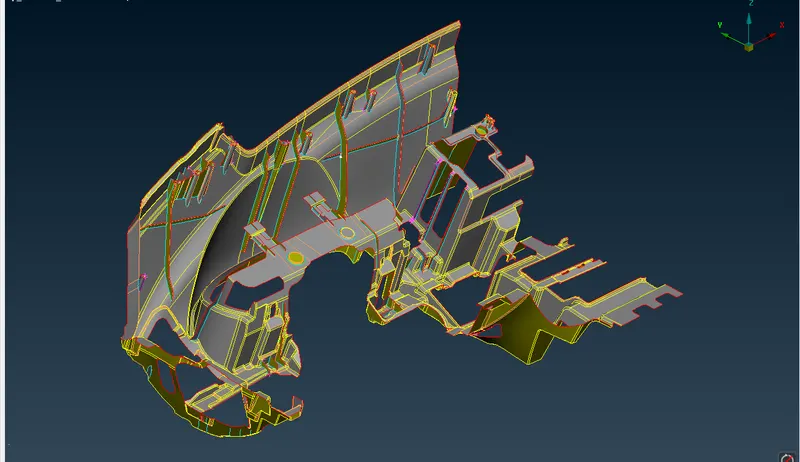
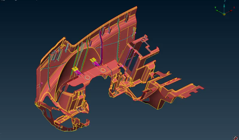
The above two pictures represent the mid-surface extraction of the instrumental dashboard component of an automotive vehicle with entity and PID modes respectively. The 1st picture represents the mid-surface extraction in the entity mode whereas, The 2nd picture represents the mid-surface extraction in the PID mode.
Some of the pictures with created PID regions.
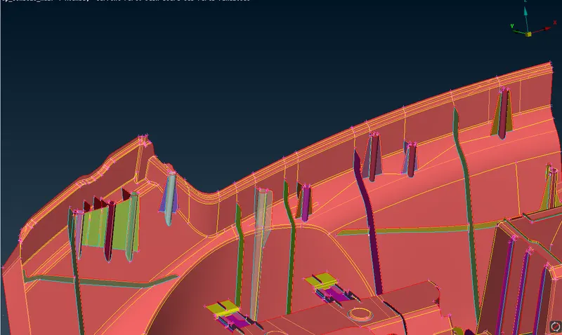
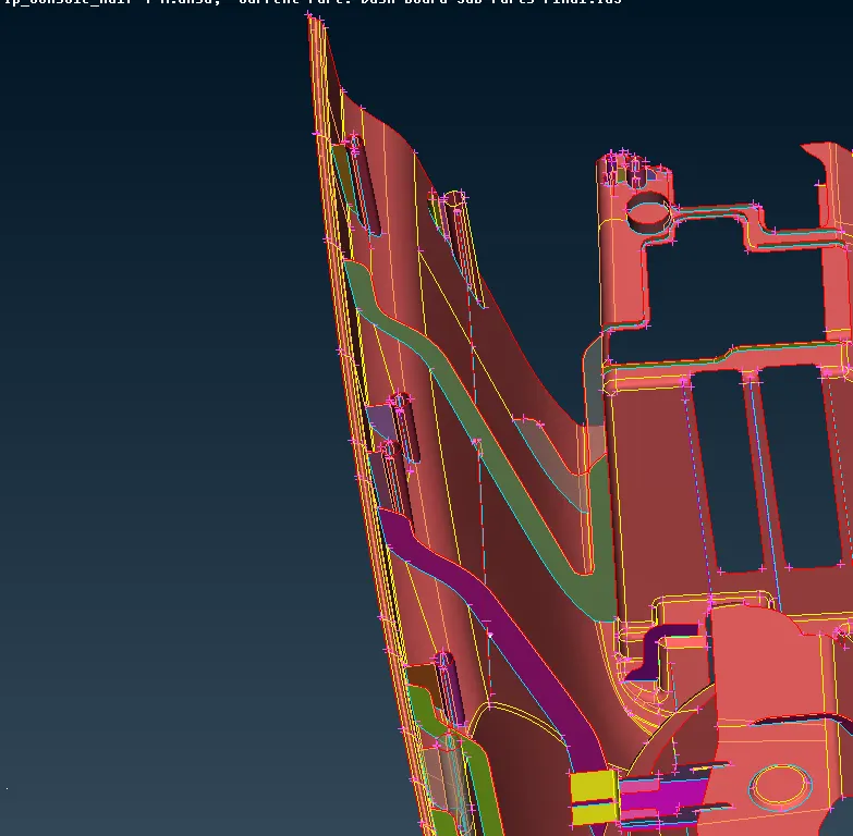
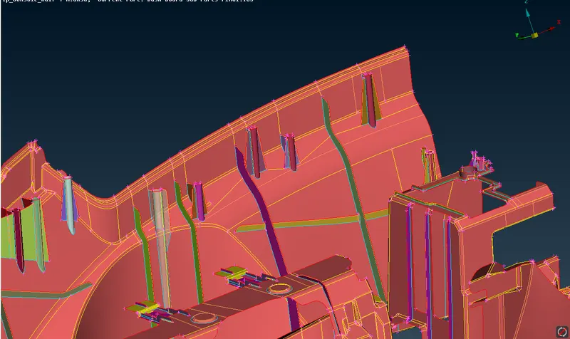
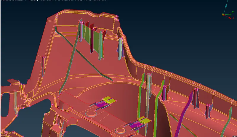
The above picture represents the PID regions of the component that have been created according to its thickness and geometrical parameters.
Meshing of the Component:
Mehing is performed on the component by following the quality criteria that is been given to us.
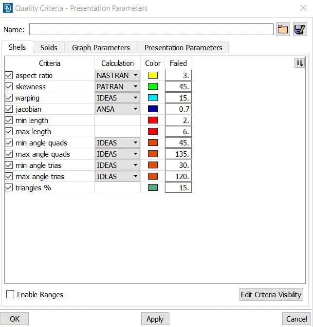
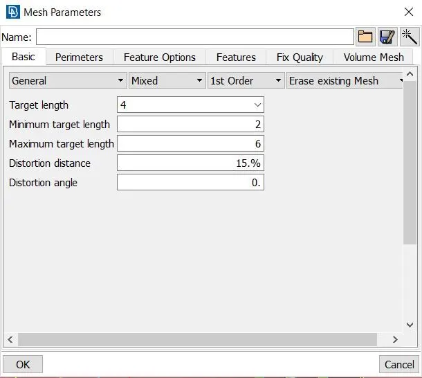
The above two pictures represent the quality criteria and mesh parameters detail that are been followed to this model in order to perform mesh on this component.
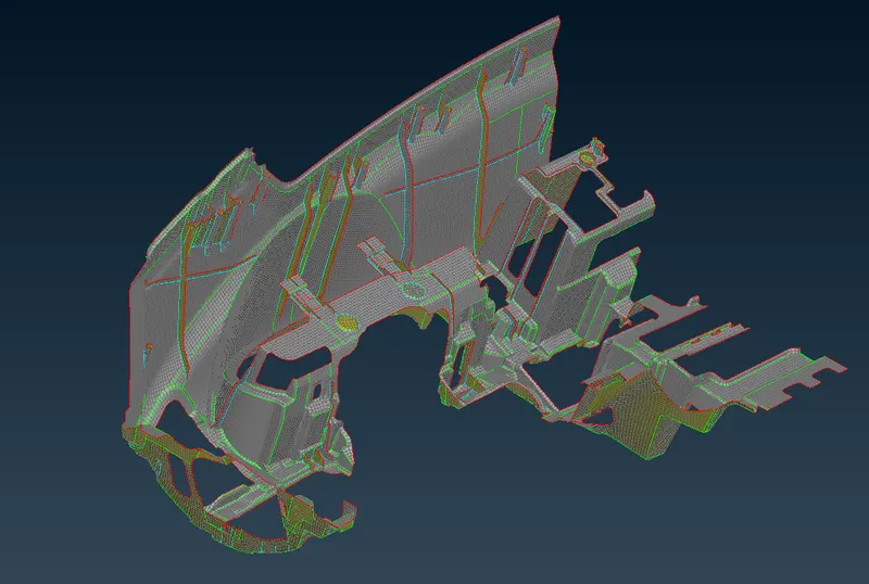
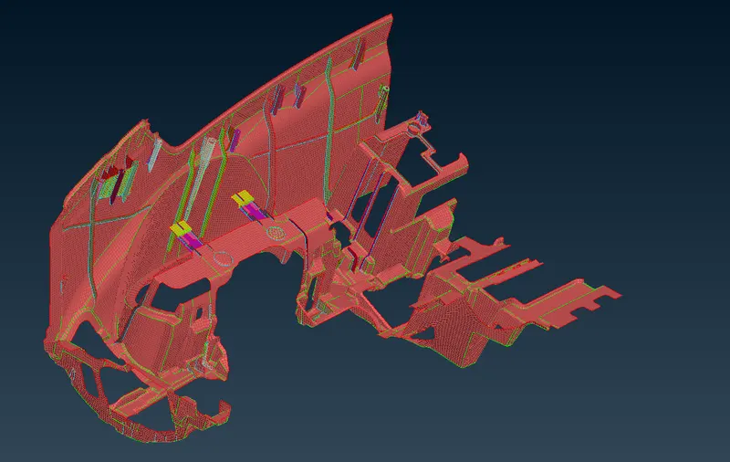
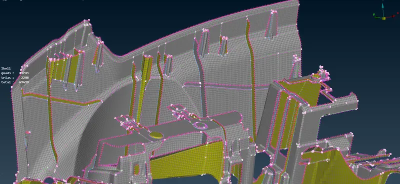
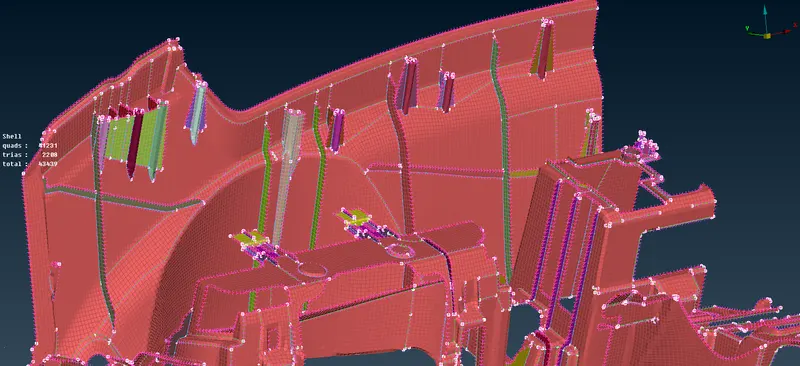
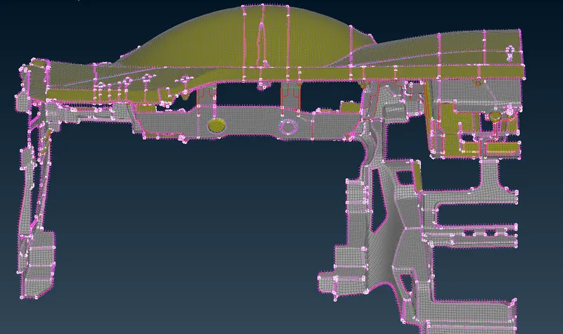
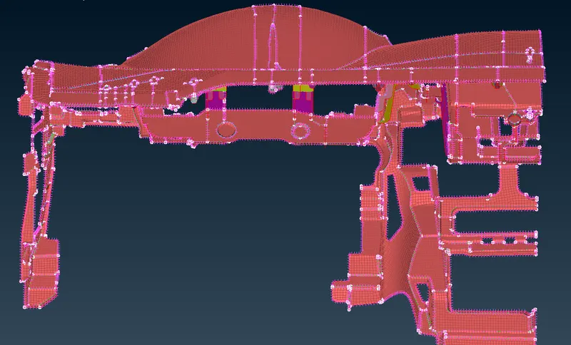
All the above pictures represent the 2-D meshing on the instrumental dashboard panel following the quality criteria and mesh parameters which is been shown above.
Assigning Thickness:
The Thickness is been assigned to the component according to the PID created in the ANSA Interface.
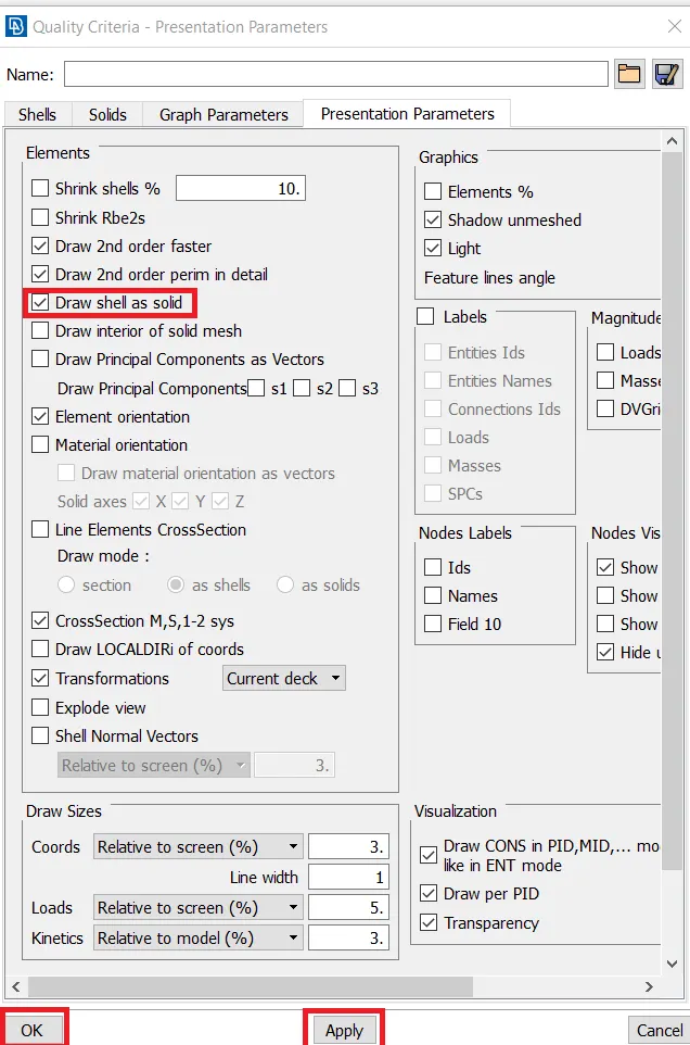
From the above picture by checking the drawn shell as solid and applying it gives us the thickness of the component.
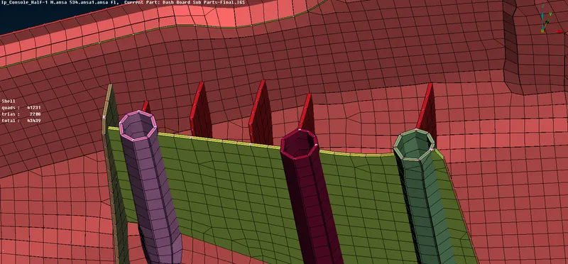
The above picture confirms that the thickness is been successfully applied to the component by following the PID.
Learning Outcomes:
- Manual Geometry Clean-up
- Mid-surface extraction in critical areas
- Tools like faces middle and curve middle been an exposure to extract mid-surface.
- Extending and joining the conical and circular surfaces to the base surface.
- Clearing the Off elements.
Conclusion: Therefore, The 2-D Meshing on the given Instrumental Panel of an Automotive component has been performed using ANSA Interface following the given quality criteria.