Meshing of Door Inner Panel using Hyper Mesh
Objective: To Perform the mesh on a Side door inner panel with following the quality criteria and assigning thickness.
Test case:
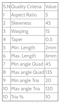
The above picture represents the quality criteria that we have to assign in the criteria file settings.
Theory:
What does Meshing Mean ?
Meshing is an integral part of the engineering simulation process where complex geometries are divided into simple elements that can be used as discrete local approximations of the larger domain. The mesh influences the accuracy, convergence and speed of the simulation. Furthermore, since meshing typically consumes a significant portion of the time it takes to get simulation results, the better and more automated the meshing tools, the faster and more accurate the solution.
Why do we perform Mesh ?
The basic idea of FEA is to make calculations at only limited number of points and then interpolate the results for the entire domain (surface or volume). Any continious object has infinite degree of freedom and it's just not possible to solve the problem in this format. Finite element method reduces the degree of freedom from infinite to finite with the help of discretization or meshing (nodes and elements).
Importance of Proper Meshing in Finite Element Analysis:
Predictive computational models of real-world scenarios are commonly used during the product development process. Engineers and scientists use finite element analysis, also known as FEA to build these models. The use typically begins with a computer-aided design (CAD) model that represents the physical parts being simulated as well as knowledge of the material. This information enables the prediction of real-world behavior, often with very high levels of accuracy. Proper meshing plays a critical role during this process.
Procedure:
Import of the given model
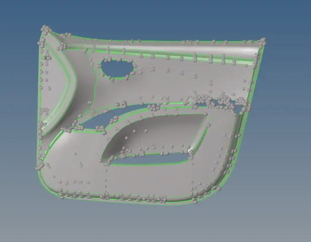
The above model which is in the picture represents the side door inner panel of a passenger vehicle. Here in this case we have to extract the mid surface manually and perform the mesh with following the quality criteria and assign thickness to it.
Extracting the Manual Mid surface:
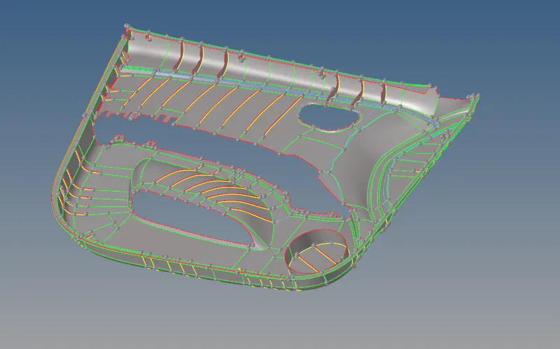
Here the above picture represents the manual mid surface extraction of the side door inner panel of the passenger vehicle. where in some regions we work on the offset method to extract the mid-surface and surface to surface in some other regions.
Quality Criteria:
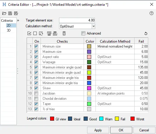
The above picture represents the quality criteria that are to be followed by the given criteria to ensure that the elements should not failed in the mesh that we perform.
Meshing of the Model:
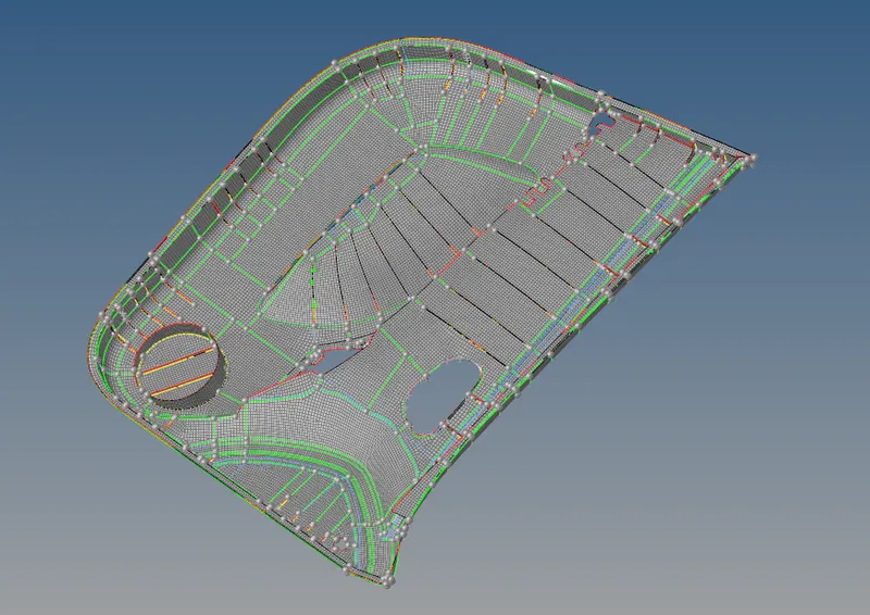
Here from the above picture it represents the meshing on the side door inner panel of the passenger vehicle deliberately. There were some some errors that took place in this process of meshing but we overcome it by approaching in a different manner to fix it out.
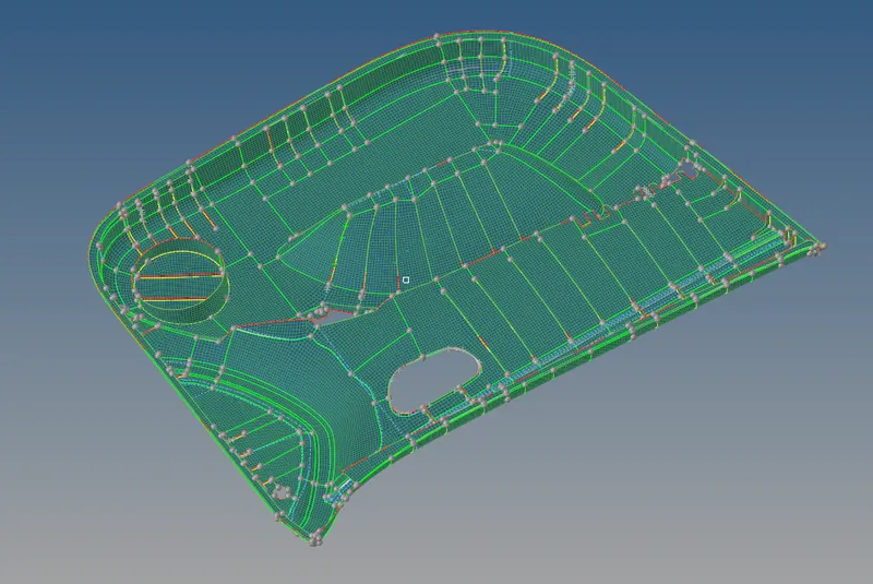
The above picture represents the quality index of the particular model where it highlights the failing elements with the color indication and morever what type of quality is getting failed. as we look into this above model we can ensure that no element is getting failed and reaching the quality parameters without any fail.
Assigning Thickness:
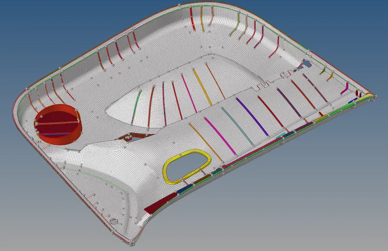
Here the above pictrure represents the assigned thickness to the mesh that we have generated followed by creating a property card where we allocate the certain thickness to the component according to it's relevant thickness.
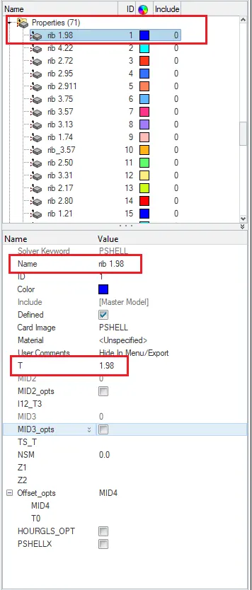
similarly these property cards are prepared for the every individual parts or regions in this component according to it's thickness.
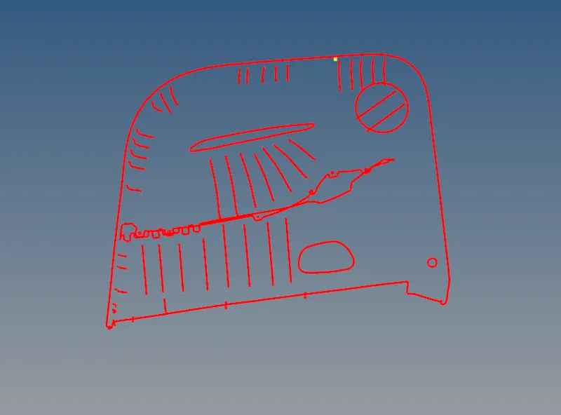
Here the above picture represents the edges and no free edges are present in between the component.
Conclusion: Therfore a proper mesh flow has been performed on the side door inner panel of an passenger vehicle by meeting all the quality parameters without any fail and assigning the thickness to it.