Neon Side Pole Crash Test Analysis on a BIW(Body in White) by Using Crashworthiness and RADIOSS
Objective: To perform Neon Side crash analysis of the BIW Model and study the impact of the crash using Hyper crash & Radioss.
1) Introduction :
A crash simulation is a virtual recreation of a destructive crash test of a vehicle using a computer simulation to examine the level of safety of the vehicle and its occupants. Data obtained from a crash simulation indicate the capability of the vehicle body to protect the vehicle occupants during a collision against injury. This simulation technology has greatly increased the protection, dependability, and producing potency in today’s vehicles. The advantage of the simulation is numerous and important. Computer-aided parametric design software will be used for modeling of the problem to define all the coordinate values and geometrical details, then this CAD data would be transferred to FEM software for pre-processing, solution, and post-processing followed by generation and
interpretation of results related to energies, acceleration, and displacements with different loads & boundary conditions possible in various accidental situations. The automotive industry has probably the widest application of crash simulation. Simulating the crashworthiness of the vehicle in terms of very simple models based on the spring-mass damper systems was the focus when the computers were very slow and the breakthrough occurred when LSTC was formed. Nowadays software such as LS DYNA and others have very wide practical aspects by incorporating special seat belt elements and passenger dummies for simulating precisely the occupant safety under various crash situations. Several standards have been originated in various countries related to automobile crashing. Although developed mainly for automotive applications, crash simulation software’s have also found application in train, ship and aircraft crashworthiness. The two main standards associated with FAA (Federal Aviation Administration) requirements are those of bird strike impact and engine blade containment. Other applications in the defense sector are simulating the explosive detonation process and design of weapons. Computational Biomechanics also is continuously evolving with the development of finite element models closely following the actual physics models.
Finite Element Analysis :
Simulation using finite element method comprises of three major phases:
(i) pre-processing
In which the analyst develops a finite element mesh to divide the subject geometry into sub-domains for mathematical analysis, and applies material properties and boundary conditions.
(ii) solution
During which the program derives the governing matrix equations from the model and solves for the primary quantities.
(iii) post-processing
In which the analyst checks the validity of the solution, examines the values of primary quantities (such as displacements and stresses), derives and examines additional quantities (such as specialized stresses and error indicators).
Crash Test :
A crash test is a form of destructive testing usually performed to ensure safe design standards in crashworthiness and crash compatibility for various types of vehicle like small, medium, and heavy-duty and its related systems and components for the sake of getting the performance of the vehicle under the different conditions of the crash at different angles with taking certain object like a rigid wall, cables specially three-strand cable, concrete barriers, guardrail systems, etc. It will be performed either by numerical simulations or experimentally. depicts different types of crash tests generally used.
Side Impact Test:
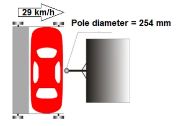
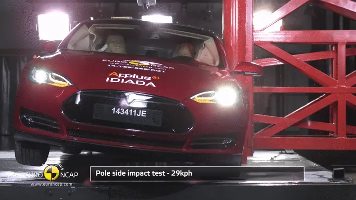
In this test, the vehicle is positioned sideways on a moving platform and sent into a stationary rigid pole at a speed of 29 km/h.
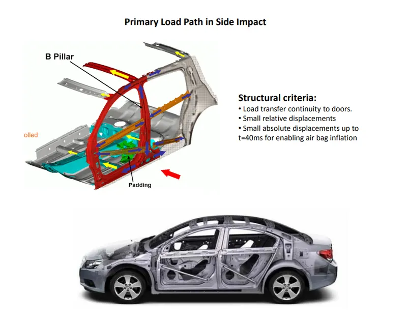
For a better view let us a look at the interior part when it is undergoing a side crash.
2) Procedure:
Unit Systems:
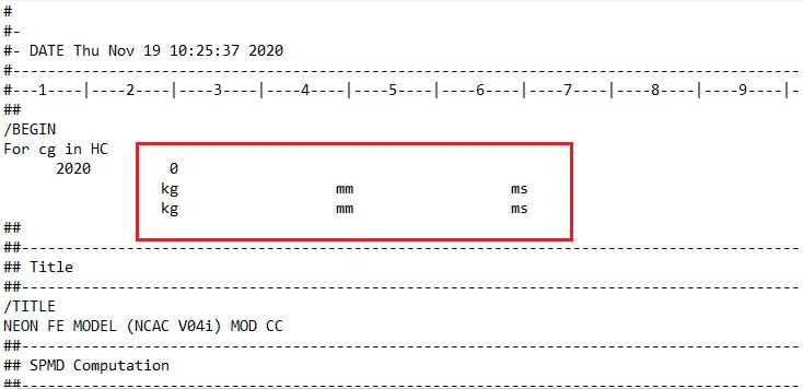
We check the units from the read file to be familiar with the parameters that we apply in different conditions.
Creation of a New Interface:
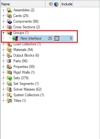
Here from the above figure, we can see that a new interface is been created with the name New Interface 25. After the creation of the new interface, we give all the recommended parameters for this interface which as below.
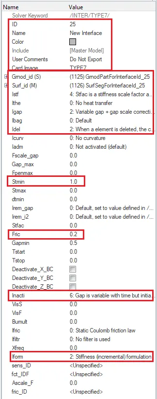
The above-highlighted icons are the recommended parameters that are required to be. After the creation of the new interface, we review the interface after selecting the slave and master in the interface card.
Review of the Interface card:
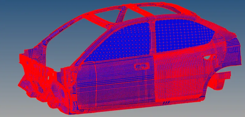
Here from the above figure, it denotes that red-colored nodes are called the slave nodes and the blue colored nodes are called the master nodes.
Penetrations Check:
In this case, we make sure that no penetrations should take place and better avoid the penetrations if there are any.
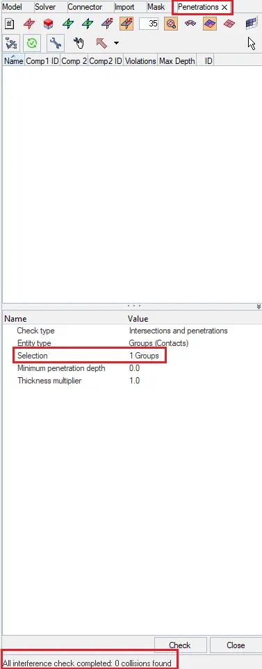
Here from the above card, we see the result of the penetrations check which is highlighted below saying that all the interference checking was completed with zero collisions.
Creation of a Rigid Wall:
In this case, we create a rigid wall as we are impacting the vehicle on the pole. There are certain constant parameters like diameter which should be constant.
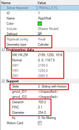
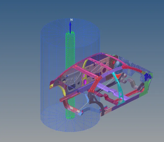
Here we can see that the proper rigid wall is created with all the given parameters which are all required to be there for the creation of the rigid pole.
Center of Gravity:
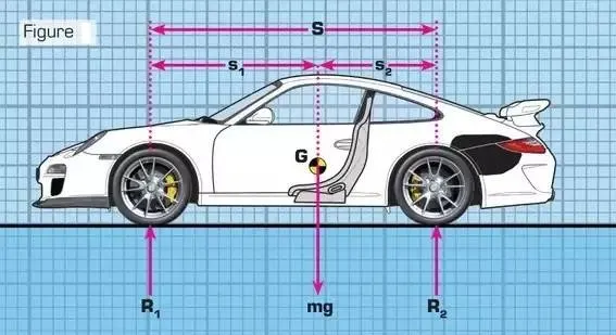
The Center of gravity, also known as the center of mass, is that point at which a system or body behaves as if all its mass were centered at that point. Where the weight, and also all accelerative forces of acceleration, braking, and cornering act through it.
- Center of gravity location can be defined as:
- The balance point of an object
- The point through which a force will cause pure translation
- The point about which gravity moments are balanced
- The point which if the body is hanged from it will stay balanced (leveled as it is on the ground).
What is the importance of CG?
When analyzing the forces applied to the car, the CG is the point to place the car's weight, and the centrifugal forces when the car is turning or when accelerating or decelerating. Any force that acts through the CG does not tend to make the car rotate.
The center of mass height, relative to the track, determines load transfer, (related to, but not exactly weight transfer), from side to side and causes body lean. When tires of a vehicle provide a centripetal force to pull it around a turn, the momentum of the vehicle actuates load transfer in a direction going from the vehicle's current position to a point on a path tangent to the vehicle's path. This load transfer presents itself in the form of body lean. Body lean can be controlled by lowering the center of weight or widening the car track, it can also be controlled by the springs, anti-roll bars, or the roll center heights.
The center of mass height, relative to the wheelbase, determines load transfer between front and rear. The car's momentum acts at its center of mass to tilt the car forward or backward, respectively during braking and acceleration. Since it is only the downward force that changes and not the location of the center of mass, the effect on over/understeer is opposite to that of an actual change in the center of mass.
A lower center of mass is a principal performance advantage of sports cars, compared to sedans and (especially) SUVs. Some cars have body panels made of lightweight materials partly for this reason.
Setting Up Center fo Gravity and Balancing the mass equivalent to the Full car Model:
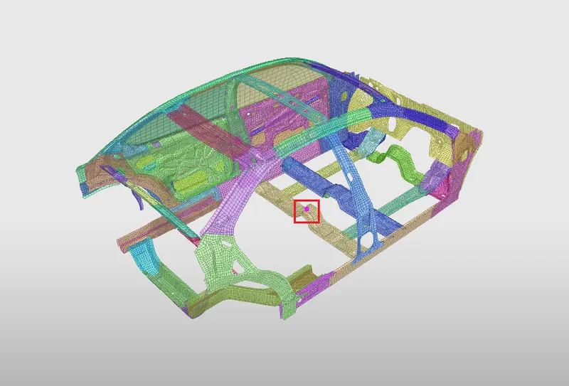
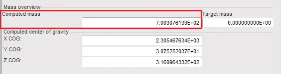
Here in the above figure, the CG is placed on the cross member where the sectional forces are been applied and the excess mass has been added in the different portions to reach the target mass which is 700kg matching with the full car model criteria.
Initial velocity:
For the side pole crash, the initial velocity will be 8.94 mm/ms which is a constant and recommended velocity for the side pole crash analysis which we have been discussed earlier.
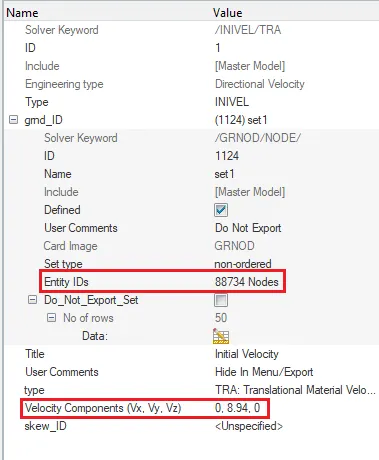
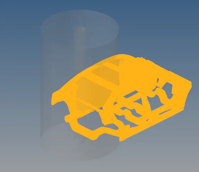
Here we give the initial velocity in the y-direction as our rigid pole is in the y-direction.
Review of Initial Velocity:
Assigning Time Step and run time:
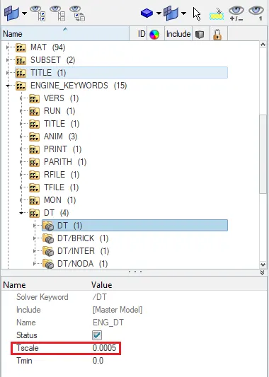
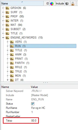
Here we give the time steps as 0.0005 ms as it was in 0.5 microseconds. so by converting 0.5 microseconds to milliseconds we get 0.0005 as the Time scale value. Stop time is allowed as 80 in the engine run card.
Sectional Forces:
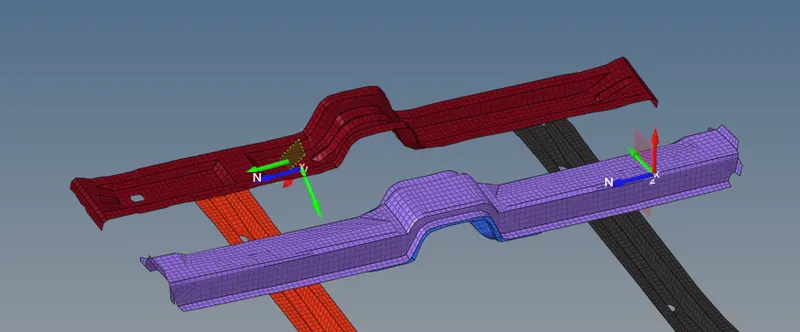
The sectional forces are applied to the cross members. where the forces are acting towards the normal plane. by selecting the three nodes i.e N1, N2, N3 we give the node id and create a frame in the solver with the help of three nodes that we have selected in the cross-section and create a set and then select the elements where the nodes got selected to cut the surface.
Intrusions:
To calculate the displacement of the B-Pillar, Hinge-Pillar, and the fuel tank we give the intrusions for the intrusions on the B-pillar, Hinge Pillar, and in the fuel tank region.
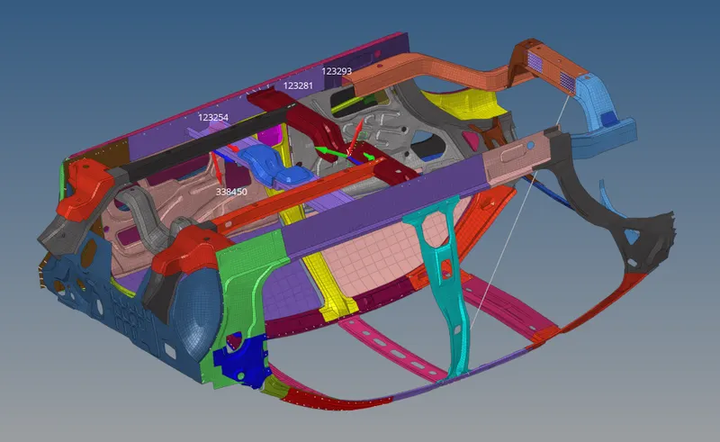
Here from the above figure, there are node id's which define their respective intrusions.
Node Id 123239 defines for the Fuel Tank.
Node Id 123281 defines for the B-Pillar.
Node Id 123254 defines for Hinge Pillar.
Node Id 338450 defines the Peak velocity.
Model Checker:
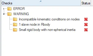
After running the model checker to ensure any errors before simulation. gone through some warnings which can be ignored and proceed for the simulation and if there are any errors we should auto-correct it.
After running the checks through the model checker there are some warnings related to the kinematic conditions and rigid bodies, which can be ignored.
Results:
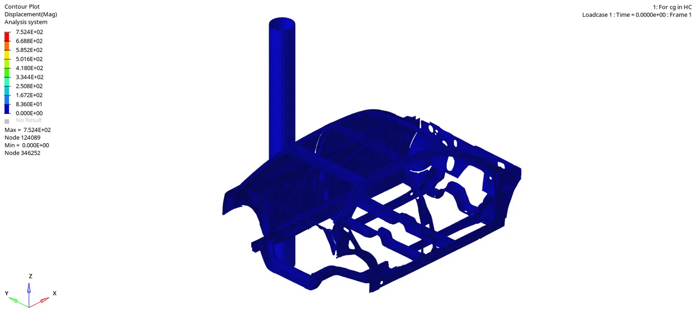
For Displacement:
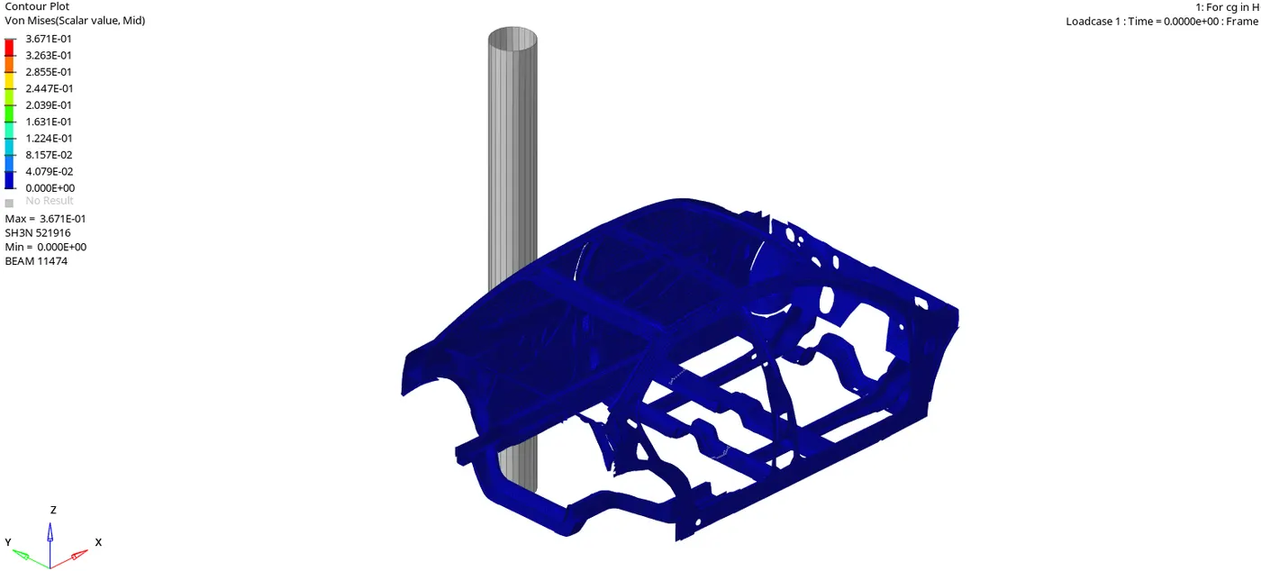
For Von mises stress:
Sectional Forces:
For Cross Members:
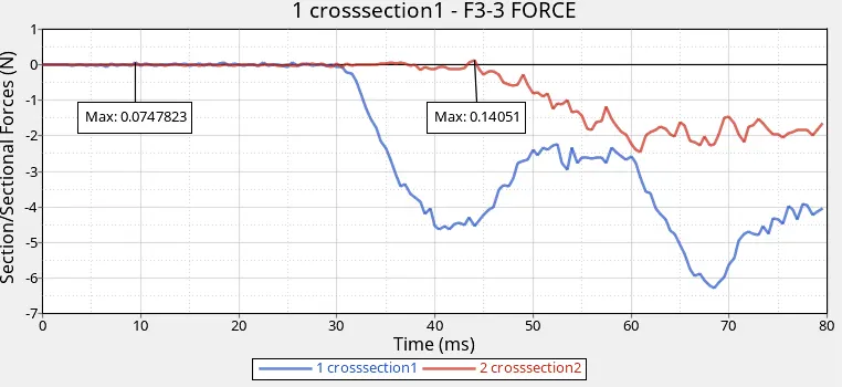
Here from the above sectional forces plotting.
- In this case, the force is acting on the z-direction which is a magnitude.
- The maximum force applied on the cross member-1 is 0.074 N at a point of 9 ms.
- The maximum force applied on the cross member-2 is 0.140 N at a point of 44 ms.
- Cross-member -2 has the maximum force compared to the cross member-1.
For Peak Velocity:
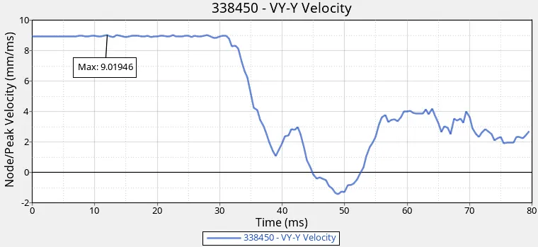
Here from the above peak velocity plotting.
- In this case, the maximum peak velocity was 9.01 mm/ms at a point of 11 ms.
- The velocity was constant till 30 ms and thereafter when the vehicle was in contact with the pole there was a decrease in the velocity as the vehicle was getting deformed.
Energies:
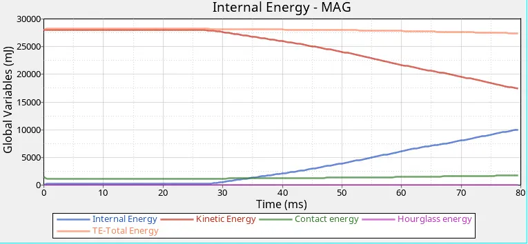
Here from the above energy plottings.
- As the Internal energy increases the kinematic energy decreases due to the conservation of the internal energy.
- When there is a collision with the pole the contact energy takes place from the initial to the final position.
- The Hourglass energy is zero as we have given the QEPH Recommended shell elements to avoid this curve.
- The total energy is the addition of all the energies i.e TE= IE+KE+CE+HE.
Intrusions:
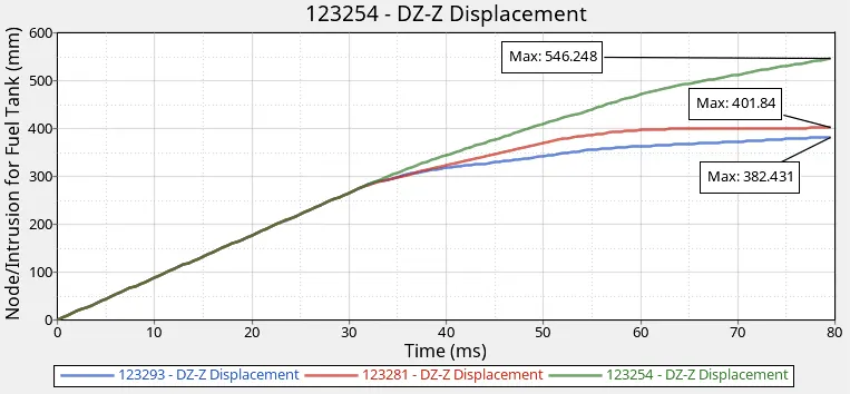
Here from the above intrusions plottings displacement of the fuel tank,b-pillar, and hinge pillar is measured through skew.
- Node= 123293 defines displacement of Fuel Tank whose maximum displacement is 382.4 mm at a point of 80 ms.
- Node= 123281 defines the displacement of the B-pillar whose maximum displacement is 401.84 mm at a point of 80 ms.
- Node= 123254 defines the displacement of the Hinge-pillar whose maximum displacement is 546.2 mm at a point of 80 ms.
- Compared to all the above nodes. Hinge Pillar has the maximum displacement than the Fuel Tank and B-Pillar.
What can help to reduce Fuel tank intrusion?
We can reduce the intrusion of the fuel tank by increasing the stiffness of the fuel tank region by assigning the additional thickness to it. which can be more flexible to resist the deformation during the crash.
Conclusion:
The side crash is carried out for the given model and identified the various load path members and sensitivity locations. This result is used to identify suitable design countermeasures to reduce occupant injuries and compartment intrusion.