Powertrain for aircraft in runways
OBJECTIVE: To design an electric powertrain with a suitable motor to fulfill its power rating and energy requirements with an aircraft towing application.
TEST CASES:
1) Search and list out the total weight of various types of aircraft.
2) Is there any difference between ground speed and airspeed?
3) Why is it not recommended to use aircraft engine power to move it on the ground at the Airport?
4) How an aircraft is pushed to the runway when it's ready to take off?
5) Learn about take-off power, tire design, rolling resistance, tire pressure, brake forces when landing.
6) With necessary assumptions, calculate the force and power required to push/pull an aircraft by a towing vehicle.
7) Design an electric powertrain with the type of motor, its power rating, and energy requirement to fulfill aircraft towing application. Estimate the duty cycle range to control the aircraft speed from zero to highest. Make all required assumptions. Prepare a table of assumed parameters. Draw a block diagram of the powertrain.
INTRODUCTION:
What is a Powertrain?
As the name suggests, the powertrain provides power to the vehicle. Powertrain refers to the set of components that generate the power required to move the vehicle and deliver it to the wheels.
Difference between Powertrains of EV's & ICE Vehicles
The powertrain of an electric vehicle is a simpler system, comprising of far fewer components than a vehicle powered by an internal combustion engine.
Main Components of an EV Powertrain
An EV powertrain has 60% fewer components than the powertrain of an ICE vehicle. Which is described below
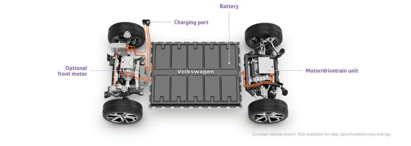
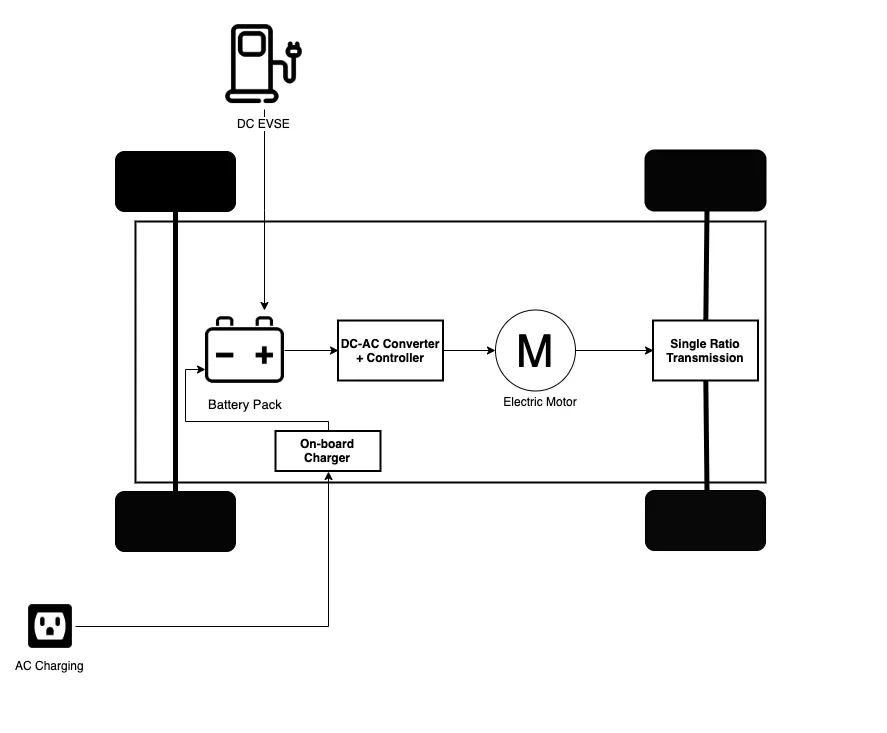
Battery Pack- The battery pack is made up of multiple Lithium-ion cells and stores the energy needed to run the vehicle. The battery pack provides direct current (DC) output.
DC - AC Converters: The DC Supplied by the battery pack is converted to AC and supplied to the electric motor. This power transfer is managed by a sophisticated motor control mechanism that controls the frequency and magnitude of the voltage supplied to the electric motor in order to manage the speed and acceleration as per the driver's instructions communicated via acceleration/brakes.
Electric Motor: Converts electrical energy to mechanical energy that is delivered to the wheels via single ratio transmission. Many EVs use a motor-generator that can perform regeneration as well.
On-board charger: Converts AC received through charge port to DC and controls the amount of current flowing into the battery pack.
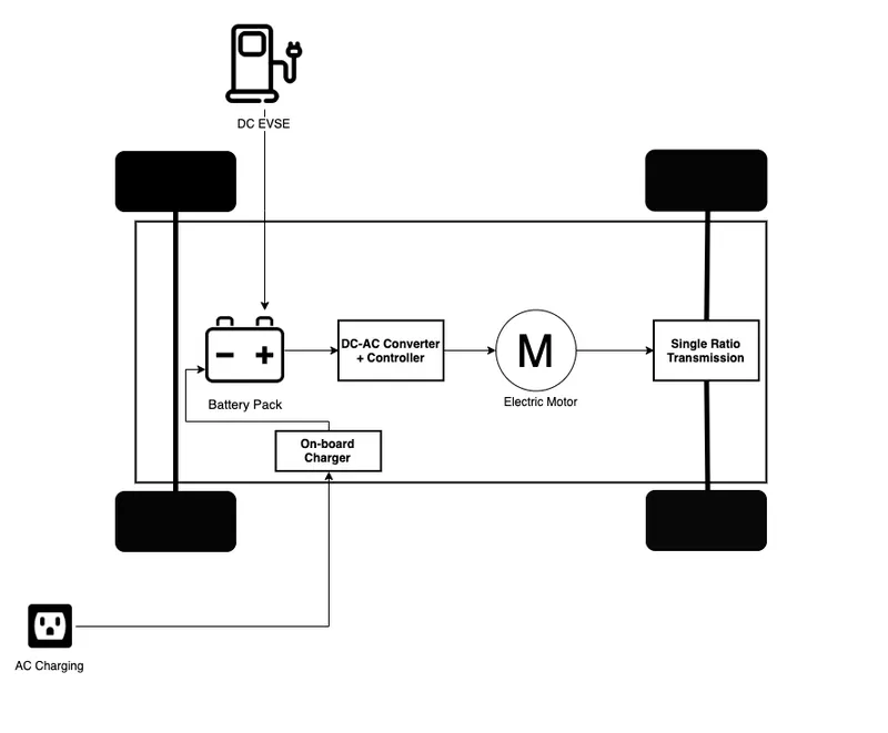
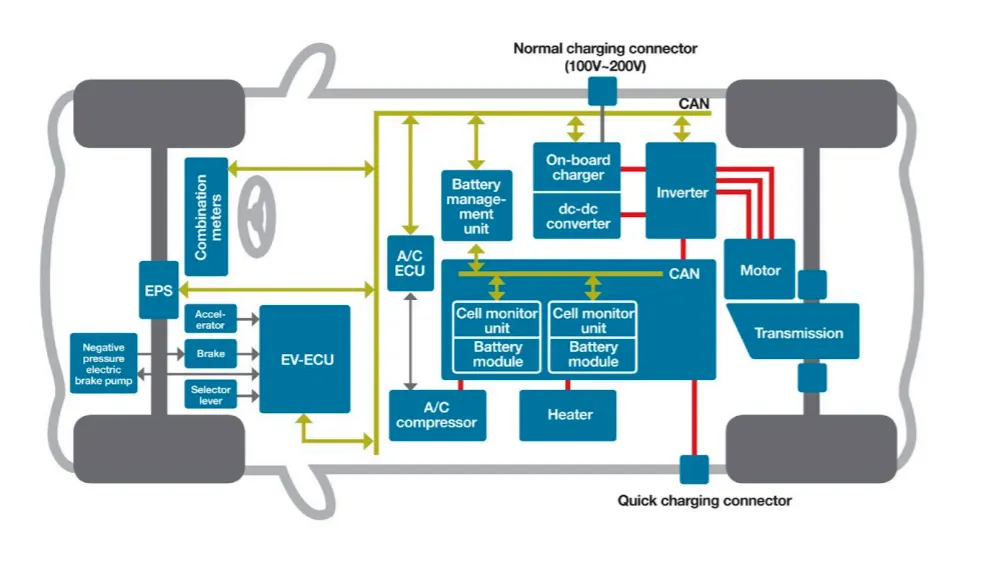
Apart from the above core parts, there are multiple hardware and software components in an EV powertrain. Electronic Control Units (ECUs) are basically software programs integrated with the powertrain components to help data exchange and processing. There are several small ECUs in an EV that perform specific functions. The communication between different ECUs in a vehicle is commonly carried over CAN Protocol. More examples of core ECUs are:
Battery Management System (BMS): A BMS continuously monitors the state of the battery and is responsible for taking necessary measures in case of a malfunction. BMS performs cell balancing to deliver maximum efficiency from the battery pack. It is responsible for communication with other ECUs and sensors as well as EVSEs to control the charging input, to check the current stage of charge and share data about battery specifications.
DC-DC Converter: A battery pack delivers a fixed voltage, but the requirement of different accessory systems (e.g wipers, lights, infotainment system, mirror control) in the EV would vary. The DC-DC converter helps distribute power to different systems by converting the output power from the battery pack to the expected level. After conversion, power is delivered to respective smaller ECUs via a wiring harness.
Thermal Management System: Responsible for maintaining optimum operating temperature range for powertrain components.
Body Control Module (BCM): The BCM is responsible for supervising and controlling the functions of electronic accessories such as power windows, mirrors, security, and vehicle access control.
PROCEDURE:
1) Search and list out the total weight of various types of aircrafts.
A brief description about these is below:
Manufacturer's Empty weight(MEW)
Also called Manufacturer's Weight Empty (MWE) or Licensed Empty Weight
It is the weight of the aircraft "as built" and includes the weight of the structure, power plant, furnishings, installations, systems and other equipment that are considered an integral part of an aircraft.
This excludes any baggage, passengers, or usable fuel2.
Zero-fuel weight (ZFW)
This is the total weight of the airplane and all its contents (including unusable fuel), but excluding the total weight of the usable fuel on board.
As a flight progresses and fuel is consumed, the total weight of the airplane reduces, but the ZFW remains constant.
Maximum zero fuel weight (MZFW) is the maximum weight allowed before usable fuel and other specified usable agents (engine injection fluid, and other consumable propulsion agents) are loaded.
Operating empty weight (OEW) (Roughly equivalent to basic empty weight on light aircraft)
It is the basic weight of an aircraft including the crew, all fluids necessary for operation such as engine oil, engine coolant, water, unusable fuel and all operator items and equipment required for flight but excluding usable fuel and the payload.
Payload
It is the carrying capacity of an aircraft. It includes cargo, people, extra fuel. In the case of a commercial airliner, it may refer only to revenue-generating cargo or paying passengers.
Maxium takeoff weight (MTOW)
This is the maximum weight at which the pilot of the aircraft is allowed to attempt to take off3.
Regulated takeoff weight(RTOW)
Depending on different factors (e.g. flap setting, altitude, air temperature, length of runway), RTOW or maximum permissible takeoff weight varies for each takeoff. It can never be higher than MTOW.
Maxium Loading weight (MLW)
This maximum weight at which an aircraft is permitted to land3.
The following image depicts takeoff weight components.
Maximum ramp weight (MRW)
It is also called maximum taxi weight (MTW)
It is the maximum weight authorized for maneuvering (taxiing or towing) an aircraft on the ground.
Aircraft gross weight
It is the total aircraft weight at any moment during the flight or ground operation. This decreases during flight due to fuel and oil consumption.
| Type | MTOW [kg] | MLW [tons] | TOR [m] | LR [m] | ICAO category | FAA category |
|---|---|---|---|---|---|---|
| Antonov An-225 | 640,000 | 591.7 | 3500 | Heavy | Super | |
| Scaled Composites Model 351 Stratolaunch | 589,670 | 3660 | Heavy | Super | ||
| Airbus A380-800[1][2][3] | 575,000 | 394 | 3100 | 1930 | Super | Super |
| Boeing 747-8F | 447,700 | 346.091 | 3100 | 1800 | Heavy | Heavy |
| Boeing 747-8 | 443,613 | 306.175 | 3100 | Heavy | Heavy | |
| Boeing 747-400ER | 412,770 | 295.742 | 3090 | Heavy | Heavy | |
| Antonov An-124-100M | 405,060 | 330 | 2520 | 900 | Heavy | Heavy |
| Boeing 747-400 | 396,900 | 295.742 | 3018 | 2179 | Heavy | Heavy |
| Lockheed C-5 Galaxy[4][5][6] | 381,000 | 288.417 | 2530 | 1494 | Heavy | Heavy |
| Boeing 747-200[7] | 377,840 | 285.700 | 3338 | 2109 | Heavy | Heavy |
| Boeing 747-300[7] | 377,840 | 260.320 | 3222 | 1905 | Heavy | Heavy |
| Airbus A340-500[8] | 371,950 | 240 | 3050 | 2010 | Heavy | Heavy |
| Airbus A340-600[8] | 367,400 | 256 | 3100 | 2100 | Heavy | Heavy |
| Boeing 777F | 347,800 | 260.816 | 2830 | Heavy | Heavy | |
| Boeing 777-300ER | 351,800 | 251.29 | 3100 | Heavy | Heavy | |
| Boeing 777-200LR | 347,450 | 223.168 | 3000 | Heavy | Heavy | |
| Boeing 747-100[7] | 340,200 | 265.300 | Heavy | Heavy | ||
| Airbus A350-1000 | 308,000 | 233.5 | Heavy | Heavy | ||
| Boeing 777-300 | 299,370 | 237.683 | 3380 | Heavy | Heavy | |
| Boeing 777-200ER | 297,550 | 213.00 | 3380 | 1550 | Heavy | Heavy |
| Airbus A340-300[8][9] | 276,700 | 190 | 3000 | 1926 | Heavy | Heavy |
| McDonnell Douglas MD-11 | 273,300 | 185 | 2990 | 1890 | Heavy | Heavy |
| Airbus A350-900 | 270,000 | 175 | 2670 | 1860 | Heavy | Heavy |
| Ilyushin Il-96M | 270,000 | 195.04 | 3115 | 2118 | Heavy | Heavy |
| McDonnell Douglas DC-10 | 256,280 | 183 | 2990 | 1890 | Heavy | Heavy |
| Boeing 787-9[10] | 254,000 | 192.777 | 2900 | Heavy | Heavy | |
| Boeing 787-10[10] | 254,000 | 201.849 | Heavy | Heavy | ||
| Airbus A340-200[8][11] | 253,500 | 181 | 2990 | Heavy | Heavy | |
| Ilyushin IL-96-300 | 250,000 | 175 | 2600 | 1980 | Heavy | Heavy |
| Airbus A330-300[12][13] | 242,000 | 185 | 2500 | 1750 | Heavy | Heavy |
| Airbus A330-200[12][13] | 242,000 | 180 | 2220 | 1750 | Heavy | Heavy |
| Lockheed L-1011-500 | 231,300 | 166.92 | 2636 | Heavy | Heavy | |
| Boeing 787-8[10] | 228,000 | 172.365 | 3300 | 1695 | Heavy | Heavy |
| Lockheed L-1011-200 | 211,400 | Heavy | Heavy | |||
| Ilyushin IL-86 | 208,000 | 175 | Heavy | Heavy | ||
| Boeing 767-400ER | 204,000 | 158.758 | 3414 | Heavy | Heavy | |
| Airbus A300-600R[14] | 192,000 | 140 | 2385 | 1555 | Heavy | Heavy |
| Boeing 767-300ER | 187,000 | 136.08 | 2713 | 1676 | Heavy | Heavy |
| Concorde | 185,000 | 111.1 | 3440 | 2220 | Heavy | Heavy |
| Airbus A300-600[14] | 163,000 | 138 | 2324 | 1536 | Heavy | Heavy |
| Boeing 767-300 | 159,000 | 136.078 | 2713 | 1676 | Heavy | Heavy |
| Airbus A310-300[14] | 157,000 | 124 | 2290 | 1490 | Heavy | Heavy |
| Vickers VC10 | 152,000 | 151.9 | Heavy | Heavy | ||
| Boeing 707-320B[15] | 151,000 | 97.5 | Heavy | Heavy | ||
| Boeing 707-320C[15] | 151,000 | 112.1 | Heavy | Heavy | ||
| Douglas DC-8-61 | 147,000 | Heavy | Heavy | |||
| Airbus A310-200[14] | 142,000 | 123 | 1860 | 1480 | Heavy | Heavy |
| Airbus A400M | 141,000 | 122 | 980 | 770 | Heavy | Heavy |
| Douglas DC-8-32 | 140,000 | Heavy | Heavy | |||
| Douglas DC-8-51 | 125,000 | Medium | Large | |||
| Boeing 757-300 | 124,000 | 101.6 | 2550 | 1750 | Medium | Large |
| Boeing 707-120B[15] | 117,000 | 86.3 | Medium | Large | ||
| Boeing 757-200 | 116,000 | 89.9 | 2347 | 1555 | Medium | Large |
| Boeing 720B[16] | 106,000 | 79.5 | Medium | Large | ||
| Boeing 720[16] | 104,000 | 79.5 | Medium | Large | ||
| Tupolev Tu-154M | 104,000 | 80 | Medium | Large | ||
| Tupolev Tu-204SM | 104,000 | 87.5 | 2250 | Medium | Large | |
| Convair 880 | 87,500 | Medium | Large | |||
| Boeing 737-900 | 85,000 | 66.36 | 2500 | 1704 | Medium | Large |
| Boeing 737-900ER | 85,000 | 71.35 | 2804 | 1829 | Medium | Large |
| Boeing 727-200 Advanced[17] | 84,000 | 70.1 | Medium | Large | ||
| Airbus A321-100[18] | 83,000 | 77.8 | 2200 | 1540 | Medium | Large |
| Boeing 737-800 | 79,000 | 65.32 | 2308 | 1634 | Medium | Large |
| Boeing 727-200[17] | 78,000 | 68.1 | Medium | Large | ||
| McDonnell-Douglas MD-83 | 73,000 | 63.28 | Medium | Large | ||
| Boeing 727-100[17] | 72,500 | 62.4 | Medium | Large | ||
| Boeing 727-100C[17] | 72,500 | 62.4 | Medium | Large | ||
| McDonnell-Douglas MD-90-30 | 71,000 | 64.41 | 2165 | 1520 | Medium | Large |
| de Havilland Comet 4 | 70,700 | Medium | Large | |||
| Boeing 737-700 | 70,000 | 58.06 | 1921 | 1415 | Medium | Large |
| Airbus A320-100[18] | 68,000 | 66 | 1955 | 1490 | Medium | Large |
| Boeing 737-400 | 68,000 | 54.9 | 2540 | 1540 | Medium | Large |
| de Havilland Comet 3 | 68,000 | Medium | Large | |||
| Boeing 377 | 67,000 | Medium | Large | |||
| Boeing 737-600 | 66,000 | 54.66 | 1796 | 1340 | Medium | Large |
| Airbus A220-300 | 65,000 | 57.61 | 1890 | 1494 | Medium | Large |
| Hawker Siddeley Trident 2E | 65,000 | Medium | Large | |||
| Airbus A319[18] | 64,000 | 62.5 | 1850 | 1470 | Medium | Large |
| Boeing 737-300 | 63,000 | 51.7 | 1939 | 1396 | Medium | Large |
| Boeing 737-500 | 60,000 | 49.9 | 1832 | 1360 | Medium | Large |
| Airbus A220-100 | 59,000 | 50.80 | 1463 | 1356 | Medium | Large |
| Airbus A318[18] | 59,000 | 57.5 | 1375 | 1340 | Medium | Large |
| Boeing 717-200HGW | 55,000 | 47.174 | 1950 | Medium | Large | |
| Douglas DC-7 | 55,000 | Medium | Large | |||
| de Havilland Comet 2 | 54,000 | Medium | Large | |||
| Boeing 717-200BGW | 50,000 | 46.265 | 1950 | Medium | Large | |
| de Havilland Comet 1 | 50,000 | Medium | Large | |||
| Douglas DC-6A | 48,600 | Medium | Large | |||
| Douglas DC-6B | 48,500 | Medium | Large | |||
| Embraer 190[19] | 48,000 | 43 | 2056 | 1323 | Medium | Large |
| Caravelle III | 46,000 | Medium | Large | |||
| Fokker 100 | 46,000 | 39.95 | 1621 | 1350 | Medium | Large |
| Douglas DC-6 | 44,000 | Medium | Large | |||
| Avro RJ-85 | 42,000 | 36.74 | Medium | Large | ||
| Handley Page Hermes | 39,000 | Medium | Large | |||
| Embraer 175[20] | 37,500 | 32.8 | 2244 | 1304 | Medium | Large |
| Bombardier CRJ900[21] | 36,500 | 33.345 | 1778 | 1596 | Medium | Large |
| Embraer 170[22] | 36,000 | 32.8 | 1644 | 1274 | Medium | Large |
| Bombardier CRJ700 | 33,000 | 30.39 | 1564 | 1478 | Medium | Large |
| Douglas DC-4 | 33,000 | Medium | Large | |||
| Vickers Viscount 800 | 30,400 | Medium | Large | |||
| Bombardier Q400 | 28,000 | 28.01 | 1219 | 1295 | Medium | Large |
| Bombardier CRJ200 | 23,000 | 21.319 | 1918 | 1479 | Medium | Large |
| ATR 72-600 | 22,800 | 22.35 | 1333 | 914 | Medium | Large |
| Saab 2000 | 22,800 | 21.5 | 1300 | Medium | Large | |
| Embraer ERJ 145 | 22,000 | 19.3 | 2270 | 1380 | Medium | Large |
| ATR 42-500 | 18,600 | 18.3 | 1165 | 1126 | Medium | Small |
| Saab 340 | 13,150 | 12.930 | 1300 | 1030 | Medium | Small |
| Embraer 120 Brasilia | 11,500 | 11.25 | 1560 | 1380 | Medium | Small |
| BAe Jetstream 41 | 10,890 | 10.570 | 1493 | 826 | Medium | Small |
| Learjet 75[23] | 9,752 | 8.709 | 1353 | 811 | Medium | Small |
| Pilatus PC-24[24] | 8,300 | 7.665 | 893 | 724 | Medium | Small |
| Embraer Phenom 300[25] | 8,150 | 7.65 | 956 | 677 | Medium | Small |
| Beechcraft 1900D | 7,765 | 7.605 | 1036 | 853 | Medium | Small |
| Cessna Citation CJ4[26] | 7,761 | 7.103 | 1039 | 896 | Medium | Small |
| de Havilland Hercules | 7,000 | Medium | Small | |||
| Embraer Phenom 100 | 4,800 | 4.43 | 975 | 741 | Light | Small |
2) Is there any difference between ground speed and air speed?
The difference between ground speed and airspeed is caused by the influence of winds on the overall velocity of the aircraft
The relationship between ground speed, airspeed, and wind speed can be written in the following form:

If the wind moves in the same direction as the aircraft, the term Vwind will have a positive sign. If the wind blows in the opposite direction as the plane's motion, Vwind will be a negative number.
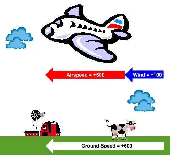
Effect of tailwind on ground speed
This important distinction between ground speed and airspeed can be better understood by observing the above example. Let's assume that the aircraft's cruise speed, or its speed relative to the local air, is 500 mph. However, the air itself is not motionless but moves at a speed of 100 mph in this example. Let us also assume that the plane is traveling in the same direction as the wind such that it experiences a tailwind of 100 mph. Since the wind and vehicle both move in the same direction, their velocities add together, and the ground speed becomes 600 mph.
Now let's look at the opposite problem, as illustrated below. In this example, the wind still blows at the same speed with respect to the ground, but its direction is reversed. Now the plane travels against the wind and experiences a headwind of 100 mph. The aircraft is still moving at the same cruise speed of 500 mph with respect to the air, but the difference in the direction of motion of the air means that the wind speed must be subtracted from the plane's airspeed in order to determine the ground speed. The ground speed now becomes only 400 mph.
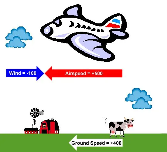
Effect of headwind on ground speed
In these examples, we assumed some round numbers to simplify the explanation. Let us now consider the case described in the question in greater detail. A Boeing 777 has a typical cruise speed of about 560 mph (900 km/h) at an altitude of 35,000 ft (10,675 m). However, the in-flight entertainment system indicated a ground speed of over 700 mph (1,125 km/h). According to the equation shown above, the plane must have encountered a tailwind of at least 140 mph (225 km/h) to make up the difference. While such a wind speed is indeed larger than normal, it is not unheard of at high altitude. Head and tailwinds of around 60 to 80 mph (95 to 130 km/h) are pretty common at these altitudes, and wind speeds approaching 300 mph (480 km/h) are even encountered on occasion in a region known as the jetstream.
Nevertheless, we have pointed out that Mach number is independent of ground speed or wind speed and depends only on the plane's speed relative to the local airflow. Mach number is defined as the ratio of airspeed (V) to the speed of sound (a) at that altitude. m=v/a
According to the standard atmosphere model. Even if the plane's ground speed is over 700 mph, however, its airspeed will still be only 560 mph. As a result, the aircraft's Mach number turns out to be about 0.84, or 84% of the speed of sound. In other words, the Boeing 777 never flew faster than the speed of sound during your flight.
It is important to understand this distinction between airspeed and ground speed for other reasons beyond those specifically addressed in this question. The entire field of aerodynamics concerns the forces generated on a body as it moves through some fluid, like air. Most notably, a wing can only create lift if it is moving through the air, or air is moving over it. We can see this dependence most clearly in the lift equation that tells us the lift force depends on the square of the vehicle's speed relative to the air.
Note that I said relative to the air, for the direction the wind is blowing can help or hinder a wing in generating lift. This behavior is particularly important during takeoff and landing. Consider, for example, a typical commercial airliner with a takeoff speed of 180 mph (290 km/h). In other words, the plane would need to accelerate down the runway and achieve a ground speed of 180 mph in order to become airborne on a windless day. Now, consider a wind of 25 mph (40 km/h) blowing along the runway. Let's first assume the wind is a tailwind blowing in the same direction as the aircraft as it moves down the runway. We can now solve for the plane's airspeed using the relationship:

Since the tailwind subtracts from the ground speed of 180 mph, the plane's airspeed is only 155 mph (250 km/h). This speed is insufficient to lift off, so the plane needs a longer runway to make up that extra 25 mph and generate the lift needed to takeoff. Conversely, if that wind is a headwind, it adds to the ground speed. Now the plane can takeoff on a shorter runway since it only needs to accelerate to 155 mph. The extra 25 mph is provided by the wind blowing over the wing to give the plane its needed airspeed of 180 mph.
3) Why is it not recommended to use aircraft engine power to move it on the ground at the Airport?
It is not recommended to use aircraft engine power to move it on the ground at airport because there are certain extreme cautions for everything around us like.
- Applying Thrust (gas) can create a blast behind each engine.
- People,equipment,and anything else in the way can be injured or damaged from the jet blast.
- Before we apply power to the engines the areas in front of a each engine are like another super critical factor that must be carefully negotiated.
- The immediate area in front of a jet engine creates an area where people and equipment can be sucked in to the engine if anything is too close to the intake.
- So to avoid all such extreme cautions it is not recommended to use aircraft engine power to move it on the ground at the airport.
4) How an aircraft is pushed to runway when its ready to take off?
Solution:
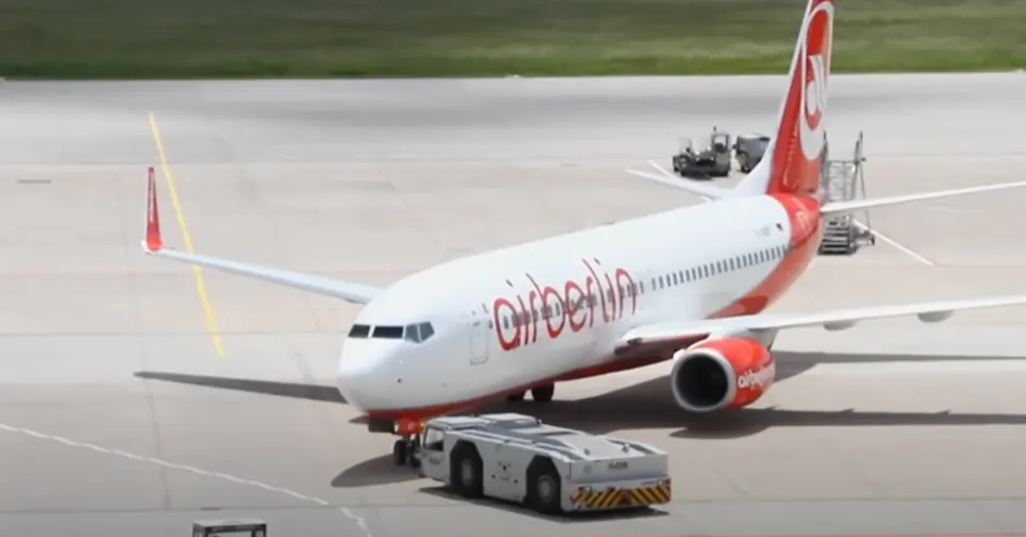
The aircraft is pushed to runway through pushback when it is ready to take off
Take off performance can be predicted using a simple measure of the acceleration of the aircraft along the runway based on force equilibrium.
The forces involved will be,
T – Thrust of propulsion system pushing aircraft along runway.
D – Aerodynamic Drag of vehicle resisting the aircraft motion.
F – Rolling resistance friction due to the contact of wheels or skids on the ground.
During take-off run the imbalance in these forces will produce an acceleration along the runway.
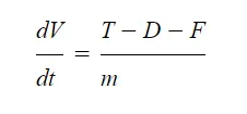
where dV/dt is the acceleration along the runway and m is the mass of the vehicle.
Whereas, Power = (T-D-F)V
ii) TYRE DESIGN:
When it comes to safety, tyres are one of the most important components of aircraft. They help to absorb the shock of landing and provide cushioning. It also provides the necessary traction for braking and stopping of an aircraft.
An aircraft tyre is designed to withstand extremely heavy loads while landing, take off, taxing and parking. The number of wheels required for aircraft increases with the weight of the aircraft, as the weight of the aeroplane needs to be distributed more evenly.
A Boeing 737NG & 737MAX uses 6 wheels, Boeing 787 uses 10 wheels, Boeing 777 uses 14 wheels and Airbus A380 uses 22 wheels. Aircraft tyres work under extreme conditions, carrying up to 340 tons and accelerating at over 250 km/hour at takeoff, in addition to enduring varied environmental stress when in flight and taxiing.
Carcass plies are used to form the tire. They are sometimes called casing plies. An aircraft tyre is constructed for the purpose it serves.
- They support the weight of an aircraft while it is on the ground.
- It also provides the necessary traction for braking and stopping of an aeroplane.
- Tyre also helps to absorb the shock of landing and provide cushioning the roughness of takeoff, roll-out, and taxi operations.
Unlike an automobile or truck tyre, it does not have to carry a load for a long period of continuous operation. However, an aircraft tyre absorbs the high impact loads of landing and also it’s operating at high speeds for a short time when required.
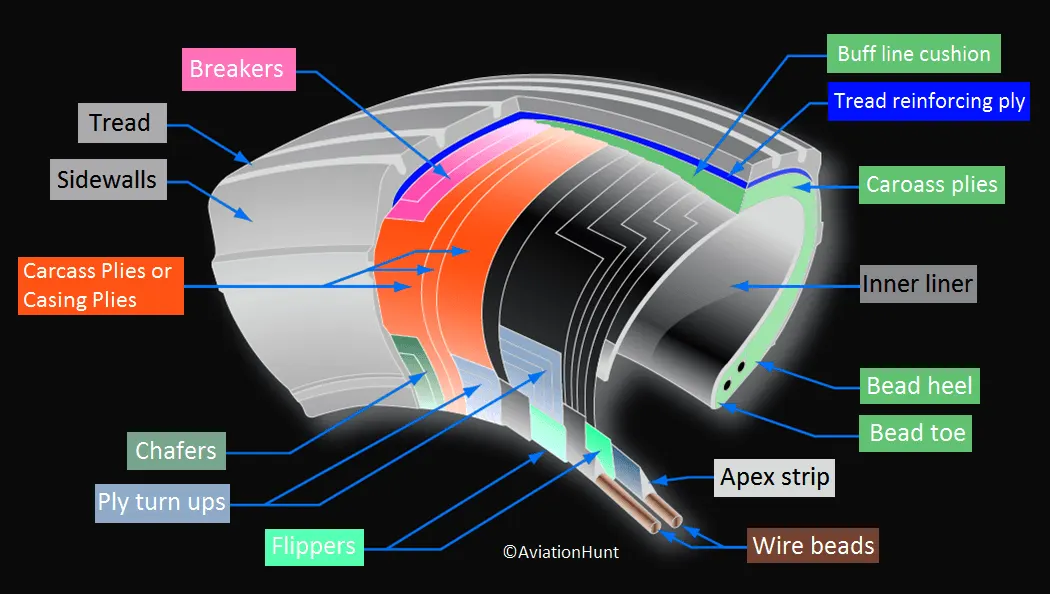
Let’s go through some technical aspects of the tyre.
Retreading – Retreading is methods of restoring a worn tyre by renewing the tread area or by renewing the tread area plus one or both sidewalls. Repairs are included in the tyre retreading process.
Load Rating – Load rating is the maximum permissible load at a specified inflation pressure.
Ply Rating – Ply Rating is used to identify the maximum recommended load rating and inflation pressure for a specified tyre. It is an index of tyre strength.
Speed Rating – The speed rating is the maximum takeoff speed to which the tyre has been tested.
Skid Depth – Skid depth is the distance between the tread surface and the deepest groove as measured in the mould.
Aircraft tyres must have an approved speed and load rating and have sufficient clearance when retracted through landing gear to allow for tyre growth. Tyre growth is the increase in the size of the tyre due to centrifugal forces at high speed.
Aircraft tyres may be Tube-type or Tubeless
Tubeless tyres are more advantageous over tube-type. There is no longer the use of tube-type tyre in recent aviation. Nowadays all airliners are using tubeless tyres. Tubeless that are meant to be used without a tube has the word TUBELESS on the sidewall of the tyre.
Aircraft tyres may be Radial or Bias
Almost all airliners are using Radial tyre. Bias is an older design, and it’s mainly used for road vehicles. Radial tyres have the word RADIAL on the sidewall. Radial tires are more expensive than bias-ply tyres. Radial tires are in demand because of their lower life cycle cost and long term value.
Are aviation tyres are conductive?
Yes, Today’s tyres are conductive. Aircraft tyres are manufactured with tread rubber with conducting compounds to permit earthing of static charges.
In early days when tyres were not sufficiently conductive, aircraft used to have a conductive strip hanging down from the axle of the landing gear. Upon landing, this strip would be the first part of the aircraft to touch the earth. This discharges any static electricity accumulated on the outer surfaces of the aircraft. Now you don’t see them any more.
What is the purpose of Chines in aviation tyre
Chines are also called deflectors. Chine tyre used on the nose wheel of aircraft, specially fuselage-mounted jet engines. It diverts runway water away from the engine inlets.
Chines are circumferential protrusions that are moulded into the sidewall of nose tyres that deflect water sideways to help reduce excess water ingestion into the engines. Tyres may have chines on one or both sides, depending on the number of nose tyres on the aircraft.
Aircraft Tyre Standards
Each tyre manufacturer produces their own designs of the tyre with different tread patterns, wear patterns, wear limits etc, and in some cases, different names for the same part of the tyre. But all tyres must meet the approved standards before being accepted by the FAA or CAA.
All commercial aircraft tyres approved under FAA Requirement Technical Standard Order (TSO) C62. A TSO is a minimum performance standard for specified materials, parts, and appliances used on civil aircraft.
iii) ROLLING RESISTANCE:
Rolling resistance is the force resisting the motion when a body (such as a ball, tire, or wheel) rolls on a surface.
Rolling resistance can be seen in the aircraft when the aircrat Takes off from the runway and while landing at the runway with the help of their wheels.
The rolling resistance can be expressed as
Fr = c W
where
Fr = rolling resistance or rolling friction
c = rolling resistance coefficient - dimensionless (coefficient of rolling friction - CRF)
W = m ag
= normal force - or weight - of the body
m = mass of body (kg, lb)
ag = acceleration of gravity (9.81 m/s2, 32.174 ft/s2)
The rolling resistance can alternatively be expressed as
Fr = cl W / r
where
cl = rolling resistance coefficient - dimension length (coefficient of rolling friction) (mm, in)
r = radius of wheel (mm, in)
Rolling Coefficients
The rolling coefficients for air filled tires on dry roads can be estimated
c = 0.005 + (1 / p) (0.01 + 0.0095 (v / 100)2)
where
c = rolling coefficient
p = tire pressure (bar)
v = velocity (km/h)
iv) TYRE PRESSURE :
Aircraft tires generally operate at high pressures, up to 200 psi (14 bar; 1,400 kPa) for airliners, and even higher for business jets.
The main landing gear on the concorde was typically inflated to 232 psi (16.0 bar), whilst its tail bumper gear tires were as high as 294 psi (20.3 bar). The high pressure and weight load on the Concorde tyres were a significant factor in the loss of Air france flight 4590
Tests of airliner aircraft tires have shown that they are able to sustain pressures of maximum 800 psi (55 bar; 5,500 kPa) before bursting. During the tests the tires have to be filled with water, to prevent the test room being blown apart by the energy that would be released by a gas when the tire bursts.
Aircraft tires are usually inflated with nitrogen to minimize expansion and contraction from extreme changes in ambient temperature and pressure experienced during flight. Dry nitrogen expands at the same rate as other dry atmospheric gases (normal air is about 80% nitrogen), but common compressed air sources may contain moisture, which increases the expansion rate with temperature.
The requirement that an inert gas, such as nitrogen, be used instead of air for inflation of tires on certain transport category airplanes was prompted by at least three cases in which the oxygen in air-filled tires combined with volatile gases given off by a severely overheated tire and exploded upon reaching auto ignitation temperature The use of an inert gas for tire inflation will eliminate the possibility of a tire explosion.
v) BRAKE FORCE WHEN LANDING :
Aircraft brakes stop a moving aircraft by converting its kinetic energy to heat energy by means of friction between rotating and stationary discs located in brake assemblies in the wheels. Brakes provide this critical stopping function during landings to enable airplanes to stop within the length of the runway.
The following braking devices are used to decelerate the aircraft until it stops:
- Ground spoilers;
- Wheel brakes (including anti-skid systems and autobrake systems)and,
- Thrust-reverser
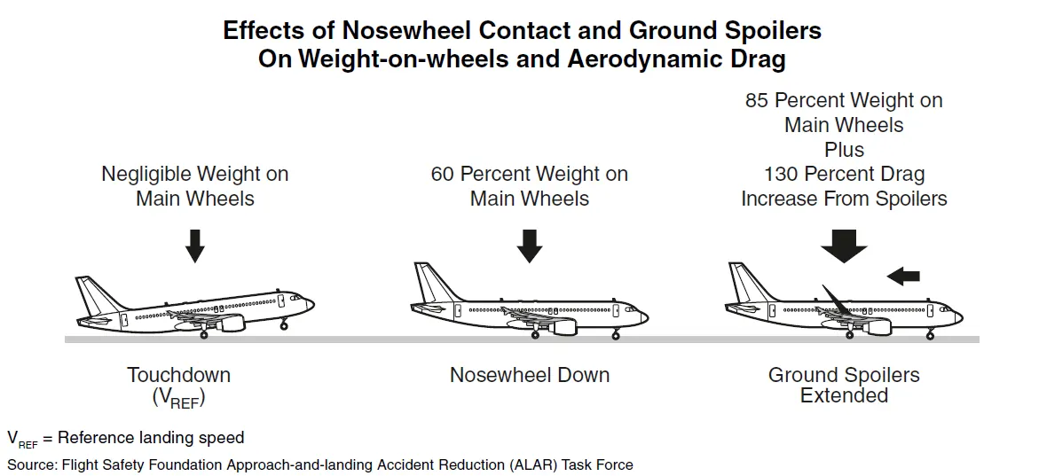
Ground Spoilers
Ground spoilers usually deploy automatically (if armed) upon main-landing-gear touchdown or upon activation of thrust reversers.
Ground spoilers provide two aerodynamic effects:
- Increased aerodynamic drag, which contributes to aircraft deceleration; and,
- Lift-dumping, which increases the load on the wheels and, thus, increases wheel-brake efficiency
Wheel Brakes
Braking action results from the friction force between the tires and the runway surface.
The friction force is affected by:
- Aircraft speed;
- Wheel speed (i.e., free-rolling, skidding or locked);
- Tire condition and pressure (i.e., friction surface);
- Runway condition (i.e., runway friction coefficient);
The load applied on the wheel
Braking force is equal to the load applied on the wheel multiplied by the runway friction coefficient.
Anti-skid systems are designed to maintain the wheel-skidding factor (also called the slip ratio) near the point providing the maximum friction force, which is approximately 10 percent on a scale from zero percent (free-rolling) to 100 percent (locked wheel),
Autobrake systems are designed to provide a selectable deceleration rate, typically between three knots per second and six knots per second
When a low autobrake deceleration rate (referred to hereafter as a “LOW” mode) is selected, brake pressure is applied usually after a specific time delay to give priority to the thrust-reverser deceleration force at high airspeed.
Thrust Reversers
Thrust reversers provide a deceleration force that is independent of runway condition.
Thrust-reverser efficiency is higher at high airspeed therefore, thrust reversers must be selected as early as possible after touchdown (in accordance with standard operating procedures).
Thrust reversers should be returned to reverse idle at low airspeed (to prevent engine stall or foreign object damage) and stowed at taxi speed
Nevertheless, maximum reverse thrust can be maintained to a complete stop in an emergency.
6) With necessary assumptions, calculate the force and power required to push / pull an aircraft by a towing vehicle.
Here with the certain assumptions
The forces that are acting on the aircraft are
i) Rolling Resistence
ii) Drag Force
i) Rolling Resistence for the Aircraft
Now, Here the Rolling resistence be
Fr = c. mr. ag
Here from the above formula
Let,
Fr = Rolling resistence
c = coefficient of rolling resistence (0.005)
mr = rolling mass (50000 kg)
ag = Acceleration of gravity
Now Substituting the values in the above formula gives us the Rolling resistence of the Aircraft
Fr = 0.005(50000 kg)(9.81 m/s^2)
Therefore the Rolling resisrence of the aircraft Fr = 2452.5 N
Rolling Resistence for the Towing Vehicle
Now let us calculate the rolling resistence for the Towing Vehicle
Fr = c. mr. ag
Fr = 0.002(78000 kg)(9.81 m/s^2)
Therefore the Rolling resisrence of the Towing vehicle Fr = 1530.36 N
ii) Drag Force
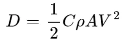
Where,
D = Drag force
C = Drag Coefficient ( 0.22)
V = Velocity of Towing Vehicle (5 m/s)
A = Frontal area (2)
Now Substituting the assumed values in the above formula gives us the Drag force of the Towing vehicle
Drag Force = (0.22*1.25*2*5*5)
= 6.87 N
Therefore the Drag force is = 6.87 N
Now to get the total force to push the aircraft by the towing vehicle
we add the Rolling resistence of the Aircraft + Rolling resistence of Towing Vehicle + Drag Force
= 2452.2 N + 1530.36 N + 6.87 N
Therefore the Total force required to a towing vehicle to push the aircraft is = 3989.73 N
Torque Required with the wheels of towing vehicle to push the aircraft
Torque = force x radius
assuming the radius of the wheels = 0.4572 m
= 3989.73 * 0.4572
Torque = 1824.10 Nm
Therefore the Totque required to the towing vehicle to push the aircraft = 1824.10 Nm
Power required to the towing vehicle to pull the aircraft
In this case, Power = force * velocity
= 3989.73 * 5.0
= 19.94*10^3 W
= 19.94 kW
Therefore the power required for the towing vehicle to pull the aircraft = 19.94 kW
7) Design an electric powertrain with type of motor, it’s power rating, and energy requirement to fulfill aircraft towing application. Estimate the duty cycle range to control the aircraft speed from zero to highest. Make all required assumptions. Prepare a table of assumed parameters. Draw a block diagram of powertrain.
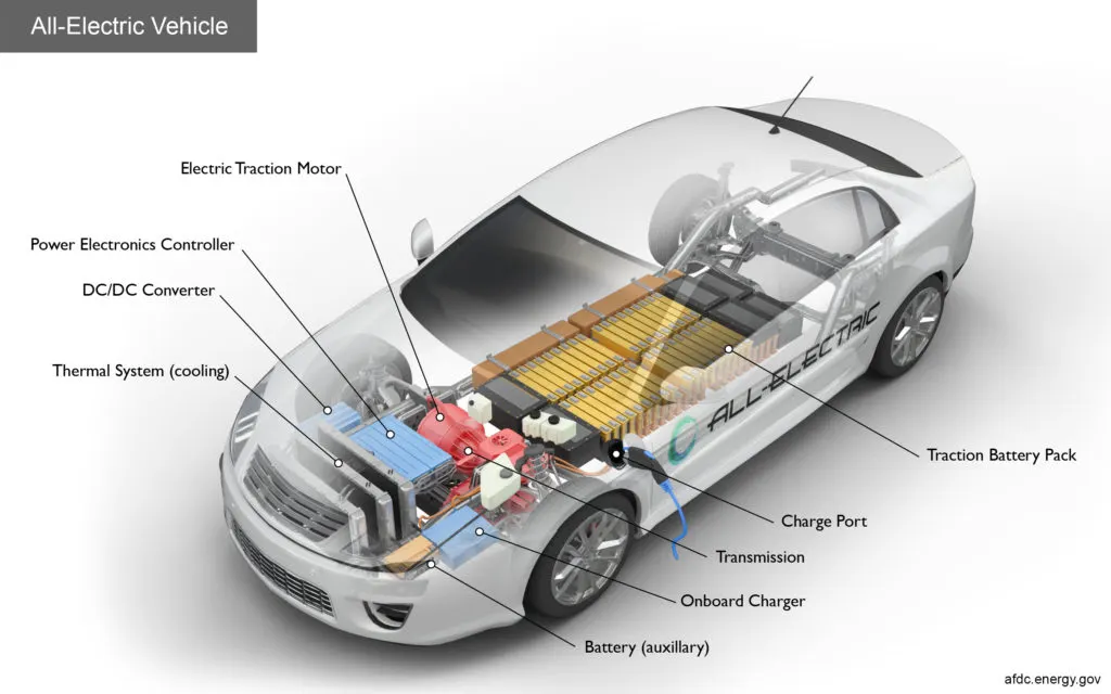
Main Components of an EV Powertrain
An EV powertrain has 60% fewer components than the powertrain of an ICE vehicle. The components are described below.
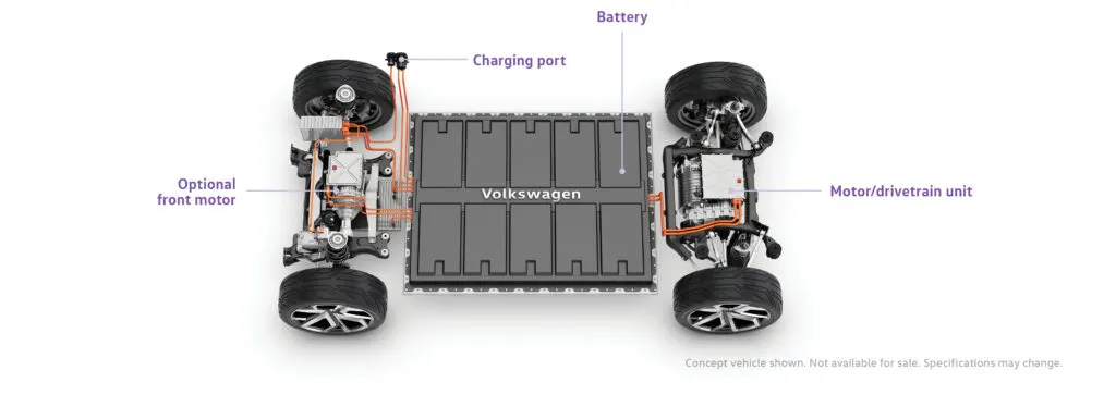
Battery Pack – The battery pack is made up of multiple Lithium-ion cells and stores the energy needed to run the vehicle. Battery packs provide direct current (DC) output.
DC-AC Converter – The DC supplied by battery pack is converted to AC and supplied to the electric motor. This power transfer is managed by a sophisticated motor control mechanism (also referred to as Powertrain Electronic Control Unit) that controls the frequency and magnitude of the voltage supplied to the electric motor in order to manage the speed and acceleration as per driver’s instructions communicated via acceleration/brakes.
Electric Motor – Converts electrical energy to mechanical energy, that is delivered to the wheels via single ratio transmission. Many EVs use motor generators that can perform regeneration as well.
On-board Charger – Converts AC received through charge port to DC and controls the amount of current flowing into the battery pack.
Starting with the Motor
i) In Motor Design :
Assuming
Type of Motor = BLDC Motor
Rated Power = 20-25 kW
Peak Power = 50 kW
Speed = 3200 - 5000 rpm
Rated Torque = 80 Nm
Peak Torque = 160 Nm
Efficiency = > 80 %
ii) In Power Rating :
The rated power of the Motor is 25kW and the peak power of the motor is double the rated power of the motor which is 50kW
The Converter used in this is DC - AC Converter
Assuming the Input Voltage = 349 V
and the Input Current as = 70 A
Now, Power Input = Voltage x current
= 349 x 70
= 24.30 kW
iii) In Energy Requirements :
The Energy requirement for an EV similar to the Towing vehicle to Push/Pull the aircraft is calculated on the Basis of Time
Let, Energy = Power x Time taken by the towing vehicle to push/pull the aircraft
We know that Power is = 24.30 kW
Time Taken by the Towing vehicle to push/pull the aircraft = 15 Minutes
So, Energy = 24.30 x 15 x 60
= 21870 KJ
= 6.075 kW
Therefore power required for one single towing is = 6.075 kW
iv) Duty Cycle :
Here in this case the Duty cycle of the electric power train is calculated by the output power by the input power.
by this we get the efficiency of the duty cycle
So here in this case,
Duty Cycle = Output Power / Input Power
We Know that,
Output Power as = 19.94 kW
Input Power as = 24.30 kW
Then the Duty Cycle is = 19.94 / 24.30
= 0.82 %
Therefore the Efficiency of the Duty cycle that we get for this electric power train is = 0 to 0.82 %
v) BLOCK DIAGRAM OF THE POWERTRAIN :
CONCLUSION: Therefore the design of an electric powertrain with a suitable motor has fulfilled its power rating and energy requirements with an aircraft towing application by estimating the duty cycle range to control the aircraft speed from zero to the highest.