Roof Crash Test Analysis on a Neon BIW(Body in White) by Using Crashworthiness and RADIOSS
Aim:
To Import
• Car
• Impactor
To Transforms
• This will require (in order)
• A 180° rotation about the global z-axis with the point opposite to C as the base point
• A 5° rotation about the axis through axis AB
• A 25° rotation about the axis through axis AC
• A translation to put point A at global ( -3500.00, 584.822, 1343.06)
Creating Interfaces
• Create a Type 7 contact interface between the impactor and the car
• choose an appropriate stiffness definition
• choose an appropriate minimum gap
• change the coefficient of friction to 0.2
• choose the appropriate friction penalty formulation
• Save the data from the interface to the time history file.
Creating Boundary condition
keep the suspension shock tower nodes locked in Z.
Giving Impactor Boundary Conditions
• The impactor assembly contains a spring attached for stability. Create a BCS
collector to fix the free end of the spring.
• Create a moving SKEW to define the direction normal to the impactor’s
face.
• Create a BCS collector to guide the master node of the impactor rigid body
so that it is free to translate normal to the face of the impactor, but is fixed
in all other DOFs.
Imposed Displacement
• Impose the velocity of the impactor starting from 0 mm/s at t = 0. The
displacement of the impactor should be 200 mm @ 200 ms.
• Avoid abrupt changes in the acceleration of the impactor.
Control Cards
• /ANALY card
• /DEF_SHELL card,
• /DEF_SOLID card, and
• /IOFLAG card
• /SPMD card
• /TITLE card
Engine File
• Use a constant nodal time step
• Print time history every 0.0001 seconds
• Solve for 200 ms
• Create an animation file every 0.005 seconds
Include selected output in animation files:
• Elemental Energy
• Elemental equivalent plastic strain
• Elemental hourglass energy
• Elemental von Mises stress
• Nodal added mass
• Turn on parallel arithmetic
Objective: To perform a Roof crash analysis of the BIW model and study the impact of the crash Hyper crash & Radioss.
1)Introduction:
Crashworthiness and Mechanism of Rollover:
Vehicle designs have undergone major changes throughout history since their inception, Occupant safety is the foremost requirement in any vehicle design. Crashworthiness is the concept which focuses on the protection of occupant to reduce the number of fatal and serious injuries occurred due to accidents. Crashworthiness is a research program responsible for developing and upgrading test procedures for evaluating motor vehicle safety. Crashworthiness research encompasses new and improved vehicle design, safety countermeasures, and equipment to enhance the safety of the occupant. Crashworthiness prime concept of occupant safety especially in automobile vehicle is achieved by making sure that during accidents vehicle deformation occurs in such a way that the occupant has enough space to survive the deaccelerating loads at the time of the crash.
To assess and regulate the crashworthiness of the vehicles today numerous regulatory agencies have been established and these bodies have developed their own authoritative safety requirements and conducted extensive research in the field:
- FMVSS (Federal Motor Vehicle Safety Standards)
- ECE ( Economic Commission of Europe)
- AU (Australian Standards)
- JS (Japanese Standards)
- BNVSAP (Bharath New Vehicle Safety Assessment Program)
Rollover crash events are the most unpredictable and life-threatening to the safety of the occupant and the vehicle. Rollover crash events frequency accounts for only 3% among all types of accidents but when it comes down to fatality rate it accounts for 33% of fatalities in automobile crash accident events. Rollovers are events that are very complex in motion and unpredictable making it very tough to design standard testing procedures.
FMVSS 216 Roof crush standards:
FMVSS 216, Roof Crush Resistance, establishes strength requirements for the passenger compartment roof of passenger cars, multipurpose passenger vehicles, trucks, and buses with a GVWR of 2722 kilograms or less. The purpose of the standard is to reduce deaths and injuries due to the crushing of the roof into the passenger compartment in rollover accidents. The standard does not apply to school buses and passenger cars that conform to the dynamic rollover test requirements of FMVSS 208, Occupant Crash Protection, and by means that require no action by passenger car occupants. It also does not apply to convertibles, except for optional compliance with the standard as an alternative to the rollover test requirements in S5.3 of FMVSS.
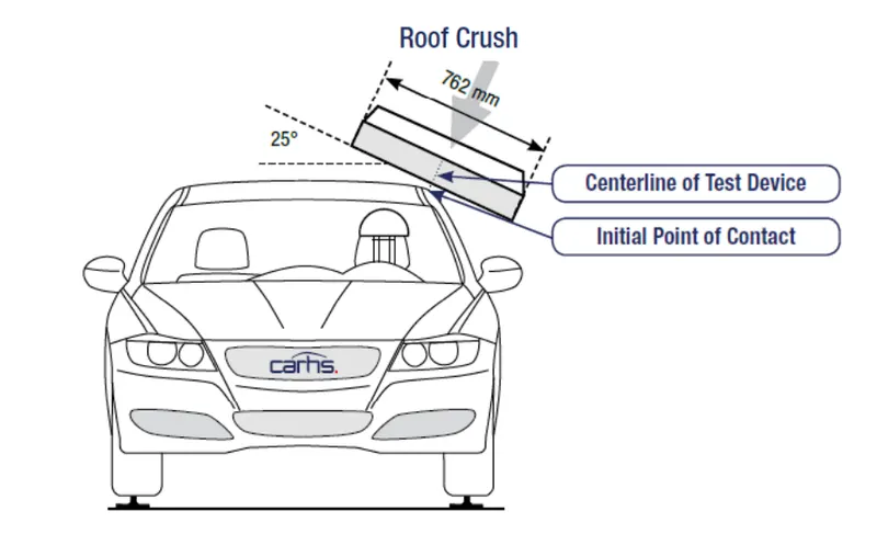
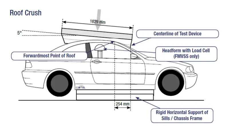
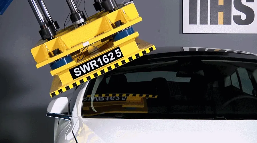
Here from the above gif, we can see that a tesla model vehicle is undergoing the roof crash test analysis by applying a certain load on the roof of the vehicle. which will be a similar thing that we will be doing in this project.
2) Procedure:
Import of the Model:
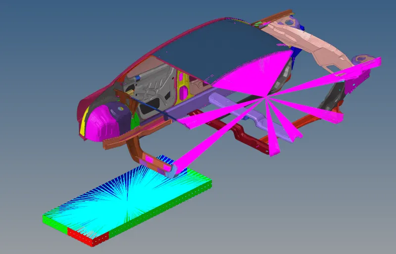
After successfully importing the model we follow the Transform rules where we set up the model with the given conditions to perform the roof crash test.
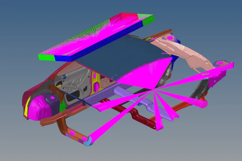
Here from the above figure, we can see that the model has been set up by following all the transform conditions that were given to us which were.
• A 180° rotation about the global z-axis with the point opposite to C as a base point
• A 5° rotation about the axis through axis AB
• A 25° rotation about the axis through axis AC
• A translation to put point A at global ( -3500.00, 584.822, 1343.06)
Creating Interfaces:
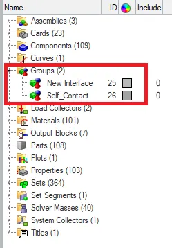
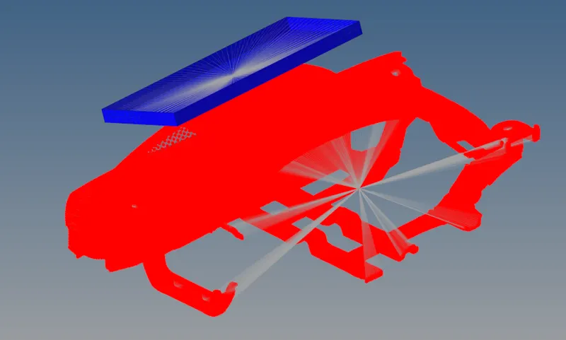
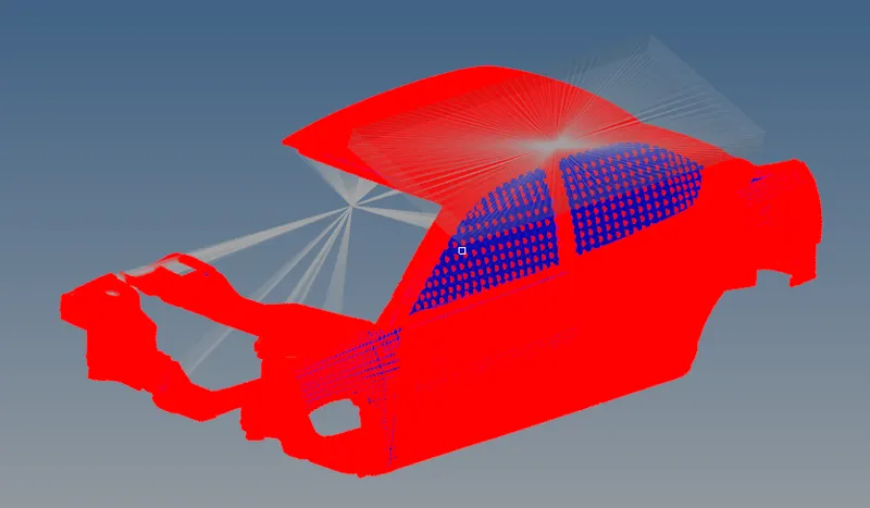
Here in this case we create two new interfaces with all the recommended parameters.
Review of the Interfaces:
For Contact Interface:
For Self-Contact Interface:
Giving Boundary conditions:
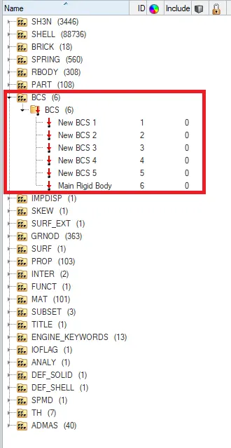
Here from the above case we create the boundary conditions and kept the suspension shock tower nodes locked in the Z-direction.
Imposed Displacement:
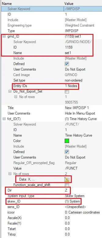
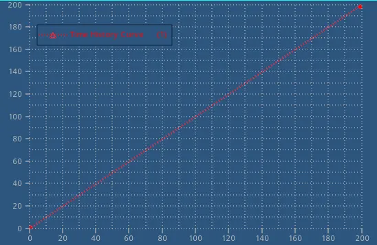
Here from the above-imposed displacement card image, we have given the velocity of the impactor starting from the initial point at t=0 and the displacement of the impactor is given as 200mm @ 200ms by creating a time history curve. This can be seen in the above plotting.
Control Cards:
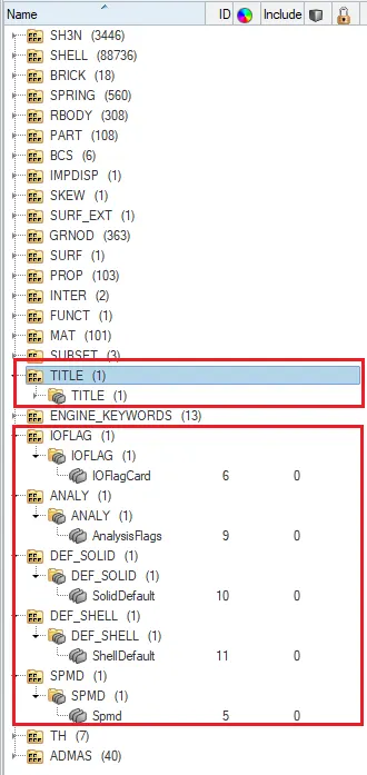
All the control cards are present in the solver. So then we can proceed to the further steps.
Penetrations Check:
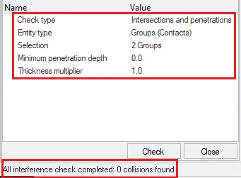
As we have checked for the penetrations check there were 0 collisions found to be there and we can proceed with the model checker.
Model Checker:
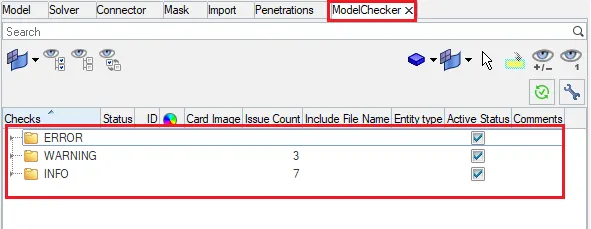
As we have undergone with the model checker there were no errors so far and few warnings which were to be ignored and set to proceed for the simulation.
Result:
Output Animation Files for Different Result Types:
For Displacement:
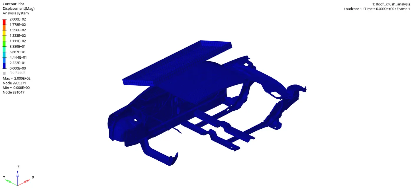
Here from the above output displacement animation file, the maximum displacement applied for this case was 200 mm.
For Von misses Stress:
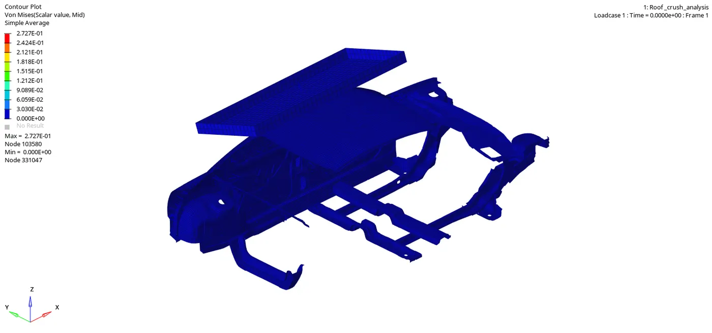
Here from the above output, Von mises stress animation file, The maximum Stress for this case was 0.272 Gpa.
For Plastic Strain:
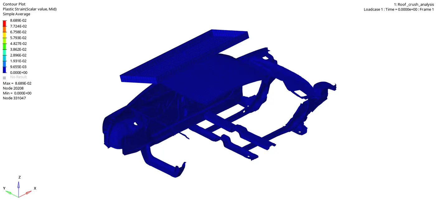
Here from the above output plastic strain animation file, The maximum Plastic strain was 0.086 mm.
For Nodal Mass:
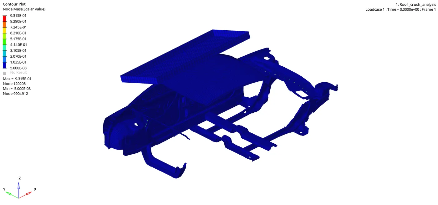
Here from the above output nodal mass animation file, The maximum nodal mass is 0.9315 kg.
Energy vs Time:
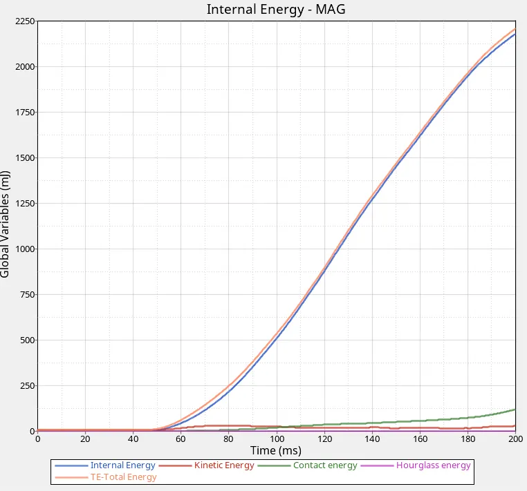
- Here from the above energy vs Time Curves, energies of Internal, kinetic, contact, hourglass, and total energy curves are plotted.
- Internal energy is inversely proportional to kinetic energy.
- At a point of 50 ms, the kinetic energy decreases and the internal energy increases as there is contact between the roof and the rigid body.
- Hourglass energy is zero as we have applied the recommended parameters.
- The total energy is the addition of all the energies whereas TE= I.E+K.E+C.E+H.E.
Force vs Displacement:
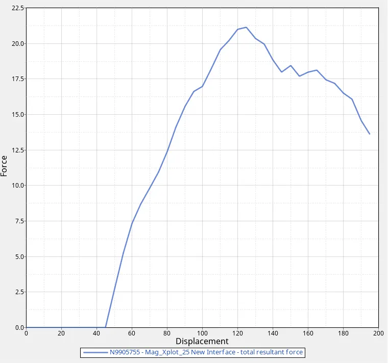
- Here from the Force vs Displacement curves,
- The rigid plate was in contact with the roof at a point of 45 ms.
- Force acting on the roof started from point 45 ms.
- The maximum force applied on the roof of the car was 21 N at a point of 125 ms.
- The total displacement for this case was 140 m.
Conclusion:
Roof crash Test analysis of the BIW model is carried out by using the crash Hyper crash & Radioss.
FMVSS Standards:
Here the total mass of the vehicle is of 170 kg
Converting Kg to KN i.e 170 x 9.81 = 1667.7 KN
Resistive force = 3 x 1667.7 = 5003.1 N
Therefore the resistive force = 5.1 KN
The maximum Peak velocity registered in the Force vs Displacement plotting is 21 KN which is very high compared to the resistive force.
By this, we conclude that the given BIW vehicle model has failed in the roof crash test analysis as the half-vehicle Model given. If there would have been the full model given to us there would be an increment in the Resistive force which would have matched the FMVSS standards criteria and would have passed the roof crash test analysis.