Project 1 Mechanical design of battery pack
AIM:
- Prepare a detailed battery pack drawing along with its enclosure. State your assumptions
Hint - Battery pack capacity: 18 kWh, Cell: ANR26650M1-B
OBJECTIVES:
- Explain the requirements as in detail
- Ensue with the referred formulae and calculations
- Make sure as all the provided information were correct
1. PREPARE A DETAILED BATTERY PACK DRAWING ALONG WITH ITS ENCLOSURE. STATE YOUR ASSUMPTIONS
Following will gives the detailed information about the specified battery's working and operations with example of real-time applications,
LITHIUM-ION BATTERY:
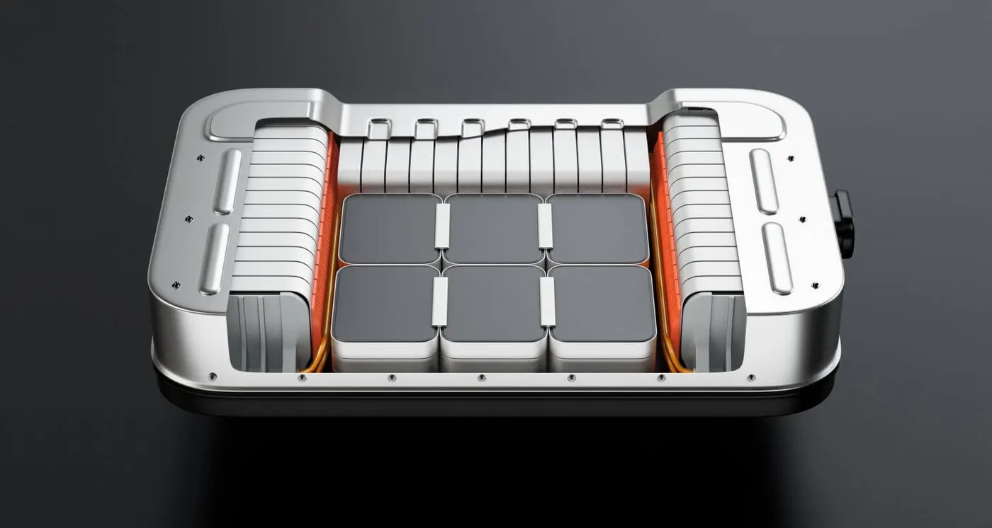
- First proposed in the 1970s and produced commercially by Sony in 1991, lithium batteries are now used in mobile phones, airplanes and cars
- A battery is a device consisting of one or more electrochemical cells with external connections for powering electrical devices
- When a battery is supplying electric power, its positive terminal is the cathode and its negative terminal is the anode
- The terminal marked negative is the source of electrons that will flow through an external electric circuit to the positive terminal
- When a battery is connected to an external electric load, a redox (reduction-oxidation) reaction converts high-energy reactants to lower-energy products, and the free-energy difference is delivered to the external circuit as electrical energy
- Historically the term "battery" specifically referred to a device composed of multiple cells; however, the usage has evolved to include devices composed of a single cell
lithium batteries made of?
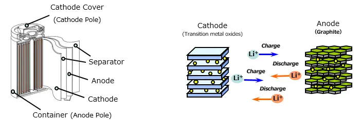
- A lithium battery is formed of four key components. It has the cathode, which determines the capacity and voltage of the battery and is the source of the Lithium-ions
- The anode enables the electric current to flow through an external circuit and when the battery is charged, Lithium-ions are stored in the anode
- The electrolyte is formed of salts, solvents and additives, and serves as the conduit of Lithium-ions between the cathode and anode. Finally there is the separator, the physical barrier that keeps the cathode and anode apart
How does a lithium-ion battery works?
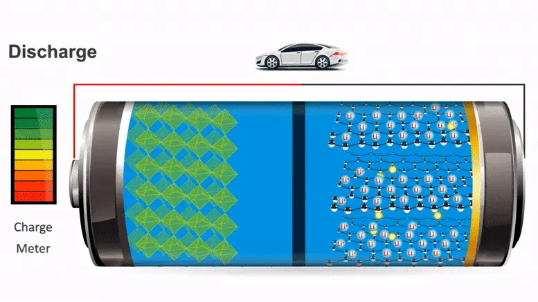
- Most Li-ion batteries share a similar design consisting of a metal oxide positive electrode (cathode) coated onto an aluminum current collector, a negative electrode (anode) made from carbon/graphite coated on a copper current collector, a separator and electrolyte made of lithium salt in an organic solvent
- While the battery is discharging and providing an electric current, the electrolyte carries positively charged Lithium-ions from the anode to the cathode and vice versa through the separator
- The movement of the Lithium-ions creates free electrons in the anode which creates a charge at the positive current collector
- The electrical current then flows from the current collector through a device being powered (cell phone, computer, etc.) to the negative current collector. The separator blocks the flow of electrons inside the battery
- During charging , an external electrical power source (the charging circuit) applies an over-voltage (a higher voltage than the battery produces, of the same polarity), forcing a charging current to flow within the battery from the positive to the negative electrode, for example in the reverse direction of a discharge current under normal conditions
- The Lithium-ions then migrate from the positive to the negative electrode, where they become embedded in the porous electrode material in a process known as intercalation
Primary and secondary cells
- Primary batteries, or cells, are not rechargeable, and must be discarded once their charge is exhausted. By contrast, secondary types can be recharged using an external electric charger
- Today, most attention is given to secondary types, particularly Li-ion batteries, because of their widespread application in cell phones and electric vehicles
- However, primaries still play an important role, especially when charging is impractical or impossible, such as in military combat, rescue missions and forest-fire services
- Regulated under IEC 60086, primary batteries also service pacemakers in heart patients, tire pressure gauges in vehicles, smart meters, intelligent drill bits in mining, animal-tracking, remote light beacons, as well as wristwatches, remote controls, electric keys and children's toys
Lithium-ion battery applications
Lithium-ion batteries are popular because of their high energy density and other properties – and as the technology improves and prices reduce, they are proliferating in many applications. Here are some examples for Li-ion battery applications:
- Portable power packs: Li-ion batteries are lightweight and more compact than other battery types, which makes them convenient to carry around within cell phones, laptops and other portable personal electronic devices
- Uninterruptible Power Supplies (UPSs): Li-ion batteries provide emergency back-up power during power loss or fluctuation events. Office equipment like computers, as well as IT servers and complete data centers, must be protected from power interruptions to prevent data loss. Back-up power is also needed in the medical and health care industries to guarantee consistent power supply to life-saving medical equipment
- Electric vehicles: The automotive industry is creating a demand for Li-ion battery packs to provide power sources for electric, hybrid or plug-in hybrid electric vehicles. As Li-ion batteries can store large amounts of energy and can be recharged many times, they offer good charging capacity and long lifespans
- Marine vehicles: Li-ion batteries are emerging as an alternative to gasoline and lead-acid batteries in powering work or tug boats and leisure craft like speed boats and yachts. Li-ion batteries provide quiet and efficient power sources and can also be used to provide electricity to appliances inside the boat while it is in dock
- Personal mobility: Lithium-ion batteries are used in wheelchairs, bikes, scooters and other mobility aids for individuals with disability or mobility restrictions. Unlike cadmium and lead batteries, lithium-ion batteries contain no chemicals that may further harm a person's health
- Renewable energy storage: Li-ion batteries are also used for storing energy from solar panels and wind turbines as they can be charged quickly. They are lighter, more compact and can hold higher amounts of energy than lead-acid batteries. Within battery energy storage systems, they fulfil a valuable role in balancing supply and demand, and in grid stabilization
Types of lithium-ion batteries
There are many types of lithium-ion batteries, which are
- Lithium Cobalt Oxide (LCO) - `LiCoO_2`
- Lithium Manganese Oxide (LMO) - `LiMn_2O_4`
- Lithium Nickel Manganese Cobalt Oxide (LNMC) - `LiNiMnCoO_2`
- Lithium Nickel Cobalt Aluminum Oxide (LNCA) - `LiNiCoAlO_2`
- Lithium Iron Phosphate (LFP) - `LiFePO_4`
- Lithium Titanate Oxide (LTO) - `LiTiO_3`
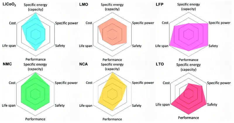
From above mentioned battery types, three types of lithium batteries are particularly suitable for an EV battery, namely `LiMn_2O_4`, `LiFePO_4` and `LiNiMnCoO_2`
Here we going to discuss about the required battery of 'Lithium Iron Phosphate (LFP)'
LITHIUM IRON PHOSPHATE (LFP)
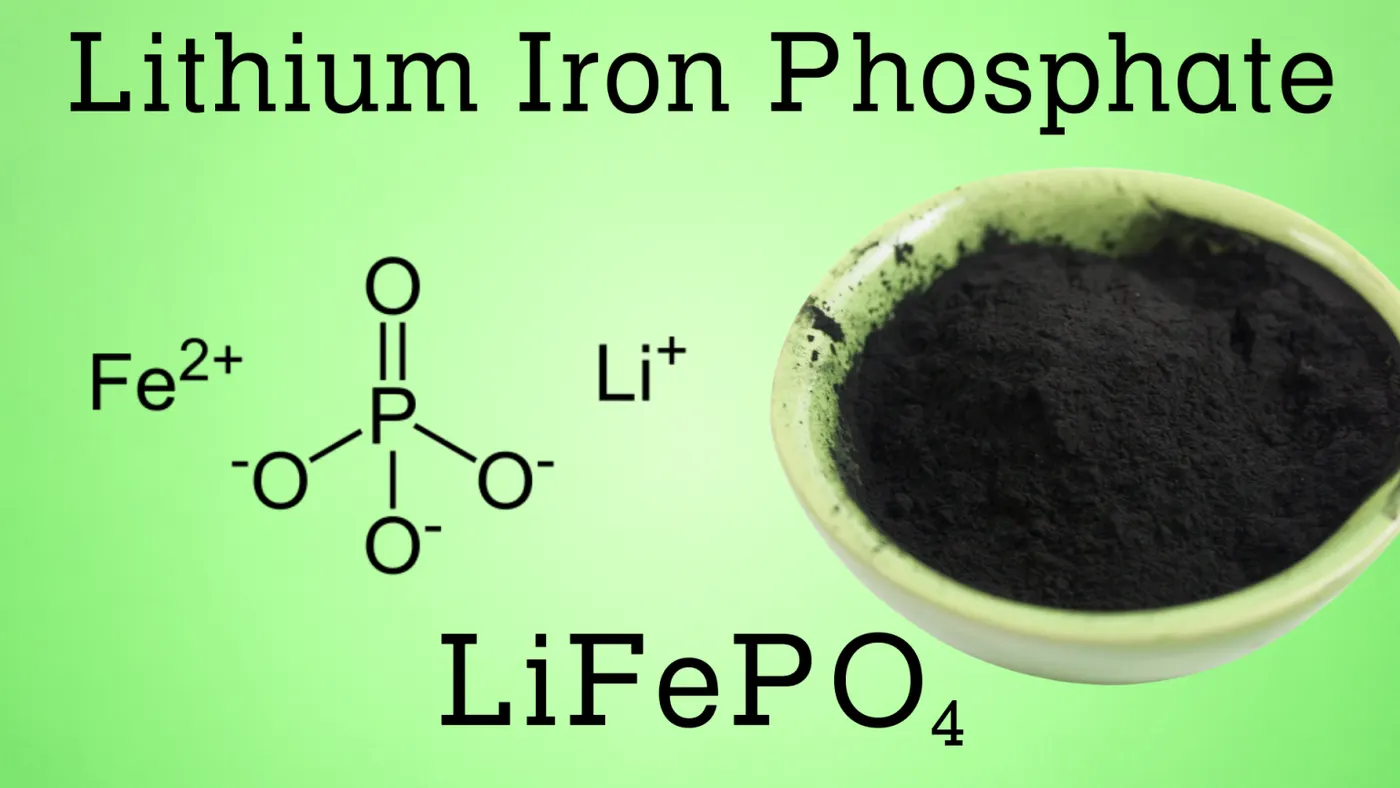
- In 1996, the University of Texas (and other contributors) discovered phosphate as cathode material for rechargeable lithium batteries
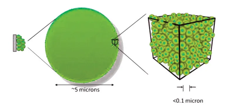
- Li-phosphate offers good electrochemical performance with low resistance. This is made possible with nano-scale phosphate cathode material
- The key benefits are high current rating and long cycle life, besides good thermal stability, enhanced safety and tolerance if abused
- Li-phosphate is more tolerant to full charge conditions and is less stressed than other lithium-ion systems if kept at high voltage for a prolonged time
- As a trade-off, its lower nominal voltage of 3.2V/cell reduces the specific energy below that of cobalt-based lithium-ion
- With most batteries, cold temperature reduces performance and elevated storage temperature shortens the service life, and Li-phosphate is no exception
- Li-phosphate has a higher self-discharge than other Li-ion batteries, which can cause balancing issues with aging
- Cleanliness in manufacturing is of importance for longevity. There is no tolerance for moisture, lest the battery will only deliver 50 cycles. Figure 9 summarizes the attributes of Li-phosphate
- Li-phosphate is often used to replace the lead acid starter battery. Four cells in series produce 12.80V, a similar voltage to six 2V lead acid cells in series
- Vehicles charge lead acid to 14.40V (2.40V/cell) and maintain a topping charge. With four Li-phosphate cells in series, each cell tops at 3.60V, which is the correct full-charge voltage
- At this point, the charge should be disconnected but the topping charge continues while driving. Li-phosphate is tolerant to some overcharge; however, keeping the voltage at 14.40V for a prolonged time, as most vehicles do on a long drive, could stress Li-phosphate. Cold temperature operation starting could also be an issue with Li-phosphate as a starter battery
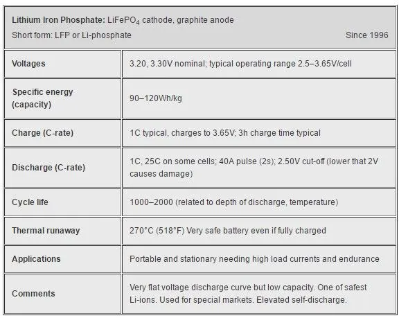
Lithium iron phosphate batteries have several distinctive features, including:
- Better power density
- Low discharge rate
- Flat discharge curve
- Less heating
- Higher number of charge cycles
- Increased safety
Energy Density
- LFP batteries have one of the highest specific power ratings amongst other lithium-ion types. In other words, high specific power means that LFP batteries can deliver high amounts of current and power without overheating
- On the other hand, it is important to keep in mind that LFP batteries have one of the lowest specific energy ratings. Low specific energy means that LFP batteries have less energy storage capacity per weight than other lithium-ion options
- This is typically not a big deal because increasing the battery bank's capacity can be done by connecting multiple batteries in parallel
- This may not be ideal for an application where extreme energy density in a very light space is required, like battery electric vehicles
Battery Life Cycles
- Lithium iron phosphate batteries have a life span that starts at about 2,000 full discharge cycles and increases depending on the depth of discharge
- Cells and the internal battery management system (BMS) used at Dragonfly Energy have been tested to over 5,000 full discharge cycles while retaining 80% of the original battery's capacity
- LFP is second only to lithium titanate in lifespan. However, LTO batteries have traditionally been the most expensive lithium-ion battery option, making them cost-prohibitive for most applications
Discharge Rate
- Discharge rate is measured in a multiple of the battery's capacity, meaning a 1C discharge rate for a 100Ah battery is 100A continuous
- Commercially available LFP batteries traditionally have a 1C continuous discharge rating but can exceed this for short periods depending on the battery management system
- LFP cells themselves typically can provide a 25C discharge for short periods safely. The ability to exceed 1C allows you to use LFP batteries in high-power applications that may have startup spikes in the current draw
Operating Temperatures
- LFP batteries don't enter thermal runaway conditions until around 270 degrees Celsius. Compared to the other common lithium-ion battery options, LFP batteries have the second-highest operating temperature limit
- Exceeding the temperature limit on a lithium-ion battery causes damage and can lead to thermal runaway, possibly resulting in a fire. The high operating limit of LFP significantly decreases the chance of a thermal runaway event
- Combined with a high-quality BMS to shut down the cells well before these conditions (at around 57 degrees Celsius), LFP offers significant safety advantages
Safety Advantages
- LFP batteries are one of the stable chemistries of all of the lithium-ion options. This stability makes them one of the safest options for both consumer-facing and industrial applications
- The only other comparably safe option is lithium titanate, which again is typically cost-prohibitive and does not operate at the correct voltage in most situations for a 12V replacement
SERIES AND PARALLEL CONNECTION:
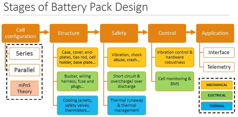
- While researching lithium batteries, you've probably seen the terms series and parallel mentioned. We are frequently asked the questions like, "what's the difference between series and parallel", "can RELiON batteries be connected in series"
- It can be confusing if you're new to lithium batteries or batteries in general, but hopefully, we can help simplify it
- Let's start at the beginning - your battery bank. The battery bank is the result of connecting two or more batteries together for a single application (i.e. a sailboat)
- What does joining more than one battery together accomplish? By connecting the batteries, you either increase the voltage or amp-hour capacity and sometimes both, ultimately allowing for more power and / or energy
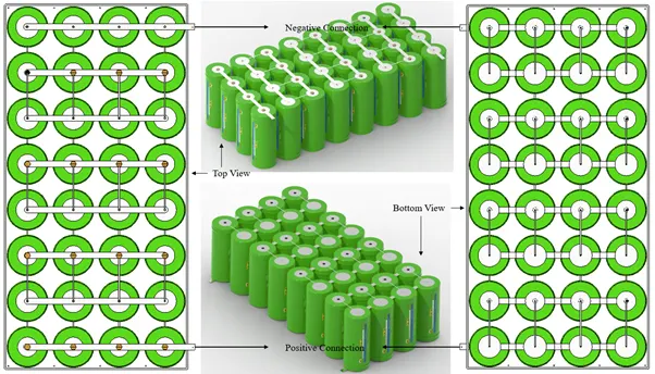
- The first thing you need to know is there are two primary ways to successfully connect two or more batteries: The first is called a series connection and the second is called a parallel connection
Series Connections
- Series connections involve connecting 2 or more batteries together to increase the voltage of the battery system but keeps the same amp-hour rating
- Keep in mind in series connections each battery needs to have the same voltage and capacity rating, or we can end up damaging the battery
- To connect batteries in series, you connect the positive terminal of one battery to the negative of another until the desired voltage is achieved
- When charging batteries in series, you need to utilize a charger that matches the system voltage. Recommended suggestion was to charge each battery individually, with a multi-bank charger, to avoid an imbalance between batteries
- The overall emf of the battery is the algebraic sum of all individual cells connected in series
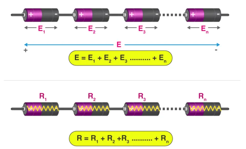
- If E is the overall emf of the battery combined by n number of cells, then
`E=E_1+E_2+E_3+E_4+.....+E_n`
- Similarly, if r1, r2, r3 are the internal resistances of individual cells, then the internal resistance of the battery will be equal to the sum of the internal resistance of the individual cells
`r=r_1+r_2+r_3+.....+r_n`
- In the image above, there are two 12V batteries connected in series which turns this battery bank into a 24V system and we can also see that the bank still has a total capacity rating of 100 Ah
Advantages
- Wiring batteries in series provides a higher system voltage resulting in a lower system current
- Low current indicates that you can use thinner wiring and suffer less voltage drop in the system
Disadvantages
- In a series-connected battery system, a converter is needed to achieve low voltages
Parallel Connections
- Parallel connections involve connecting 2 or more batteries together to increase the amp-hour capacity of the battery bank, but the voltage stays the same
- To connect batteries in parallel, the positive terminals are connected together via a cable and the negative terminals are connected together with another cable until you reach your desired capacity
- A parallel connection is not meant to allow your batteries to power anything above its standard voltage output, but rather increase the duration for which it could power equipment
- It's important to note that when charging batteries that are connected in parallel, the increased amp-hour capacity may require a longer charge time
- If the emf of each cell is identical, then the emf of the battery combined by n numbers of cells connected in parallel is equal to the emf of each cell. The resultant internal resistance of the combination is,
`1/r=(1/r_1+1/r_2+1/r_3+......1/r_n)^-1`
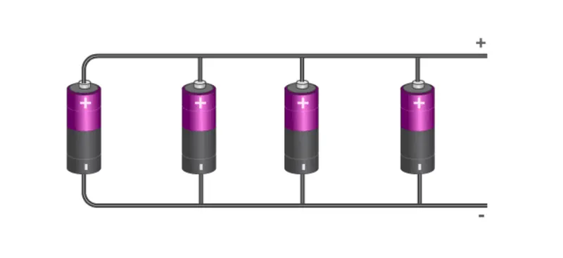
- The current delivered by the battery is the sum of currents delivered by individual cells
- In the example below, we have two 12V batteries, but you see the amp-hours increase to 200 Ah
Advantages
- One of the prominent advantages of batteries connected in parallel is that if one of the batteries in the system fails to operate, the remaining batteries can still provide power
Disadvantages
- Connecting batteries in parallel results in a higher current draw. This indicates thicker cables and more voltage drop
MECHANICAL MODELLING AND DESIGN OF BATTERY PACKS:
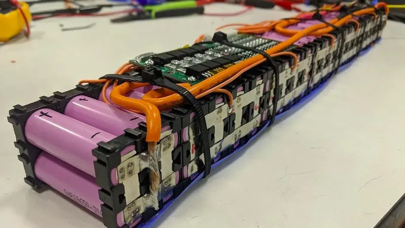
- By using CAD to accurately model the battery system in combination with the electrical modelling of the battery system
- And work with Catia v5 and Fusion 360 depending on the requirements of the project. Design is done concurrently between electrical design and mechanical design
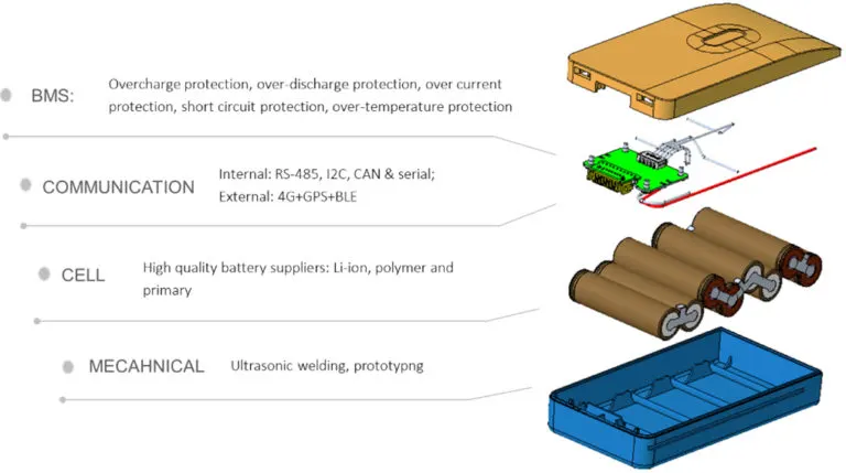
- There is also a focus on material selection to achieve the electrical performance specifications, especially in bolted mechanical joints and welded joints
- We have an extensive material and surface coating library of specifications for different levels of performance that cover most markets. On this front, work with specialist suppliers to achieve the quality and reliability expected
Mechanical Components of Battery Pack
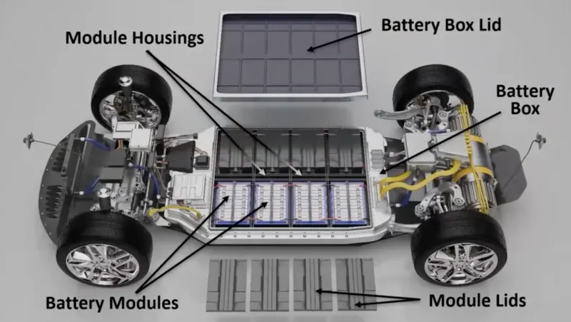
Following would helps to understand about the idea of EV battery pack construction and it's components,
Plastic Cell Separators / Spacers
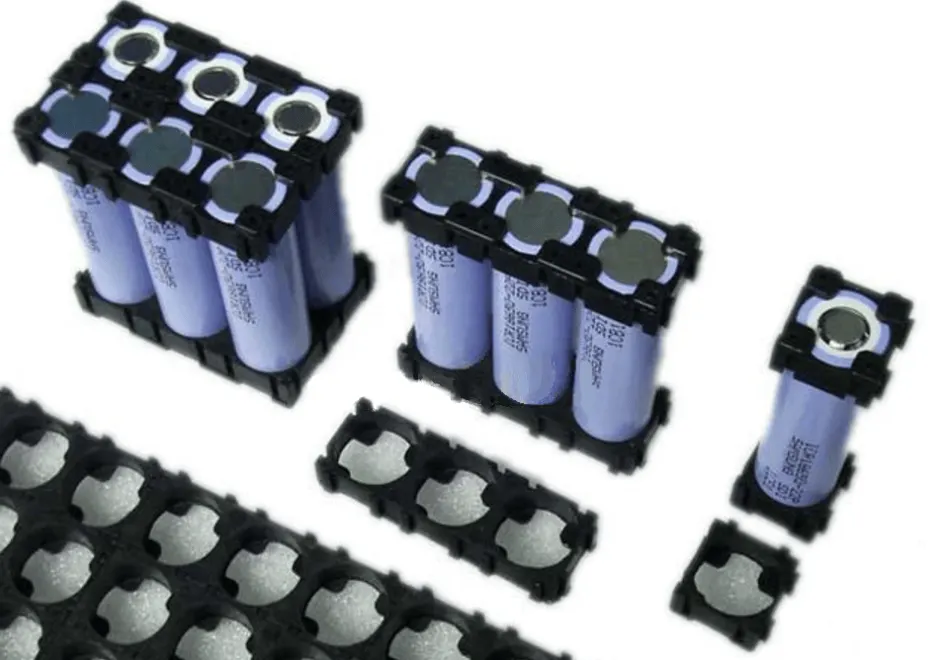
- For a very long time, there has existed a plastic end-cap design that helps the pack-builder to assemble a pack. The "slot" on top of the cells is an 8mm wide alley, which is often filled with a 7mm wide ribbon of pure nickel (nickel bus-ribbon that is o.15mm or 0.20mm thick are the most common)
- As I found out when I was researching the 18650-format cell construction article, that the sides and bottom of every 18650 cell is one continuous conductor (ie: the sides and bottom of the cell are negatively charged)
- This means that…these plastic end-caps are very important. Vibration over the years can break through the PVC insulation-sleeve that comes over the sides of the cells, and a break right there will allow a short-circuit near the positive end
- The area near the shoulder of the positive cathode of the cell is the "danger zone", and a compromise there is something that I call a "shoulder short" (the end with the white ring, in the pic below). It is very beneficial to add a self-adhesive fiber insulation washer to the positive end, and to use some type of plastic end-cap
- Once you decide on an available model of plastic end-cap, how do you attach each cell in series and parallel? The pic below is a common 2S / 4P bus-plate
- In that pic, the four vertical pathways on the nickel bus-plate carry the high series current. If these are 10A cells, then each one of the four vertical runs carry 10A each, for a total of 40A for the whole pack
- The two horizontal pathways carry the paralleling current, which only keeps the cells at an equal voltage as they charge and discharge. It will typically be less than 1A, even for very high-powered battery packs
- The only reason the series and parallel pathways are the same width and thickness on this common style of bus-plate, is that doing this makes it fast and easy to laser-cut the shape, and the nickel is stiff enough to add some structural rigidity to the resulting pack
- To be clear, if you are charging your pack with a 5A charger, that 5-Amps is charging "in series" too, so…the parallel connections will only carry a tiny amount of balancing current, under all charging and discharging conditions
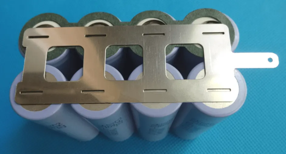
- In fact, nickel is not a great conductor. It is only used for two main reasons. I ‘would' state that it has very strong anti-corrosion characteristics, but nickel-plating over copper bus-plates [or aluminum] has the same corrosion protection, and that composition would conduct better and costs less (nickel is expensive, and getting pricier each year)
- The first reason is that pure nickel is stiff, and provides some structural strength, while copper or aluminum is malleable (soft and easily bendable)
- The second reason is that pure nickel [as a bus material] will spot-weld quite easily and very fast, which helps the assembly-line move along rapidly
- Although many packs are still spot-welded in China one cell at a time by a person, the trend is to have robots spot-weld a pack together very rapidly
- Notice the slot that is located over each cell in the pic above. Electrical current-flow will take the "path of least resistance", and that means that if you include a slot over the cell
- Then the majority of the spot-welding electrical pulse is forced to pass through the end of the cell, instead of just passing through the bus-plate (from one welding probe to the other), which is what would happen if the nickel ribbon did not have that slot

- This provides a more consistent result, when spot-welding cells to bus-plates. Personally, I am a fan of the "honeycomb" configuration, over the now common rectangular "rank and file" shape (shown above)
- Using a honeycomb layout is mathematically the most compact way to arrange cells. That being said, the common rank-and-file arrangement leaves "just enough" space between four adjacent cells to allow a thin bolt to pass through from one side plate to the other (as seen below), and a honeycomb does not
- The plastic end-cap cell holders are an important safety feature for a DIY pack. The common square layout usually positions the cells so that they are almost touching each other
- That means there will be almost no air-circulation, and that leads to the cells in the center of the pack to gradually run warmer by the end of a ride
- If you have a large enough pack, and the cells can provide lots of current, then…a low-current ride will not even get them warm
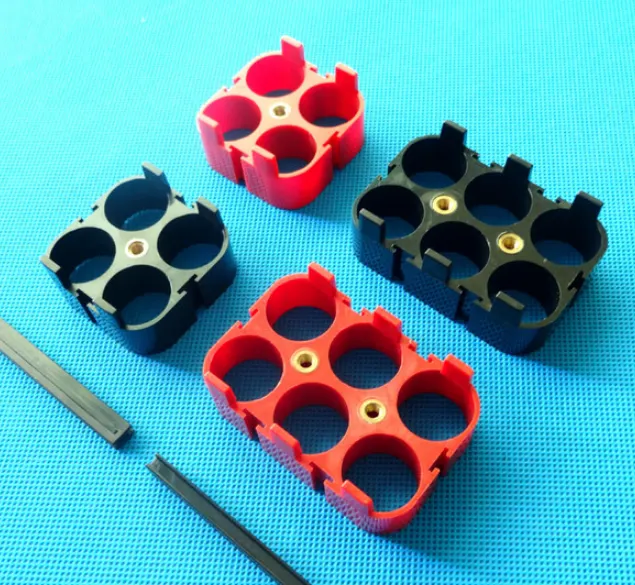
- At the other end of the scale, a small pack of low-current cells that are being hammered on a ride will definitely get hot. The hottest spot will always be the positive cathode tips on the cells in the center of the pack
- For roughly the same volume of battery pack, the honeycomb layout provides more air-flow between each cell. Whether you are trusting in passive heat-shedding, or a pro-active fan-cooling system if you have a more consistent air-flow envelope around each cell? It will help each cell to shed any of the heat that develops
Battery Blocs
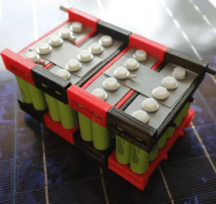
- The "Battery Bloc" system has a wide variety of sizes for each 18650-cell paralleled module. One interesting feature is that they use a long plastic bolt to connect both ends
- It is interesting because the entire sides of an 18650 cell are negatively charged. Although swapping-in a common steel bolt would not touch the sides of the can, the amount of compression needed is low enough that a plastic bolt is acceptable, and the added safety is always a good design goal (if your battery is involved in a crash)
- The most noteworthy feature of this kit is that…they use a small-but-strong neodymium "button" magnet as the connector to each cell-end
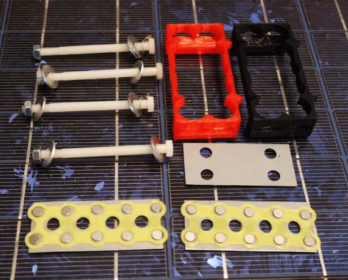
- These magnets are mostly composed of steel, so…they are not good for high amps. This is not any issue for a very large "low-amps-per-cell" Power Walls
- However, if you want to use these for the battery of a a longtail cargobike, upgrading the amp-capacity of the connections may involve adding a copper foil ribbon in-between the magnet and cell-tips (for initial experiments, you might consider using 0.25mm thick, 10-mil / 30-ga copper sheet). Battery Bloc kits are available in a variety of configurations (4P, 6P, 8P, etc)
In application view,

- In the above picture, you can see that when using a honeycomb pattern, the side angle of the stacked cells is about 30-degrees away from the 90-degree corners in a common rectangular pack
- This makes it a natural fit into the lower part of the frame triangle space. Mounting the weight of a pack low and in the center of the frame is the best place to put them, so the bike will handle well
Triangle packs, and odd shapes -
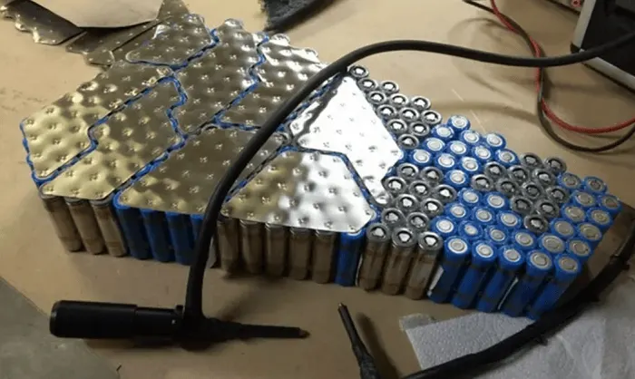
- The easiest pack to design is a rectangle (as seen above). However, like the pic below, it's sometimes useful to make your pack a triangle, or some other odd shape
- In the picture above, the builder is trying out a dry-fit to see how the 100 cells shown would work, and also how to arrange the 5P paralleled groups which are now in odd-shaped clusters (instead of being in-line).
Analytical Models for Battery Pack
- As continuously developing basic cell models for simulation of battery packs. These tools are very powerful to predict the behaviour of the battery and correct dimensioning of the system
- The basic unit of a battery is the lithium-ion cell, which is combined in a pack to create a battery. Although the lithium-ion cell is the main ingredient that controls the battery pack performance, the arrangement in which cells are combined largely determines the behaviour of the pack
- Many companies can arrange Lithium-ion cells in a cradle and create a battery pack, but few can develop a pack from analytical models
- There is great potential in these tools and pushing to improve the mathematical models and testing required to achieve an efficient design in terms of cost, volume and durability
- Since both aspects are interrelated, getting accurate data from physical tests to adjust the model is crucial to understand and simulate the battery pack behaviour
Thermal Management of Lithium-ion Cells
- The thermal management of the lithium-ion cells for a custom battery pack is an important aspect of the system
- Lithium-ion cells are the most efficient cells currently used for electric vehicles. However, they are sensitive to degradation with time and operating temperature
- The degradation as a function of time is also linked to temperature, thus it is important to be able to have control over the thermal behaviour of the battery pack
- There are different approaches for battery thermal simulations. Mainly analytical models using MATLAB / Simulink and CFD (Computational Fluid Dynamics) tools to perform thermal simulations on battery packs from CAD and analytical models
- The cooling system of a battery pack is designed based on the usage of the pack, mostly linked to ambient temperature range and charge/discharge rate of the Lithium-ion cells
- Liquid cooling systems are used for high discharge rates, such as the battery packs used in electric vehicles and more particularly in motorsport
- These systems are efficient in dissipating heat from the cells on to external air via a heat exchanger. However, that comes at a cost penalty
- Other battery packs are cooled by convection using forced air flowing around the cells. These systems are simpler, but air is not as efficient as liquid cooling
- CFD simulation can predict temperatures on the cells and cooling system, by using a finite element approach to solve the problem. These sorts of studies require huge computation power
- Accuracy is important because a small temperature difference on cells (e.g. 5°C difference) can cause noticeable capacity and performance differences
Cooling System for Lithium-ion Cell Battery Packs
- The cooling system is vital for most battery systems. Especially for high power battery system for motorsport, automotive and other short cycle devices
- The mechanical engineering expertise is very strong with on this field to design the entire cooling system inside and outside the battery pack
- Inside the battery pack, the system is in close contact with the cells. In liquid cooling systems, the fluid is transferred outside the pack to a heat exchanged which is usually then cooled by air
- This is very effective thermally but has impact on the aerodynamics and weight. However, some battery systems might only be cooled using liquid systems due to the high power of the unit
- Formula E Gen-1 propulsion system showing the battery pack radiators that cool the lithium-ion cells
DATASHEET:
Required Datasheet: https://store-cvt2jlgam8.mybigcommerce.com/content/LithiumWerks%20ANR26650M1-B%20Power%20Cell%20%28030921%29%20Data%20Sheet.pdf
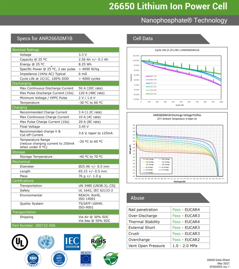
ANR26650M1-B Cell
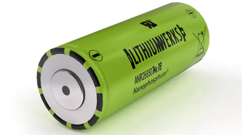
- This cell deliver very high power due to their use of applications. Based on lithium iron phosphate chemistry (LiFePO4), the cells are inherently safe over a wide range of temperatures and conditions
- Whether the application requires outstanding cycle life or stable float reliability, the 26650 cells are suitable for a wide variety of power, pulse or stand-by applications
- This battery technology offers thermal-stable chemistry, faster charging, consistent output, low capacity loss over time and superior total cost of ownership (TCO). It provides the foundation for safe systems while meeting the most demanding customer requirements
- Multiple layers of protection are employed at the chemistry, cell and system level to achieve an energy storage solution with superior safety and abuse tolerance compared to metal oxide lithium-ion chemistries
Applications
- Energy storage
- Frequency regulation
- Uninterruptible Power Supplies
- Communication technologies
- Aviation / Aerospace
- Electrified mobility devices
- Industrial equipment
- Medical devices
- Consumer Products
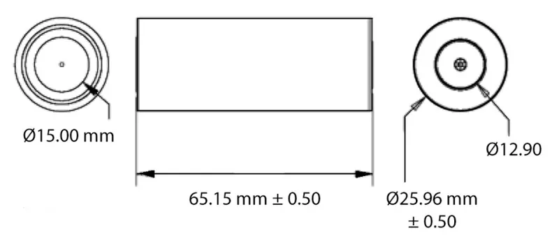
Dimensions
CALCULATIONS:
Now let's calculate that, how many of cells were needed as series and parallel arrangement to satisfied the 18 kWh battery capacity,
Solutions
1. Calculate Cell Energy
- For single cell,
Nominal Voltage,V = 3.3 V
Nominal Current,I = 2.5 A
Nominal Capacity = 2.5 Ah
Nominal Cell Energy, Ec = Voltage * capacity = 3.3 * 2.5 = 8.25 Wh
2. Series and Parallel Battery Pack Assembly
- By assumption,
No.of cells in series = 44
No.of cells in parallel = 50
Total no.of batteries = Series * Parallel = 44*50 = 2200 cells
So the configuration of the pack is 44S 50P
4. Energy Calculation of the Battery Pack
For overall energy calculation of battery pack, Ebp = Total no.of batteries * cell energy = 2200*8.25 = 18150 Wh = 18.15 kWh
- The above result were almost attained the specified energy capacity (18kWh) of the battery pack
5. Calculate the Voltage and Current of the Battery Pack
Series configuration:
Voltage of battery pack,`V_s`=No.of cells in series*Nominal voltage of one cell
`V_s=44*3.3=145.2V`
Thus the voltage of the battery pack is 145V
Parallel configuration:
Current of battery pack,`I_p`=No.of cells in parallel*Nominal current of one cell
`I_p=50*2.5=125 A`
Thus the current of the battery pack is 125A
Capacity of the battery pack (energy stored) = 125Ah = 18.15kWh
6. Calculate the Battery Pack Dimensions (Mechanical Design)
- For single cell,
Diameter, dc = 25.96 mm = 0.02596 m
Radius, rc = 12.98 mm = 0.01298 m
Height, hc = 65.15 mm = 0.06515 m
Volume of the single cell (cylindrical), Vc = `pir^2h` = `pi*0.01298^2*0.06515` = `3.4483 e^-5` = 0.000034483 `m^3`
For the entire battery pack (2200 cells),
Volume of the battery pack = 2200 * `0.000034483 = 0.0758626 m^3`
Note: The dimensions of the battery pack has calculated on for the cells, the calculation has not included with the additional components (BMS and communication)
7. Calculate the Battery Pack Mass
For single cell, mc = 76 g
Mass of multi-cell in battery pack = 2200 * 76 = 167200 grams = 167.2 kg
Note: The mass of the battery pack has calculated were excluded the vehicle's additional components (wires, electronic components, soldering, case, etc.)
8. Calculate the Volumetric Energy Density of the Battery Pack
For battery pack, `u_V` = Battery pack energy/Volume of battery pack = `18.15/0.0758626` = 239.24 `(kWh)/(m^3)`
9. Calculate the Gravimetric Energy Density of the Battery Pack
For battery pack, `U_G` = Battery pack energy/Mass of battery pack = `18.15/167.2` = 0.108 `(kWh)/(kg)`
10. Energy Consumption of Battery Pack for Certain Distance
Let assume the vehicle has completely charged (100% SoC) and now it's travelled 75 kms,
Now estimate the total battery pack energy usage,
= Overall energy of battery pack (Wh) / vehicle travelled (kms)
= `18150/75=242(Wh)/(km)`
So the vehicle has consumed the energy of 242 Wh for 75 kms travel
Battery pack architectures
- All high voltage battery packs are made up from battery cells arranged in strings and modules. A battery cell can be regarded as the smallest division of the voltage
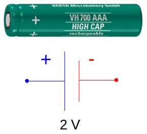
- Individual battery cells may be grouped in parallel and / or series as modules. Further, battery modules can be connected in parallel and / or series to create a battery pack. Depending on the battery parameters, there may be several levels of modularity
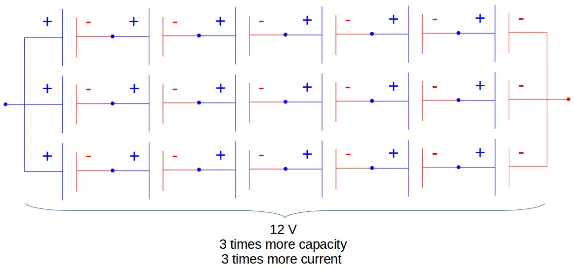
- The total battery pack voltage is determined by the number of cells in series. For example, the total (string) voltage of 6 cells connected in series will be the sum of their individual voltage

- In order to increase the current capability the battery capacity, more strings have to be connected in parallel. For example, 3 strings connected in parallel will triple the capacity and current capability of the battery pack
For some reference,
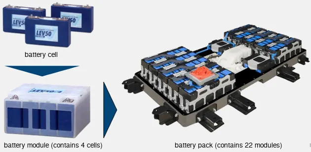
- The high voltage battery pack of Mitsubishi i-MiEV consists of 22 modules made up from 88 cells connected in series. Each module contains 4 prismatic cells. The voltage of each cell is 3.7 V and the total voltage of the battery pack 330 V
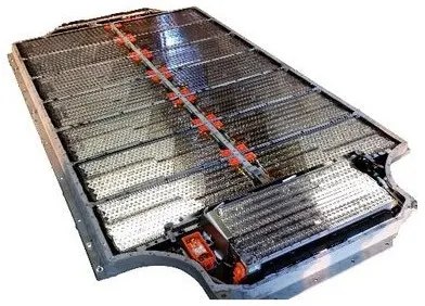
- Another example is the high voltage battery pack of Tesla Model S, which has:
1. 74 cells in a parallel group
2. 6 groups in series for a module
3. 16 modules in series
4. 7104 cells in total
REFERENCES:
- Battery Pack Manufacturing - https://www.sciencedirect.com/science/article/pii/S2666330920300157
- Calculation of EV battery pack design - https://x-engineer.org/ev-design-battery-calculation/
CONCLUSION:
- Based on the reference and the calculated data, we can choose the suitable battery cells for our electric vehicle battery pack as per the need