Simulink: Control Logic in Washing Machine & Gear Shift by using Stateflow Concept
AIM:
1. To implement control logic of a “washing machine” using Stateflow as per given sequence:
- If the power supply is available, the system gets activated
- If the Water supply is not available, stop the process & indicate through LED
- Soaking time should be 200s followed by Washing time of 100s
- Then rinsing happens for next 20s & dryer runs for 50s
After all the processes have completed turn on the finished LED
2. To make a Simulink chart for the “Gear shift” logic as per below conditions:
| Speed Range(kmph) | Gear |
| 0 - 15 | 1 |
| 16 - 25 | 2 |
| 26 - 40 | 3 |
| 41 - 60 | 4 |
| Above 61 | 5 |
Give speed input while the simulation is running & display the gear number
OBJECTIVE:
- Design the both models as per the requirements by the given data
- Ensure all the conditions applied in the stateflow are correct
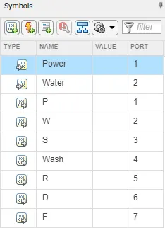
- Check the symbols pane once in both model's stateflow
- Make sure with inputs, stop time, lamp and scope connections
- Analyze the graphical representation at last
1. CONTROL LOGIC OF A WASHING MACHINE USING STATEFLOW
Given Data:
Soaking time: 200s
Washing time: 100s
Rinsing time: next 20s
Dryer time: 50s
MODEL:
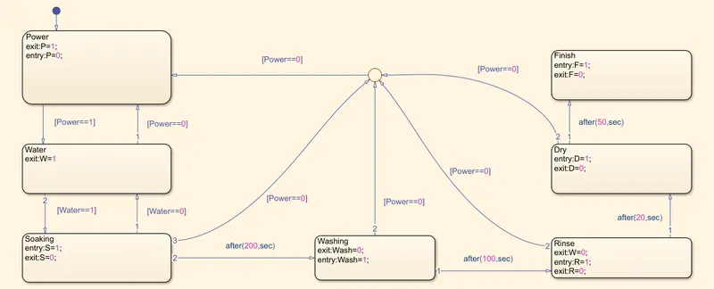
Fig 1. Washing Machine Stateflow
2. Washine Machine
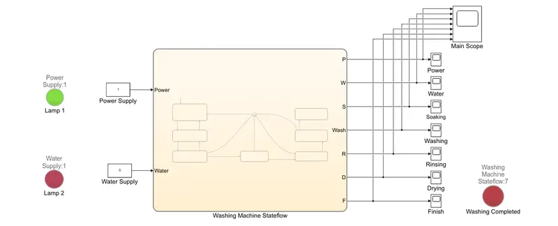
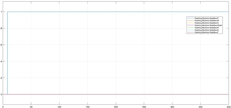
Case 1: [1 0] - If the power supply is available, the system gets activated, If the Water supply is not available, stop the process & indicate through LED
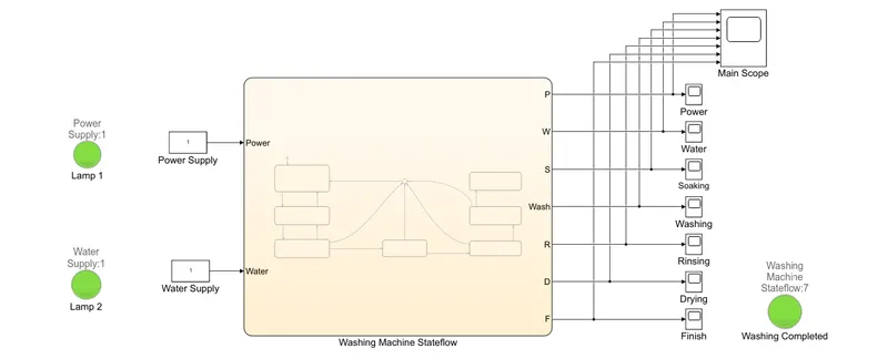
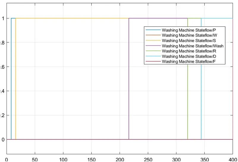
Case 2: [1 1] - After all the processes have completed turn on the finished LED
EXPLANATION:
- Here, we going to design the model of washing machine to run in the certain conditions as given
- So first we have to design a stateflow of the washing machine with the 7 processes which are power, water supply, soaking, washing, rinsing, drying and finish
- Use the chart block to construct the stateflow. On above Fig 1 has the snapshot of this stateflow, it's fully constructed by the 0 and 1 values
- Use the state option to construct the each processes of the washing machine, then connects all the blocks through the transition line
- Then connects all the electrical functioning process to the Power by the transition line through the junction
- After the design of each blocks in the stateflow, apply the given conditions as to run the each process as in the set amount of time
- Now exit from the stateflow and give two inputs (power and water supply) by using the constant block and connect those blocks with the lamps as seperately for the indication
- Then connects all the output of the 7 processes from the stateflow to the scope as seperately and again connect all the outputs in the 'single scope' for analyze the overall process
- And add one more lamp to connect with the scope of output - F (finish) to check the final process completion
- Set all the lamp conditions as per the following,
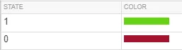
- Finally, set the stop time (~400), before the program run, check the port numbers in the symbols pane on the stateflow for once which in the toolstrip bar
GRAPH:
Case 1: [1 0]
Case 2: [1 1]
2. SIMULINK CHART FOR THE GEAR SHIFT LOGIC
Given Data:
| Speed Range(kmph) | Gear |
| 0 - 15 | 1 |
| 16 - 25 | 2 |
| 26 - 40 | 3 |
| 41 - 60 | 4 |
| Above 61 | 5 |
MODEL:
Fig 2. Gear shift Stateflow
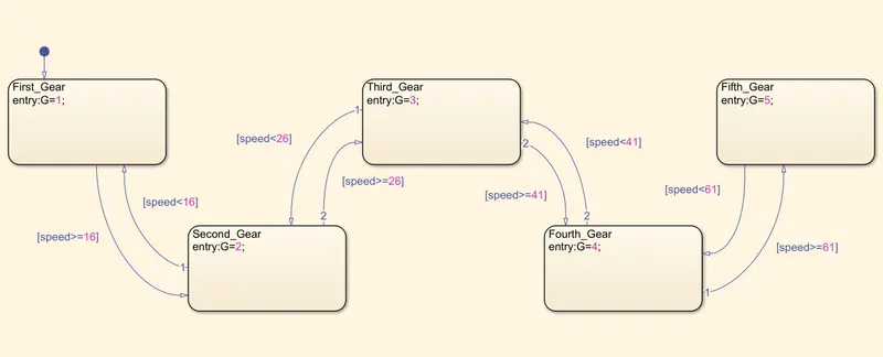
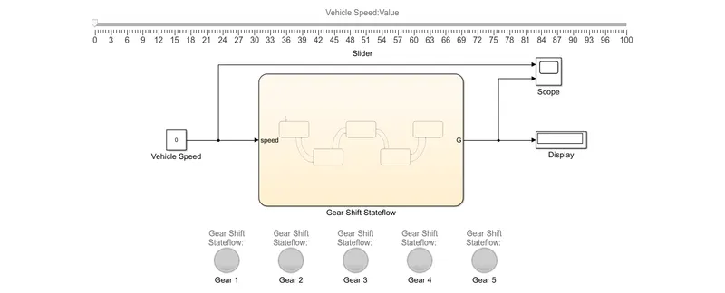
Fig 3. Gear Shift Overview
EXPLANATION:
- Here, we going to design the model of gear shift to run in the certain conditions as given
- So first we have to design a stateflow of the gear shift with 5 gear transmission
- Use the chart block to construct the stateflow. On above Fig 2 has the snapshot of this stateflow, it's fully constructed by the 0 and 1 values
- Use the state option to construct the each processes of the gear shift, then connects all the blocks through the transition line
- After the design of each blocks in the stateflow, apply the given conditions as to run the each process as in the certain amount of speed
- Now exit from the stateflow and give the input of vehicle speed by using constant block and connect that block with the slider to control the vehicle speed
- Then connects the output of the G (gear) from the stateflow to the display as respectively and also connect the scope with the output to analyze the input and output
- And use 5 lamp blocks and connect all those in the stateflow block for the indication of the gear position
- Then set all the gear lamp indicators as per the position of the gear by order
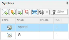
- Finally, set the stop time (inf), before the program run, check the port numbers in the symbols pane on the stateflow for once which in the toolstrip bar
CONCLUSION:
- As per the given condition, both models achieved thier solution
- From this model design, the working of stateflow concept has learned successfully
- Well aware of the uses of lamp and slider blocks