Week-7 Challenge: DC Motor Control
AIM:
Explain the following:
- A. Explain a MATLAB demo model named ‘Speed control of a DC motor using BJT H-bridge’
B. Comment on the armature current shoot-up from the scope results
C. Refer to the help section of ‘The Four-Quadrant Chopper DC Drive (DC7) block’. Compare it with the H-bridge model - Develop a 2-quadrant chopper using simulink & explain the working of the same with the relevant results (Refer to article - Multiquadrant operation of motor )
- Explain in a brief about operation of BLDC motor
OBJECTIVE:
- Prepare the program in matlab for the given requirement
- Ensure the output of the program
- Compare and expalin about the given model
- Prepare model through simulink as per the requirement
- Explain the mentioned component as brief
1. a) EXPLAIN A MATLAB DEMO MODEL NAMED ‘SPEED CONTROL OF A DC MOTOR USING BJT H-BRIDGE’
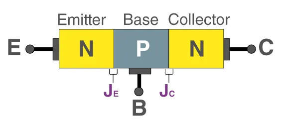
Bipolar Junction Transistor - BJT:
A bipolar junction transistor is a three-terminal semiconductor device that consists of two p-n junctions which are able to amplify or magnify a signal. It is a current controlled device. The three terminals of the BJT are the base, the collector, and the emitter. A signal of a small amplitude applied to the base is available in the amplified form at the collector of the transistor. This is the amplification provided by the BJT. Note that it does require an external source of DC power supply to carry out the amplification process
Note: The combination of MOSFET and BJT is IGBT
Model:
Explanation:
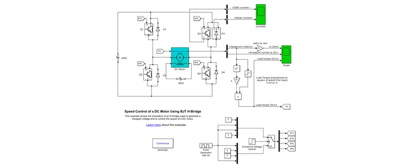
- From this above model, the initial source has got from the block of DC voltage source as 240V, then it has connected with the "H-bridge rectifier"
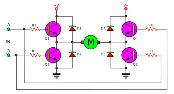
- Usually H-bridge is an electronic circuit that switches the polarity of a voltage applied to a load, It has mostly used in motor controllers, particularly a bipolar stepper motor is almost always driven by a motor controller containing two H bridges
- The H-bridge contains the 4 transistors of IGBT (Insulated-gate bipolar transistor) and with 4 diodes parallel to the transistors as respectively
- By getting this IGBT block, search as 'IGBT' in the simulink library
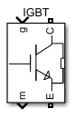
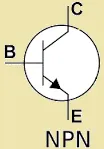
- In this IGBT transistor has used the NPN type, which means p-type semiconductor is sandwiched between the two n-type semiconductors. The two n-type semiconductors act as emitter and collector respectively while the p-type semiconductor acts as a base
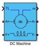
- Here all the transistors has connected in the DC machine were placed between the H-bridge connections and the seperate battery pack of 300V has connected with DC machine by the DC voltage source block
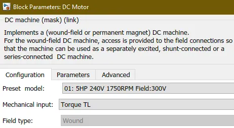
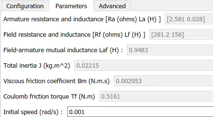
- The Inputs of DC machine as follows:
Preset model.No: 01 and Initial speed: 0.001 rad/s
- The pulse generator block has used to pass the signal as per the quadrants operation and mux block has used to connect the required inputs
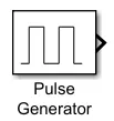

- The two seperated muxs connected to the switch block were one is in the input1 and another mux in the input2
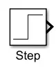
- The step block has used to control the armature voltage by giving the step time and threshold value (in switch block) as 0.5
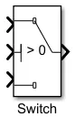
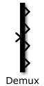
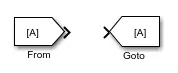
- Then the single output of switch block has passed to the demux block as out by 4 outputs. These are the signal inputs of the transistors used and they are used the goto blocks to send signals to from blocks were connected in the transistors with the specified tag
- The final output of the DC machine has passed to the bus connector block, it shows the output element by choosing the given option in the block
- We have choose the speed and armature current to show as an output in the scope
- Before that, speed output have to multiply by fan type value - (30/`pi`) in the gain block
- To find the load torque of motor, design a function (`k*omega^2`) by gain and math or square blocks and the `k` value as 6.062e-4 and `omega` is getting from the speed output of motor
- Then use the signum block to make the values as positive, so multiply the designed function with this signum block by using product block
- And the output of this product has passed to the DC machine through goto block and this load torque output has send to the same scope were motor speed output connected
- For the reference, the current flow of IGBTs and diodes has connected with the seperate scope through the bus connector as respectively
- Here the powergui block has used for the continuous variable-step solver, which means usually the step time, sample time may varies in the chopper configuration, at the time we use this block to correct the time allots which gives a optimal performance
1. b) COMMENT ON THE ARMATURE CURRENT SHOOT-UP FROM THE SCOPE RESULTS
Armature Current Shoot-Up:
It is nothing but in the certain period a sudden high current passed through the armature windings has makes some fluctuation which is look like a small up and down in the readings
Case I - The armature current shoot-up at 75% of period
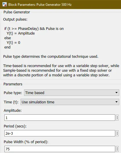
- Based on the input of pulse generator, the armature current of shoot-up has varies
- The above block parameters dialog box has shows the pulse width entered as 75%
- Following graph will shows the deviation of shoot-up in the armature current by the entered value
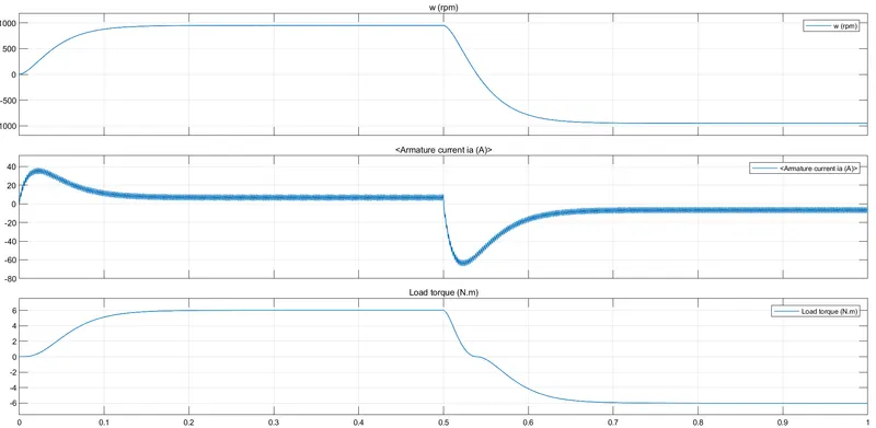
Note: From the x-axis on 0.5, the deviation starting goes down from 10A upto -70A and after it gradually increasing back to the rest position till the end of the reading
Case II - The armature current shoot-up at 30% of period
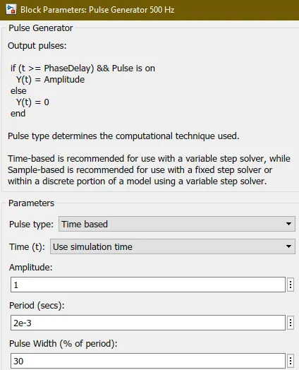
- Here we made a changes in the pulse width input on pulse generator which is entered as 30%. So this shows the comparison between these two graphs
- Because it's an input changes in the initial source, it definitely affect the output were shown below
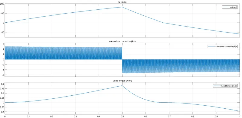
Note: Based on the pulse width input, the armature current reading limit on y-axis has reduced, Now it shows a sudden impacts then the before one
1. c) REFER TO THE HELP SECTION OF ‘THE FOUR-QUADRANT CHOPPER DC DRIVE (DC7) BLOCK’. COMPARE IT WITH THE H-BRIDGE MODEL
- By the help section reference, I have got the DC7 - Four-Quadrant Chopper 200 HP DC Drive
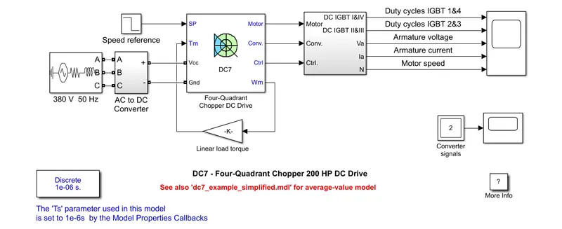
Comparison between H-Bridge & 4 Quadrant Model:
From this above model, the comparison has detailed below,
Power Source:
- In BJT H-bridge, there is single phase power sources (240V and 300V) has only used for both transistors and DC machine
- But in 4 Quadrant Chopper DC, it has powered by three phase DC source (380V and 50Hz) for whole DC drive
Chopper Configuration:
- BJT H-bridge has used the seperate block for DC drive connection for each process like DC motor/machine and transistors(H-bridge)
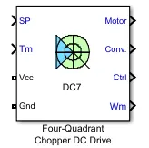
- But in this 4 Quadrant DC Chopper, "4 quadrant chopper DC drive" block has implemented, it holds the 3 sections of DC machine, converter and controller inside a single one. So there is no need add the seperate transistor block like before used in the BJT H-bridge
Input Signal:
- In BJT H-bridge, the initial input has passed by the pulse generator block as per the quadrants operation and mux block has used to connect the required inputs to the DC machine
- In 4 Quadrant Chopper DC, the step block has used to fed the input signal as per the DC drive used
Power Convertor:
- BJT H-bridge has used the transistors to control and converts the feeded current then passed to the DC motor
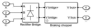
- But in 4 Quadrant Chopper DC, the converter has created by the set of sub-system which holds the programmed 'rectifier bridge' and 'braking chopper'
Powergui Selection:
- In BJT H-bridge, there is a continuous gui block has used for the continuous result in the output without the sample time error
- 4 Quadrant chopper DC used the discrete gui block for to fix the time step in the electrical system
Graph:
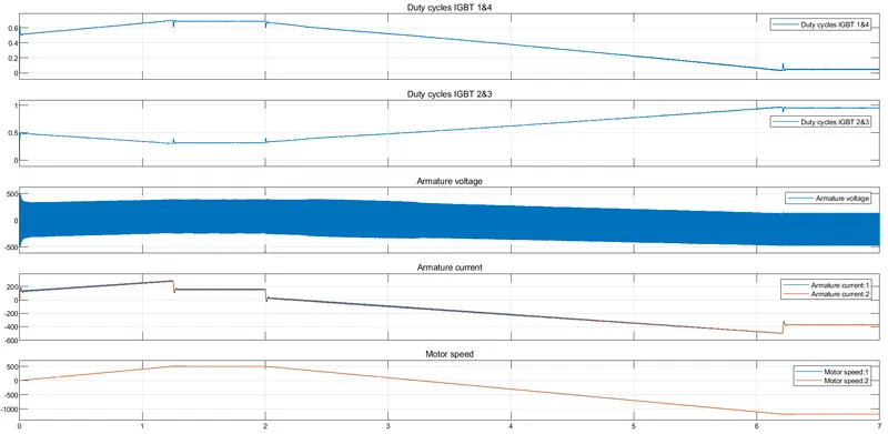
Result of four-quadrant chopper DC drive,
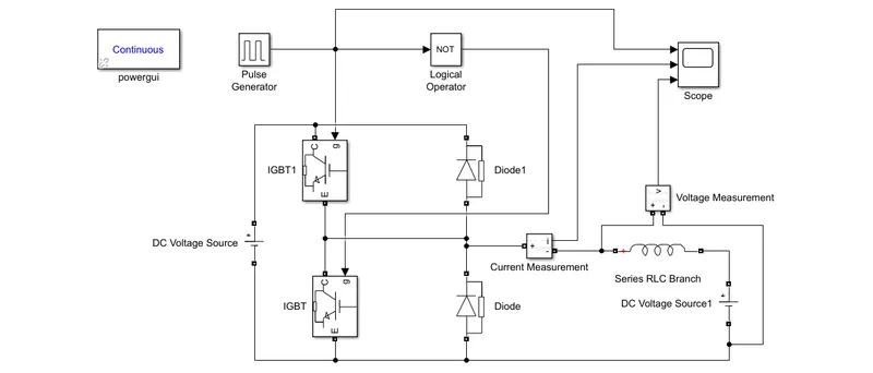
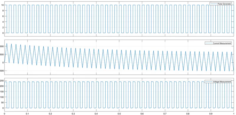
2. DEVELOP A 2-QUADRANT CHOPPER USING SIMULINK & EXPLAIN THE WORKING OF THE SAME WITH THE RELEVANT RESULTS
- Refer the given link for to design the model of "two quadrant chopper"
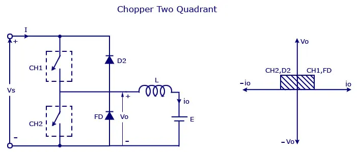
- The above mentioned image has gives a detail clarification from the link, based on this we can design the model of two quadrant chopper
Model:
Working Principle Explanation:
- From this model, the following blocks are used as major to the design the chopper, they are
1. IGBT and diode
2. Series RLC branch
3. Powergui
Resultant Graph:
3. EXPLAIN IN A BRIEF ABOUT OPERATION OF BLDC MOTOR
Brushless Motor:
- A brushless DC motor is also known as a BLDC motor or BL motor is an electronically commuted DC motor which does not have brushes
- The controller provides pulses of current to the motor windings which control the speed and torque of the synchronous motor. These types of motors are highly efficient in producing a large amount of torque over a vast speed range
- In brushless motors, permanent magnets rotate around a fixed armature and overcome the problem of connecting current to the armature. They are known for smooth operation and holding torque when stationary
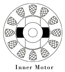
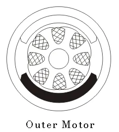
Types of Brushless DC Motors:
There are two types of BLDC motor, they are
- Outer rotor BLDC motor - can produce large amount of torque
- Inner rotor BLDC motor - operates at lower rated current & has low load torque
Mostly working principles are same, but the designs are only differs the both motors
BLDC Working:
-
Before explaining the working of a brushless DC motor, it is better to understand the function of a brushed motor. In brushed motors, there are permanent magnets on the outside and a spinning armature which contains electromagnet is inside
-
These electromagnets create a magnetic field in the armature when the power is switched on and help to rotate the armature. The brushes change the polarity of the pole to keep the rotation on of the armature
-
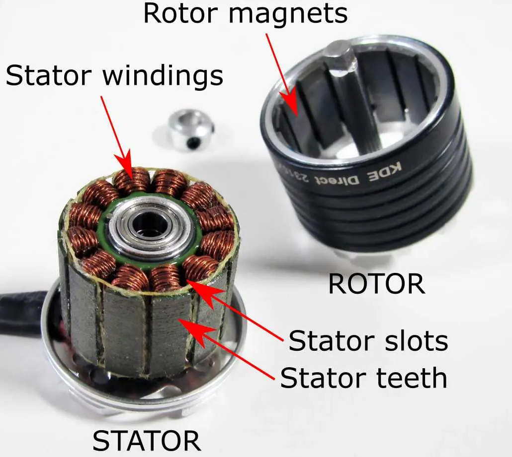
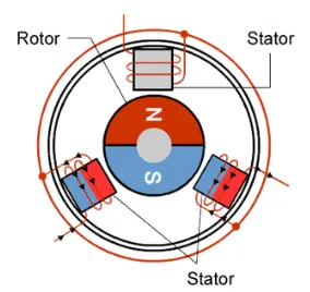
The basic working principle for the brushed DC motor and for brushless DC motor are same i.e. internal shaft position feedback. Brushless DC motor has only two basic parts: rotor and the stator
-
The rotor is the rotating part and has rotor magnets whereas stator is the stationary part and contains stator windings. In BLDC permanent magnets are attached in the rotor and move the electromagnets to the stator
-
The high power transistors are used to activate electromagnets for the shaft turns. The controller performs power distribution by using a solid-state circuit
Advantages:
- It can operate at high-speed under any condition
- It can accelerate and decelerate easily as they are having low rotor inertia
- BLDC can cooled by conduction and no air flow are required for inside cooling
- It is high performance motor that provides large torque and it's more efficient
Disadvantages:
- BLDC motor cost more than a brushed DC motor
- The limited high power could be supplied to BLDC motor, otherwise too much heat weakens the magnets and the insulation of winding may get damaged
REFERENCES:
- BJT H-bridge Overview: https://www.eleccircuit.com/basic-h-bridge-motor-driver-by-bipolar-transistor/
- The Four-Quadrant Chopper DC Drive (DC7) Overview: https://www.youtube.com/watch?v=26AJUvdVgLk&t=95s
- Multi Quadrant Operation of DC Motor: https://skill-lync.com/student-projects/multi-quadrant-operation-of-dc-motor-in-simulink
CONCLUSION:
- The mentioned demo model and it's scope result comment has explained
- Comparison of both quadrant models has done
- Model design through simulink has completed and explained
- The BLDC has learned and elucidated