Week-6 Challenge: EV Drivetrain
AIM:
To expalin the following:
-
Which types of power converter circuits are employed in electric and hybrid electric vehicle?
-
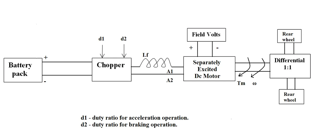
An Electric Vehicle's powertrain with 72V battery pack in shown in the diagram. The duty ratio for acceleration operation is 'd1' and for the braking operation the duty ratio is 'd2'(Diagram and initial parameters are given) and What is EV steady state speed if duty cycle is 70%?
-
Develop a mathematical model of a DC Motor for the below equation using Simulink.
`omega=V/(Kphi)-(R_a)/(Kphi^2)*T`
-
Refer to the blog on below topic and explain in brief about author’s perspective
OBJECTIVE:
- Explain the required given questions
- Evaluvate the given calculation about EV
- Create a model under the given equation in the simulink
- Refer the link and explain about it
1. TYPES OF POWER CONVERTER CIRCUITS ARE EMPLOYED IN ELECTRIC AND HYBRID ELECTRIC VEHICLE
Power Convertors:
-
Power converters are more properly called a voltage converter, this electrical device actually changes the voltage (either AC or DC) of an electrical power source. There are two types of voltage converters: step up converters (which increases voltage) and step down converters (which decreases voltage)
-
The most common use of a converter is to take a relatively low voltage source and step-it-up to high voltage for the heavy-duty work in a high power consumption load, but they can also be used in reverse to reduce voltage for a light load source
-
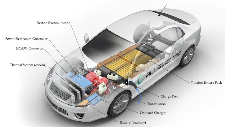
The converters are used by both EVs and hybrids to manage their electric drive systems. Along with a built-in charge controller, the converter supplies current to the battery pack for recharging during regenerative braking
-
And it also provides electricity to the motor/generator for vehicle propulsion. Both hybrids and EVs use relatively low-voltage DC batteries (about 210 volts) to keep the physical size down, but they also generally use highly efficient high voltage (about 650 volts) AC motor/generator
-
Because of the use of transformers and semiconductors enormous amounts of heat are emitted by these devices. Adequate cooling and ventilation are paramount to keeping the components operational.
- For this reason, inverter/converter installations in hybrid vehicles have their own dedicated cooling systems, complete with pumps and radiators, that are entirely independent of the engine's cooling system
Types Of Power Convertors Used In EV & HEV:
Depending on the type of function performed, power electronic converters are categorized into following types.
- AC to DC = Rectifier: It converts AC to unipolar (DC) current
- DC to AC = Inverter: It converts DC to AC of desired frequency and voltage
- DC to DC = Chopper: It converts constant to variable DC or variable DC to constant DC
1. AC to DC Converter (Rectifier):
- In EV, this type of AC-DC converter has used to converts the currents AC to DC during 'On-board charger'. And for the saftey reasons, the battery converter has to be isolated, so that there is an isolation happens between the battery and the AC grid. It's a single way process
2. DC to AC Converter (Inverter):
- In EV, the AC-DC type converter has used to converts the currents DC to DC during 'battery converter'
- These converters are connected between DC source of fixed input, and variable AC load. Most commonly, these DC to AC converters are called as inverters. An inverter is a static device that converts fixed DC supply voltage to variable AC voltage
- This battery converter must be bi-directional and it acn be either isolated nor non-isolated
3. DC to DC Converter (Chopper):
- A simplified step-down converter might work by generating a series of on-off pulses, and then using a combination of inductors and capacitors to smoothen this into a consistent DC signal, whose current is constant and whose voltage is determined by the duty cycle (that’s the duration of ‘on’ states relative to “off” ones)
- Many DC operated applications need different levels of DC voltage from a fixed DC source and EV and HEV are require variable DC to produce variable speed, so a power conversion device is needed
2. FIND EV STEADY STATE SPEED IF DUTY CYCLE IS 70% BY THE GIVEN PARAMETERS OF EV
Given Data:
Motor and Controller Parameters:
Rated Armature voltage,V = 72 V
Rated armature current,Ia = 400 A
Ra = 0.5Ω, KΦ = 0.7 Volt second
Duty cycle = 70%
The vehicle speed-torque characteristics are given by the below equation
`T_v=24.7+(0.0051)w^2`
T find:
To find the steady state speed(`omega`) for 70% of duty cycle
Given Model:
Evaluvation:
Duty cycle,`D_c` = 70% = 0.7
- Full Voltage of given battery pack is 72V, but we need now the battery only for 70% of duty cycle, so
New voltage,Vn = duty cycle (`D_c`) * given battery pack (V)
Vn = 0.70*72 = 50.4V
- Condition is, Vehicle Torque = Motor Torque
Tv = Tm
- Therefore the vehicle torque is,
Tv = 24.7 + 0.0051*w^2
- Now calculate Tm,
Tm = ((Vn*K)/Ra)-((w*(K^2))/Ra)
= ((50.4*0.7)/0.5)-((w*(0.7^2))/0.5)
Tm = 70.56-0.98*w
- Equating Tv = Tm,
24.7 + 0.0051*w^2 = 70.56-0.98*w
0.0051*w^2+0.98*w+24.7-70.56 = 0
0.0051*w^2+0.98*w-45.86 = 0
- Now use the quadratic equation to find the `omega` as easily,
`x = -b +- (√(b2 − 4ac))/(2a)`
- therefore substitute these below values in the above quadratic equation,
a = 0.0051
b = 0.98
c = -45.86
Case I: Use the positive quadratic equation
`omega` = -0.98+√(0.98^2 − 4*0.0051*(-45.86))/2*0.0051 = -0.98+1.3769/0.0102
= 0.3969/0.0102
`omega`= 38.91 rad/s
Case II: Use the negative quadratic equation
`omega` = -0.98-√(0.98^2 − 4*0.0051*(-45.86))/2*0.0051 = -0.98-1.3769/0.0102
= -2.3569/0.0102
`omega`= -231.06 rad/s
Solution:
Finally, based on the above two cases, the positive output only can be accepted as the value of speed. So the EV steady state speed for 70% of duty cycle is 38.91 rad/s
3. DEVELOP A MATHEMATICAL MODEL OF A DC MOTOR FOR THE GIVEN EQUATION USING SIMULINK
Used Inputs:
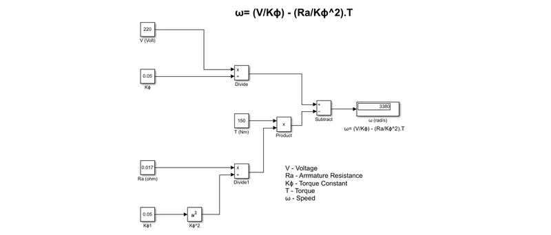
Voltage,V = 220 V
Armature Resisitance,Ra = 0.017 ohm
Torque,T = 150Nm
Torque Constant, K`phi`= 0.05
Model:
Explanation:
- The following will expalins about the DC motor Speed calculation has made in the simulink
Step 1: All the inputs are feeded by only the constant blocks
Step 2: Divide the Voltage (V) and Torque constant (K`phi`) by using divide block
Step 3: Square the another torque constant by square block
Step 4: Then divide the armature resistance (Ra) and squared torque constant (K`phi^2`) by using divide block and multiply it with the Torque (T) by using product block
Step 5: Finally the speed (`omega`) output which is dispalyed has got by subtracting (V/K`phi`) with (Ra/K`phi^2`)*T by using subtract block
4. REFER THE GIVEN BLOG EXPLAIN IN BRIEF ABOUT AUTHOR’S PERSPECTIVE
- The analysis has made based on the given link,
Induction Versus DC Brushless Motors
- Wally Rippel is the major suppoerter for Electric vehicle during his service in Tesla Motors
- He has supported and developed the GM - EV1 and worked in a feature documentry of Who Killed the Electric Car?
- By the rememberig of slide rule, there were lead acid batteries, DC brush motors and contactor controllers. Today, none of these remain, because lead has been replaced by lithium and DC by either DC brushless or induction and Contactors have given way to modulating inverters
- Both DC brushless and induction drives use motors having similar stators. Both drives use 3-phase modulating inverters. The rotors, inverter controls and the digital controllers are only different and the only control differences are with control code
- Following has detailed about Brushless DC and Induction Motor:
Brushless DC:
| SL.NO | BRUSHLESS DC | INDUCTION MOTOR: |
| 1 | The rotor includes two or more permanent magnets that generate a DC magnetic field | The induction rotor has no magnets just like stacked steel laminations with buried peripheral conductors that form a shorted structure |
| 2 | This magnetic field enters the stator core and interacts with currents flowing within the windings to produce a torque interaction between the rotor and stator. The device that provides this current control is called an inverter. Without it, brushless motors are useless motors | The frequency of this magnetic field as seen by the rotor is equal to the difference between the applied electrical frequency and the rotational frequency of the rotor itself |
| 3 | The brushless drives require an absolute position sensor | The difference are relatively small, so that the induction drives require only a speed sensor |
| 4 | Less rotor heat is generated with the DC brushless drive. Rotor cooling is easier and can also operate at unity power factor, whereas the best power factor for the induction drive is about 85 %, so that peak point energy efficiency is few points higher than for an induction drive | But Induction drive is not like that, it produce quite more heat than the DC brushless drive and also an induction drive peak point energy efficiency is few points lower than for DC brushless drive, but average efficiency may actually be better |
| 5 | The strength of the magnetic field produced by the permanent magnets would be adjustable. When maximum torque is required, especially at low speeds, the magnetic field strength should be maximum, so that inverter and motor currents are maintained at their lowest possible values | The inverter can reduce voltage such that magnetic losses are reduced and efficiency is maximized. Thus, the induction machine when operated with a smart inverter has an advantage over a DC brushless machine – magnetic and conduction losses can be traded such that efficiency is optimized |
| 6 | In DC brushless drive, Permanent magnets are expensive – something like $50/Kg. Permanent magnet (PM) rotors are also difficult to handle | This means that induction motors will likely retain a cost advantage over PM - DC brushless drive machines |
| 7 | DC brushless drive are easy to control. The control laws are not diffucult and complex to understand than the induction motor | Induction machines are more difficult to control. The control laws are more complex and difficult to understand |
| 8 | DC brushless drives will likely continue to dominate in the hybrid and coming in the plug-in hybrid vehicles | Induction drives will likely maintain dominance for the high-performance of pure electric vehicles |
CONCLUSION:
- The Power converter circuits types has understood well
- The steady state speed for 70% duty cycle has calculated
- Modelling the DC motor speed calculation through simulink has achieved
- Given topic has explaind by the reference blog