Week 7 State of charge estimation
AIM:
To explain the following:
- Simulate the 3 test cases from harness dashboard and write a detailed report on the results
- What is coulomb counting? Refer to the above model and explain how BMS implements coulomb counting for SOC estimation?
OBJECTIVES:
- Identify the appropriate model
- Analyze the blocks were used in the model
- Test 3 cases separately and prepare a reports
- Give a detailed explanation for the required questions
File download link - https://in.mathworks.com/matlabcentral/fileexchange/72865-design-and-test-lithium-ion-battery-management-algorithms
1. Simulate the 3 test cases from harness dashboard and write a detailed report on the results
Now we going to stimulates the three test cases of the "Battery Management System closed loop from Harness Dashboard" to accurately simulate dynamic behavior of single battery cell using simulink and scale the models all the way to perform system level simulation of entire battery pack
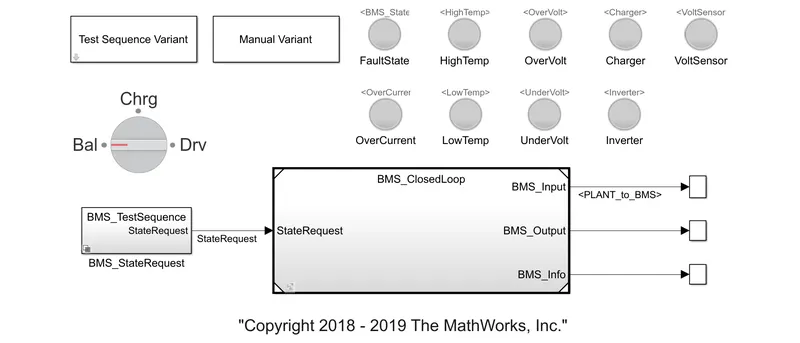
Following are the steps has followed to simulate the above BMS model as per each test cases,
TEST CASE 1
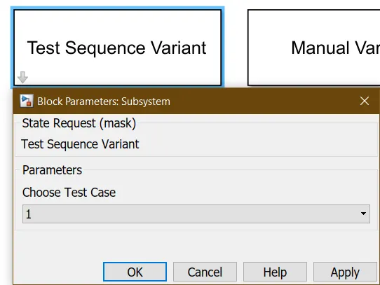
Step 1 - Double click to open the 'Test Sequence Variant' option, then select the "test case 1" and click apply
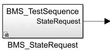
Step 2 - Select the 'BMS test sequence' block to check the 'Test sequence-1 chart'
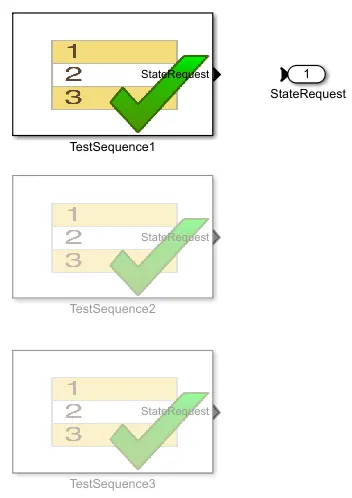
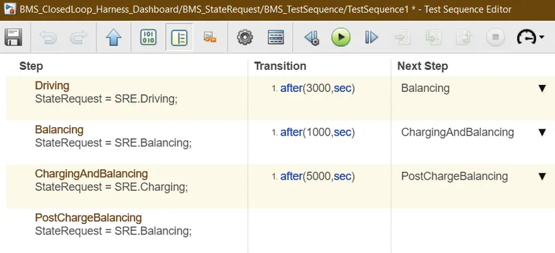
Here the test sequence 1 chart,
From the chart,
- On simulation begin time, The vehicle has starts with the driving condition for 3000 seconds
- After that balancing state continues for next 1000 seconds, which means the vehicle at standby condition
- Then on charging and balancing condition were runs for a 5000 seconds, this makes the vehicle to standby during the charging time upto 100% (referred SOC-1)
- After the charging completes, the vehicle has got standby for the rest of the vehicle runtime around 11000 seconds
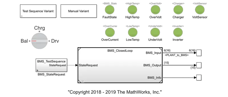
Test Case Model 1:
Graph:
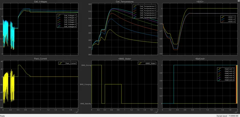
From the scope,
- During driving state, the vehicle driving begins at 80% (SOC) and ends at (referred SOC-3) ~45% (SOC). At this period,all the cell temperatures were increased gradually
- At balancing state, the entire battery pack has not gets that much deviation in their status for some period. Here 1st cell only gets the least values on all the graph readings
- On the charging and balancing state, the vehicle gets charged from ~45%. During this condition, the cell temperature gets fall because of the vehicle not in the driving condition
- At last of post charge balancing state, the vehicle has remains only at the standby condition. So all the cells 's temperature gets gradually fall down. And the voltage of all 6 cells has reached upto 4.2 V
- Based on the balancing command, all the 6 cells has maintained the standby position for last few seconds
TEST CASE 2
Step 1 - Double click to open the 'Test Sequence Variant' option, then select the "test case 2" and click apply
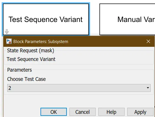
Step 2 - Select the 'BMS test sequence' block to check the 'Test sequence-2 chart'
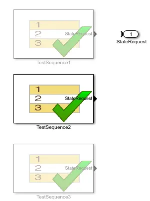
Here the test sequence 2 chart,
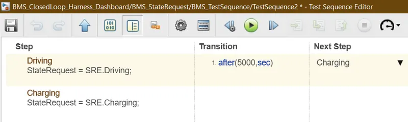
From the chart,
- On simulation begin time, the vehicle has starts with the driving condition and continues for 5000 seconds
- Then on charging condition were runs for a 1398 seconds, this makes the vehicle only for charging time upto 76% (referred SOC-1)
- During the charging period, the vehicle's BMS has got fault, and it remains for the rest of the vehicle runtime around 13600 seconds due to battery pack reaches high temperatures
Test Case Model 2:
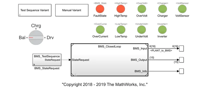
Graph:
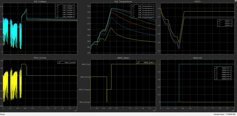
From the scope,
- During driving state, the vehicle driving begins at 80% (SOC) and ends at (referred SOC-3) ~32% (SOC). At this period,all the cell temperatures were increased gradually
- On the charging state, the vehicle gets charged from ~32%. During this condition, the cell temperature gets fall because of the vehicle not in the driving condition
- On the charge period, the cell pack has reached the high-level of temperature (over the limit). So that the BMS has got fault. Due to this errors, all the cells 's temperature gets gradually fall down
- The voltage of all 6 cells has reached upto 4.2 V and the cells never be in the standby condition during the entire runtime of the vehicle
TEST CASE 3
Step 1 - Double click to open the 'Test Sequence Variant' option, then select the "test case 3" and click apply
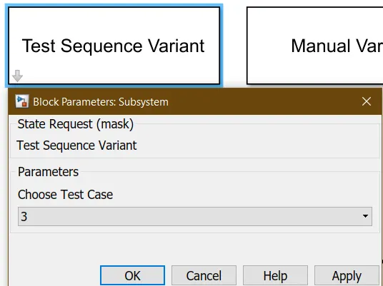
Step 2 - Select the 'BMS test sequence' block to check the 'Test sequence-3 chart'
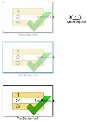
Here the test sequence 3 chart,
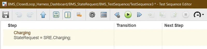
From the chart,
- On simulation , the vehicle has stayed only at the charging state during the entire runtime of the vehicle
- This sequence has shows there is no driving and balancing states happen in the vehicle
Test Case Model 3:
Graph:
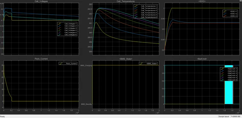
From the scope,
- During the charging state, the vehicle has got charged from 80% and it gets fully charged (referred SOC-1)
- On this condition, the cells temperature gets gradually increased upto the SOC reaches 100% (referred SOC-1) and those cells are again got falls because of the vehicle has got fully charged and after that the charger has got turned OFF as automatically
- Here the voltage of all 6 cells has reached upto ~4.1 V and the current remains 0A as respectively
- Based on the balancing command, all the 6 cells has maintained the standby position for last few seconds (~16000 to 18300th second)
2. What is coulomb counting? Refer to the above model and explain how BMS implements coulomb counting for SOC estimation?
Following has provided with the detailed information for the requirements,
Coulomb Counting:
- The coulomb counting (CC) is a technique used to track the State of Charge (SoC) and low calculation cost of a battery pack
- It works by integrating the active flowing current (measured in amps) over time to derive the total sum of energy entering or leaving the battery pack. This produces a capacity that is typically measured in Amp-hours
- However, in practical applications, the lack of error correction ability limits its accuracy due to the measured noise in the practical occasion
- The coulomb counting method is done to estimate the `SOC(t)`, which is estimated from the discharging current `I(t)` and previously estimated SOC values `SOC(t-1)`
SOC is calculated by the following equation,
`SOC(t)=SOC(t-1)+(I(t))/Q_n*Deltat`
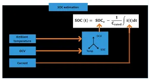
- But there are several factors that affect the accuracy of Coulomb counting method including temperature, battery history, discharge current and cycle life
Refer above 'BMS Closed Loop' model and explain how BMS implements coulomb counting for SOC estimation:
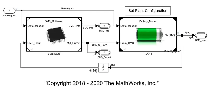
Following are the steps going to follows for implementing coulomb counting for SOC estimation in BMS,
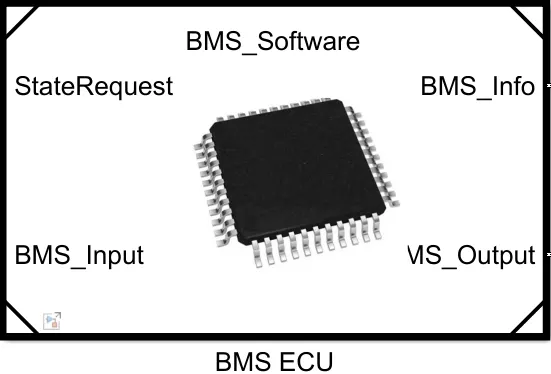
Step 1 - First, open the 'BMS ECU' subsystem
Step 2 - Followed by selecting the 'SOC Estimation' subsystem
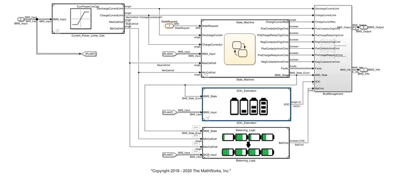
So as per SOC Estimation subsystem opens, we get
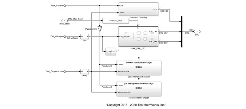
EXPLANATION:
1. Coulomb Counting:
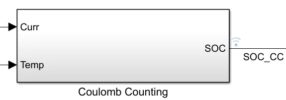
- In simulink, the CC has received the two inputs of current and temperature for the SOC estimation
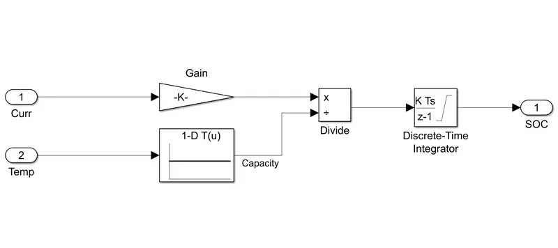
In coulomb counting (CC) subsystem,
- The current input has calculated with the gain block to gets the output in a specified gain factor
- The another input of temperature were passed to 1-D lookup table block to evaluate a sampled representation of a function in N variables
- Now both were calculated passed to the 'Discrete-Time Integrator' block which has placed in the integrator block to create a purely discrete model. Here the integrator method of output was 'Forward Euler' (`y(n) = y(n-1) + K*[t(n) - t(n-1)]*u(n-1)`) and the initial condition were set
2. Kalman Filter:
- Kalman filtering is an algorithm that provides estimates of some unknown variables given the measurements observed over time
- It have been demonstrating its usefulness in various applications. Kalman filters have relatively simple form and require small computational power
- However, it is still not easy for people who are not familiar with estimation theory to understand and implement the Kalman filters
- Kalman filters are used to estimate states based on linear dynamical systems in state space format
- Using real-time measurement road data to estimate the SOC of battery would normally be difficult or expensive to measure
- An extended Kalman filter (EKF) is to estimate the concentrations of the main chemical species which are averaged on the thickness of the active material in order to obtain the SOC of the battery, by using the terminal current and voltage measurements
- The UKF method is superior to extended Kalman filter method in SOC estimation for battery. An adaptive UKF method to estimate SOC of a lithium-ion battery for battery electric vehicles
- The adaptive adjustment of the noise covariance in the SOC estimation process is implemented by an idea of covariance matching in the UKF context
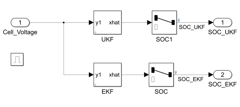
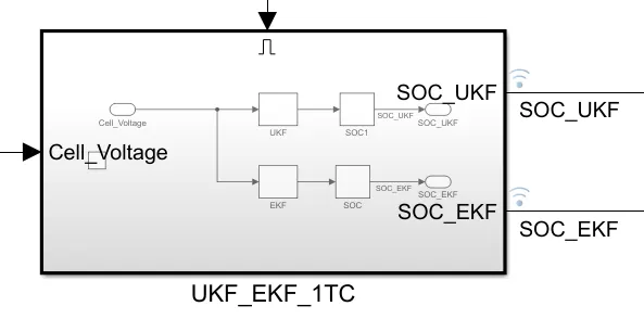
In Kalman Filter (KF) Subsystem,
- In UKF, a dynamics model describing object's motion and it is the optimal algorithm for its state estimation if the model of the system is linear and when disturbances of the process and measurements errors are additive and Gaussian
- The cell voltage from the cell pack has passed to the 'unscented kalman filter' block to estimates the states of a discrete-time nonlinear system using the discrete-time unscented Kalman filter algorithm
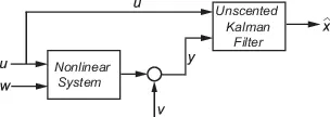
- Consider a plant with states x, input u, output y, process noise w and measurement noise v. Assume that you can represent the plant as a nonlinear system
- The output for the current step has produced with the help of state transition and measurement functions of the system and the unscented kalman filter algorithm
- In EKF, most systems of interest the dynamics and observation equations are non-linear. When at least one of the equations describing the system is non-linear, the Kalman Filter cannot be applied. Therefore, suboptimal non-linear filtration algorithms such as an extended kalman filter (EKF) have been developed
- In EKF, the non-linear functions are locally approximated with linear equations obtained from 'Taylor expansion'

- The extended kalman filter block has works similar like the unscented kalman filter block by the same process with some changes
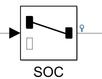
- And the both UKF and EKF block has handled by using the 'selector' block to generates the output by selected or reordered the elements of an input from those filters
- Finally, both results of the coulomb counting and kalman filter were passed to the SOC estimation to display the SOC status during the vehicle's three kind of states (driving, balancing and charging)
Coulomb Counting and Kalman Filter Combination:
- A new SOC estimation method, denoted as "KalmanAh method", which uses the Kalman filter method to correct for the initial value used in the Coulomb counting method
- In KalmanAh method, the Kalman filter method is used to make the approximate initial value converge to its real value
- Then the Coulomb counting method is applied to estimate the SOC for the long working time
- The SOC estimation error is 2.5% when compared with the real SOC obtained from a discharge test. This compares favorably with an estimation error of 11.4% when using Coulomb counting method
REFERENCES:
- SOC Estimation - https://www.youtube.com/watch?v=0v4IWgx83RA
- Understanding Kalman Filters - https://www.youtube.com/watch?v=mwn8xhgNpFY
CONCLUSION:
- The 3 test cases were simulated and reported as per the each vehicle conditions
- The implementation of coulomb counting for SOC estimation in BMS has explained