Project-1: Powertrain for aircraft in runways
AIM:
To explain the following:
Part A:
1. Search and list out the total weight of various types of aircrafts
2. Is there any difference between ground speed and air speed?
3. Why is it not recommended to use aircraft engine power to move it on the ground at Airport?
4. How an aircraft is pushed to runway when its ready to take off?
5. Learn about take off power, tyre design, rolling resistance, tyre pressure, brake forces when landing
Part B:
6. A. With necessary assumptions, calculate the force and power required to push / pull an aircraft by a towing vehicle
B. Develop the model for the calculated force and power using Simulink
7. A. Design an electric powertrain with type of motor, it’s power rating, and energy requirement to fulfill aircraft towing application in Simulink. Estimate the duty cycle range to control the aircraft speed from zero to highest. Make all required assumptions. Prepare a table of assumed parameters. Draw a block diagram of powertrain.
(Hint :DC7 Block)
B. Also, Design the parameters in excel sheet
OBJECTIVES:
- Explain the given topics with the detailed content
- Refer with the airticles for each
- Go through power and force calculation
- From the recall, calculate the force and power
- Execute the calculation in simulink
- Design an electric powertrain with acceptable inputs
1. Search and list out the total weight of various types of aircrafts
- The aircraft gross weight (also known as the all-up weight and abbreviated AUW) is the total aircraft weight at any moment during the flight or ground operation. An aircraft's gross weight will decrease during a flight due to fuel and oil consumption. An aircraft's gross weight may also vary during a flight due to payload dropping or in-flight refueling
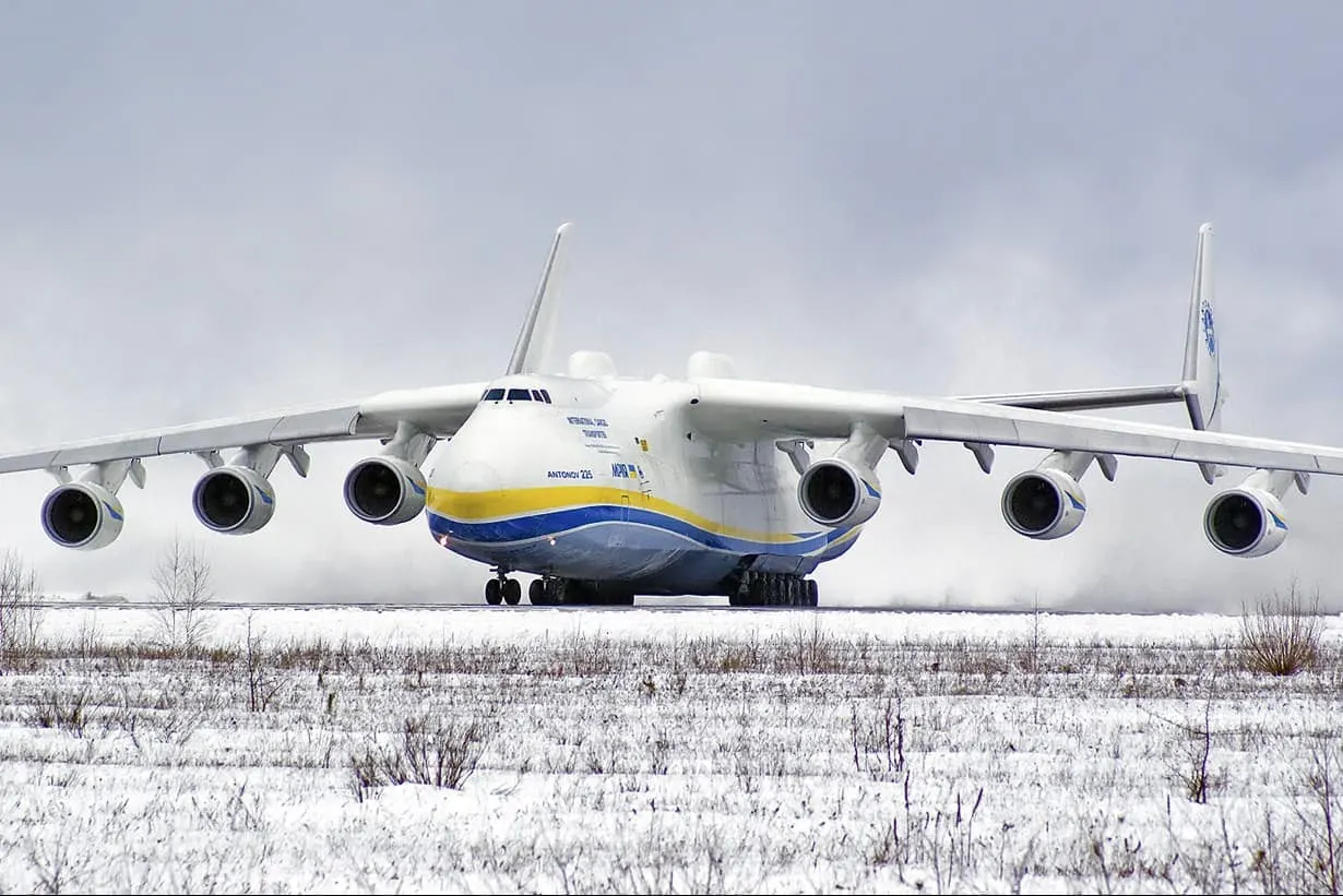
Figure-1: Antonov An-225 Mriya
- Now of releasing its brakes, the gross weight of an aircraft is equal to its takeoff weight. During flight, an aircraft's gross weight is referred to as the enroute weight or in-flight weight
DESIGN WEIGHT LIMITS (STRUCTURAL DESIGN WEIGHTS)
- An aircraft's gross weight is limited by several weight restrictions to avoid overloading its structure or to avoid unacceptable performance or handling qualities while in operation
- Aircraft gross weight limits are established during an aircraft's design and certification period and are laid down in the aircraft's type certificate and manufacturer specification documents. The absolute maximum weight capabilities of a given aircraft are referred to as the structural weight limits
- The structural weight limits are based on aircraft maximum structural capability and define the envelope for the CG charts (both maximum weight and CG limits)
- An aircraft's structural weight capability is typically a function of when the aircraft was manufactured, and in some cases, old aircraft can have their structural weight capability increased by structural modifications
MAXIMUM DESIGN TAXI WEIGHT (MDTW)
- The maximum design taxi weight (also known as the maximum design ramp weight (MDRW)) is the maximum weight certificated for aircraft maneuvering on the ground (taxiing or towing) as limited by aircraft strength and airworthiness requirements
MAXIMUM DESIGN TAKEOFF WEIGHT (MDTOW)
- Is the maximum certificated design weight when the brakes are released for takeoff and is the greatest weight for which compliance with the relevant structural and engineering requirements has been demonstrated by the manufacturer
MAXIMUM DESIGN LANDING WEIGHT (MDLW)
- The maximum certificated design weight at which the aircraft meets the appropriate landing certification requirements. It generally depends on the landing gear strength, or the landing impact loads on certain parts of the wing structure
- The MDLW must not exceed the MDTOW. The maximum landing weight is typically designed for 10 feet per second (600 feet per minute) sink rate at touch down with no structural damage
MAXIMUM DESIGN ZERO-FUEL WEIGHT (MDZFW)
- The maximum certificated design weight of the aircraft less all usable fuel and other specified usable agents (engine injection fluid, and other consumable propulsion agents)
- It is the maximum weight permitted before usable fuel and other specified usable fluids are loaded in specified sections of the airplane. The MDZFW is limited by strength and airworthiness requirements
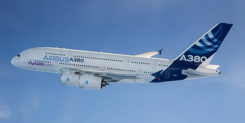
Figure-2: Airbus A380-800
- At this weight, the subsequent addition of fuel will not result in the aircraft design strength being exceeded. The weight difference between the MDTOW and the MDZFW may be utilized only for the addition of fuel
MINIMUM FLIGHT WEIGHT (MFW)
- Minimum certificated weight for flight as limited by aircraft strength and airworthiness requirements
AUTHORIZED WEIGHT LIMITS
- Aircraft authorized gross weight limits (also referred to as certified weight limits) are laid down in the aircraft flight manuals (AFM) and/or associated certificate of airworthiness (C of A). The authorized or permitted limits may be equal to or lower than the structural design weight limits
- The authorized weight limits that can legally be used by an operator or airline are those listed in the AFM and the weight and balance manual. The authorized (or certified) weight limits are chosen by the customer/airline, and they are referred to as the "purchased weights"
- An operator may purchase a certified weight below the maximum design weights because many of the airport operating fees are based on the aircraft AFM maximum allowable weight values. An aircraft purchase price is, typically, a function of the certified weight purchased
- Maximum weights established, for each aircraft, by design and certification must not be exceeded during aircraft operation (ramp or taxying, takeoff, en-route flight, approach, and landing) and during aircraft loading (zero fuel conditions, center of gravity position, and weight distribution)
- Weights could be restricted on some type of aircraft depending on the aircraft handling requirements; for example, aerobatic aircraft, where certain aerobatic maneuvers can only be executed with a limited gross weight
- In addition, the authorized maximum weight limits may be less as limited by center of gravity, fuel density, and fuel loading limits
MAXIMUM TAXI WEIGHT (MTW)
- The maximum taxi weight (MTW) (also known as the maximum ramp weight (MRW) is the maximum weight authorized for maneuvering (taxiing or towing) an aircraft on the ground as limited by aircraft strength and airworthiness requirements
- It includes the weight of taxi and run-up fuel for the engines and the APU. It is greater than the maximum takeoff weight due to the fuel that will be burned during the taxi and runup operations
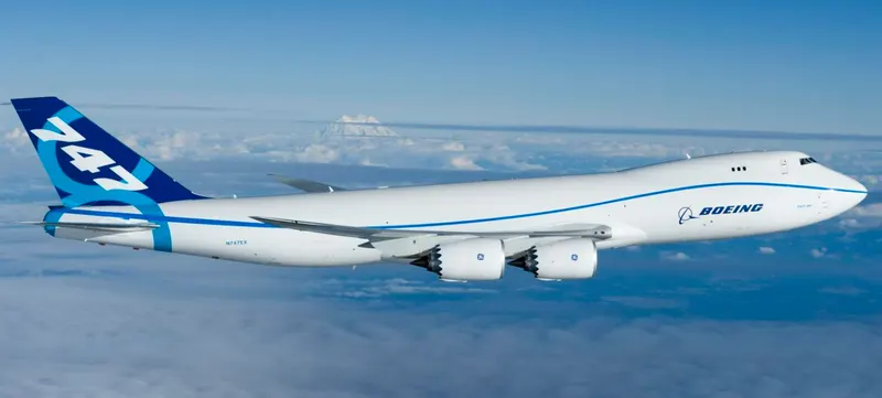
Figure-3: Boeing 747-8F
- The difference between the maximum taxi/ramp weight and the maximum take-off weight (maximum taxi fuel allowance) depends on the size of the aircraft, the number of engines, APU operation, engines/APU fuel consumption and is typically assumed for 10 to 15 minutes allowance of taxi and run-up operations
MAXIMUM TAKEOFF WEIGHT (MTOW)
- The maximum takeoff weight (also known as the maximum brake-release weight) is the maximum weight authorized at brake release for takeoff, or at the start of the takeoff roll
- The maximum takeoff weight is always less than the maximum taxi/ramp weight to allow for fuel burned during taxi by the engines and the APU
- In operation, the maximum weight for takeoff may be limited to values less than the maximum takeoff weight due to aircraft performance, environmental conditions, airfield characteristics (takeoff field length, altitude), maximum tire speed and brake energy, obstacle clearances, and/or en-route and landing weight requirements
MAXIMUM LANDING WEIGHT (MLW)
- The maximum weight authorized for normal landing of an aircraft. The MLW must not exceed the MTOW. The operation landing weight may be limited to a weight lower than the Maximum Landing Weight by the most restrictive of the following requirements
- Aircraft performance requirements for a given altitude and temperature:
Landing field length requirements, approach, and landing climb requirements
- Noise requirements:
If the flight has been of short duration, fuel may have to be jettisoned to reduce the landing weight. Overweight landings require a structural inspection or evaluation of the touch-down loads before the next aircraft operation
MAXIMUM ZERO-FUEL WEIGHT (MZFW)
- The maximum permissible weight of the aircraft less all usable fuel and other specified usable agents (engine injection fluid, and other consumable propulsion agents)
- It is the maximum weight permitted before usable fuel and other specified usable fluids are loaded in specified sections of the airplane
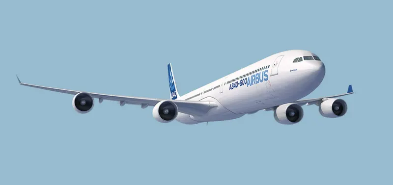
Figure-4: Airbus A340-600
Following will shows some varities of flight categories under MTOW and MLW,
| LIST OUT THE TOTAL WEIGHT OF VARIOUS TYPES OF AIRCRAFTS | ||||||
| Type | MTOW [kg] | MLW [tonnes] | TOR [m] | LR [m] | ICAO category | FAA category |
| Antonov An-225 | 640000 | 591.7 | 3500 | 3300 | Heavy | Super |
| Airbus A380-800 | 575000 | 394 | 3100 | 1930 | Super | Super |
| Boeing 747-8F | 447700 | 346.091 | 3100 | 1800 | Heavy | Heavy |
| Antonov An-124 | 405060 | 330 | 2520 | 900 | Heavy | Heavy |
| Boeing 747-400 | 396900 | 295.742 | 3018 | 2179 | Heavy | Heavy |
| Lockheed C-5 Galaxy | 381000 | 288.417 | 2530 | 1494 | Heavy | Heavy |
| Boeing 747-200 | 377840 | 285.7 | 3338 | 2109 | Heavy | Heavy |
| Boeing 747-300 | 377840 | 260.32 | 3222 | 1905 | Heavy | Heavy |
| Airbus A340-500 | 371950 | 240 | 3050 | 2010 | Heavy | Heavy |
| Airbus A340-600 | 367400 | 256 | 3100 | 2100 | Heavy | Heavy |
| Boeing 777F | 347800 | 260.816 | 2830 | 1860 | Heavy | Heavy |
| Airbus A330-900 | 352000 | 251.5 | 3100 | 1700 | Heavy | Heavy |
| Boeing 777-300ER | 351800 | 251.29 | 3100 | 1800 | Heavy | Heavy |
Where,
MTOW = Maximum take-off weight
MLW = Maximum landing weight
TOR = Take-off run
LR = Landing run
2. Is there any difference between ground speed and air speed?
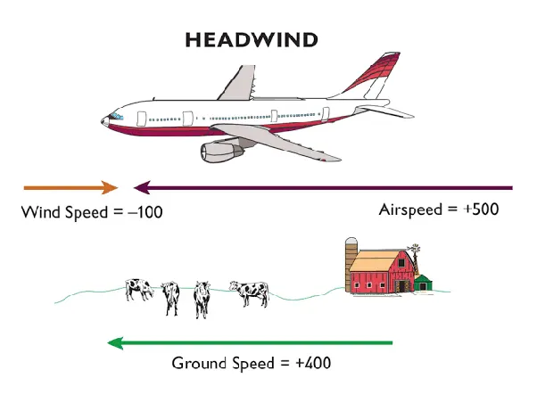
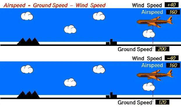
The relationship between airspeed and ground speed is fairly simple. Ground speed is simply the sum of airspeed and wind speed. If the aircraft is flying in the same direction as the wind is blowing, the aircraft experiences tailwind and its ground speed is higher than its airspeed
Ground Speed:
- The ground speed on the other hand is the aircraft’s speed relative to the ground. One thing that should be noted here is that it’s its horizontal rather than vertical speed – an aircraft climbing completely vertically would have a ground speed of zero
- The ground speed is what determines how fast an aircraft will get to its destination
Air Speed:
- The true airspeed is simply the speed at which an aircraft is moving relative to the air it is flying in. As such, it’s also the speed at which the air is flowing around the aircraft’s wings
- In other words, while airspeed is what determines whether there is enough airflow around an aircraft to make it fly
So,
- For pilots, both airspeed and ground speed are very important. While the first of those helps them make sure they are flying fast enough to take off, not to stall, and so on
- The second one helps them figure out how long it will take them to get from one place to another
- On the other hand, if you are a passenger, you will only need to be concerned about the ground speed as that will tell you how fast are you flying from your origin to your destination
3. Why is it not recommended to use aircraft engine power to move it on the ground at Airport?
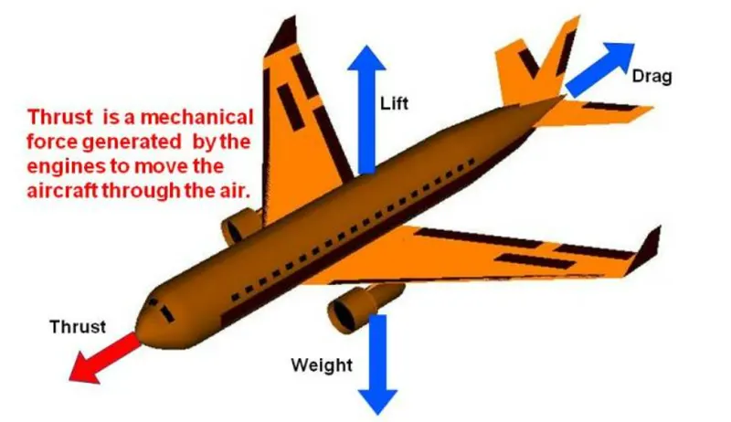
- Because the power of aircraft engine has makes high amount of thrust power in it
- High engine thrust during maintenance activity can cause considerable damage to airplanes and other elements in the airport environment. This problem occurred after an airplane arrived at its final destination with a log entry indicating the flight crew had experienced anomalous engine operation
4. How an aircraft is pushed to runway when its ready to take off?
By this following 10 steps will helps to know the procedure for aircraft take-off preparation,
Ready for take-off in ten steps…
- The pilot parks the aircraft in exactly the right place. Usually with the help of an automatic system, but occasionally guided by a marshaller waving two paddles or wands. Dozens of handling personnel are already standing by to perform a whole range of tasks simultaneously
- As soon as the aircraft is stationary and the engines are switched off, the first priority is to disembark the passengers as quickly as possible. The apron handler places chocks in front of the wheels and connects the ground power. Meanwhile, the passenger bridge manoeuvres up to the door and a belt loader rolls up to the cargo hold. Luggage is unloaded and transferred to the terminal on baggage carts
- Refuelling begins, usually from a hydrant at the stand. A hose is attached to this from a special vehicle called a dispenser, with the other side connected to the fuel tank in the wing. Read more about refuelling here
- Now it is time to service the aircraft. The caterer loads new meals and takes away the food waste and used cutlery and crockery. Other activities include draining the lavatories, replacing the headrest covers, removing rubbish and distributing fresh blankets and in-flight magazine
- A specialist team – or sometimes the crew themselves – cleans the cabin so that the new passengers board a pristine aircraft
- Meanwhile, specialists from the airline conduct a technical check to make sure that the engines, wings, control surfaces, landing gear, instruments, doors and other equipment are in full working order
- The aircraft is now ready for baggage to be loaded for the next flight. This is a quick process, on average taking only 10-15 minutes. A little later the passengers start boarding. As soon as they are all in their seats, the door is closed and the pilot informs air-traffic control that the flight is ready for departure
- The apron handler removes the chocks. A so-called pushback truck reverses the aircraft into taxiing position, pushing it with a towbar attached to the nose-wheel strut. Or, in the most modern versions, by actually lifting the wheel. That speeds up coupling and decoupling
- The aircraft taxis to the runway to depart at the agreed time
- The pilot waits for permission to take off from air-traffic control. This is possible once the departure route is clear. As soon as the go-ahead is received, the plane takes to the air at full power
May check the aircraft take-off procedure through the following links:
Here a smaller narrow-body jet can often depart again within just half an hour of landing. In the case of large wide-body aircraft, the process takes two to three hours. Either way, every successful turnaround is a top-class achievement in a whole range of ways
5. Learn about take off power, tyre design, rolling resistance, tyre pressure, brake forces when landing
Following will explain about the calculation parameters of the aircraft landing,
Take-off Power:
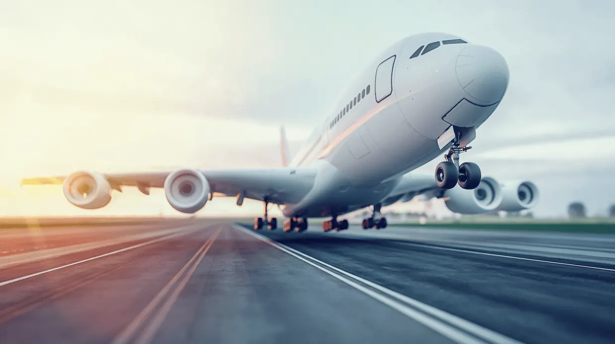
- Takeoff is the phase of flight in which an aircraft goes through a transition from moving along the ground (taxiing) to flying in the air, usually starting on a runway
- The amount of power that an engine is allowed to produce for a limited period of time for takeoff. The use of takeoff power is usually limited to 5 min for reciprocating engines and up to 2½ min for gas turbine engines
- This may not always be the case. Specifically, with respect to reciprocating engines, it is the brake horsepower developed under standard, sea-level conditions and under the maximum conditions of the crankshaft rotational speed and the engine manifold pressure approved for the normal take-off
- It is limited in continuous use to the period of time shown in the approved engine specifications. With respect to gas turbine engines, it is the thrust developed under static conditions at a specified altitude and atmospheric conditions of the rotor shaft rotational speed and gas temperature approved for the normal takeoff
- It is limited in continuous use to the period of time shown in the approved engine specifications
- For balloons, helicopters and some specialized fixed-wing aircraft (VTOL aircraft such as the Harrier), no runway is needed. Takeoff is the opposite of landing
Tyre Design:
- An aircraft tire or tyre is designed to withstand extremely heavy loads for short durations
- Designing aircraft tires is a very intense undertaking. Once an aircraft manufacturer goes to the tire manufacturer with the size and weight requirements, the tire manufacturer begins the process of designing a tire that meets the needs of the aircraft manufacturer as well as all regulatory requirements — including foreign regulations in many cases
- Engineers are challenged with designing tires with cool running, heat-resistant materials while simultaneously exceeding tire service requirements
- Tire prototypes are put through rigorous tests that simulate cycles of landings, take-offs, and taxi operations. It is only after the tires pass all mandatory tests and meet the requirements of the aircraft manufacturer and airworthiness authorities that the tires are put into production
- Two types of tires are used in aircraft applications — bias-ply tires and radial tires. Although both types of tires share some similarities in design, there are differences that need to be noted
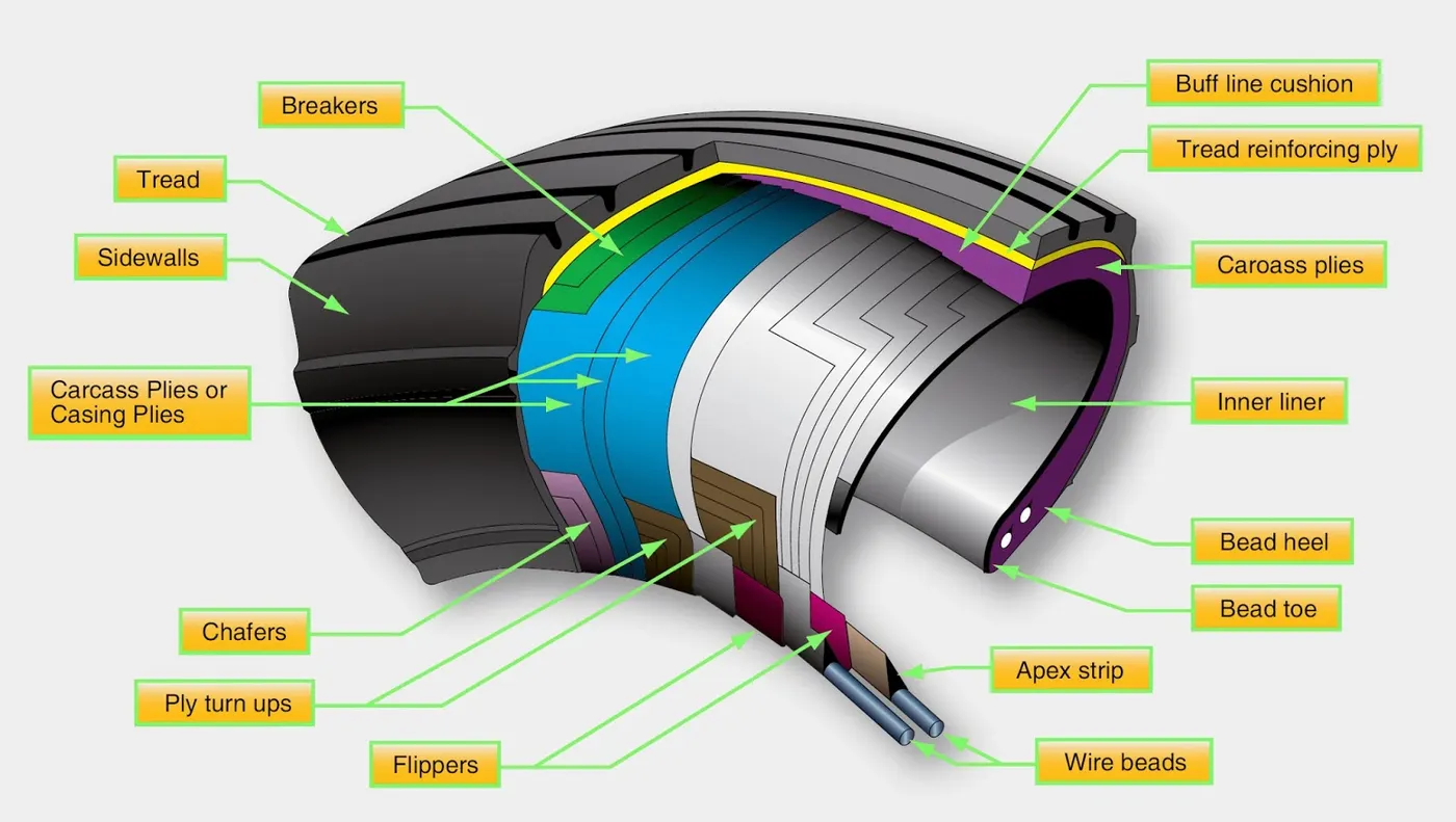
Let’s go through some technical aspects of the tyre,
- Retreading – Retreading is methods of restoring a worn tyre by renewing the tread area or by renewing the tread area plus one or both sidewalls. Repairs are included in the tyre retreading process
- Load Rating – Load rating is the maximum permissible load at a specified inflation pressure
- Ply Rating – Ply Rating is used to identify the maximum recommended load rating and inflation pressure for a specified tyre. It is an index of tyre strength
- Speed Rating – The speed rating is the maximum takeoff speed to which the tyre has been tested
- Skid Depth – Skid depth is the distance between the tread surface and the deepest groove as measured in the mould
Aircraft tyres must have an approved speed and load rating and have sufficient clearance when retracted through landing gear to allow for tyre growth. Tyre growth is the increase in the size of the tyre due to centrifugal forces at high speed.
Aircraft tyres may be Tube-type or Tubeless
- Tubeless tyres are more advantageous over tube-type. There is no longer the use of tube-type tyre in recent aviation. Nowadays all airliners are using tubeless tyres
- Tubeless that are meant to be used without a tube has the word TUBELESS on the sidewall of the tyre.
Aircraft tyres may be Radial or Bias
- Almost all airliners are using Radial tyre. Bias is an older design, and it’s mainly used for road vehicles. Radial tyres have the word RADIAL on the sidewall
- Radial tires are more expensive than bias-ply tyres. Radial tires are in demand because of their lower life cycle cost and long term value
Why are tyres important in Aircraft?
- When it comes to safety, tyres are one of the most important components of aircraft. They help to absorb the shock of landing and provide cushioning. It also provides the necessary traction for braking and stopping of an aircraft
- An aircraft tyre is designed to withstand extremely heavy loads while landing, take off, taxing, and parking. The number of wheels required for aircraft increases with the weight of the aircraft, as the weight of the aeroplane needs to be distributed more evenly
- A Boeing 737NG & 737MAX uses 6 wheels, Boeing 787 uses 10 wheels, Boeing 777 uses 14 wheels and Airbus A380 uses 22 wheels. Aircraft tyres work under extreme conditions, carrying up to 340 tons and accelerating at over 250 km/hour at takeoff, in addition to enduring varied environmental stress when in flight and taxiing
Rolling Resistance:
- Tire rolling resistance is the energy that your vehicle needs to send to your tires to maintain movement at a consistent speed over a surface. In other words, it is the effort required to keep a tire rolling. The main contributor to rolling resistance is the process known as hysteresis
- Hysteresis is essentially the energy loss that occurs as a tire rolls through its footprint. The energy loss must be overcome by the vehicle’s engine, which results in wasted fuel
Rolling Resistance Coefficient μR = F/G
Where,
F - Force necessary to pull the axle of a tire horizontally in the direction of travel
G - Vertical load on the tire which is assumed to roll on a flat horizontal surface
Tyre Pressure:
-
Of all the things that operators can do to improve the life of the aviation tire, maintaining good pressure maintenance is right at the top of every list. This article briefly explains why pressure maintenance is so important
-
No other tire has to deal with such high load and extreme speed as an airplane tire. So they need a bit more care than the tires on your car or motorcycle
-
Think of the role of the tire as holding the air at a pressure that is able to support the load of the airplane. (Nitrogen is normally used in commercial operations instead of air). Like all things aviation, the tire is one part of an assembly which can only work as intended when the parts are used as defined by the airframe and component manufacturers
-
Under-inflating the tire or allowing the tire to operate when it is under-inflated will prevent the parts working together as intended. And it will be the tire that will take the strain. It will deflect more and it will wear more. Harsh operating environments will only make it worse
- Some of the wear will be visible – on the tread and some of the wear will be invisible – inside the structure of the aviation tire
Visible Wear
- Under-inflation will increase the footprint of the aviation tire as it rolls on the ground and will increase the build-up of heat. Heat is no friend to tires on airplanes and the tread will wear out more quickly than it should
- On multi-tire landing gear the under-inflated tire will force the other, maybe correctly inflated tires, to take a little bit more of the strain. This will wear those other tires a little more.
Invisible Wear
- As extra heat caused by under-inflation builds up in the airplane tire the internal components of the tire might start to separate from each other. A catastrophic failure might result. Component separation in the casing of the tyre will prevent retreading and will increase operating costs. All for a bit of pressure maintenance
24 Hour Pressure Checks
- A carefully thought out pressure maintenance routine will increase the life of the tyre and will reduce the number of wheel changes required
- As all tires can allow a small pressure decrease during normal operations (due to the intense nature of their service life) airplane operators should check tire pressure every 24 hours. Because putting the right pressure in the tires will always take pressure off the airplane operation
Therefore,
- An aircraft tyre is designed to withstand extremely heavy loads for short durations. The number of tires required for aircraft increases with the weight of the aircraft, as the weight of the airplane needs to be distributed more evenly
- Aircraft tire tread patterns are designed to facilitate stability in high crosswind conditions, to channel water away to prevent hydroplaning, and for braking effect
- Aircraft tires generally operate at high pressures, up to 200 psi (14 bar or 1,400 kPa) for airliners, and even higher for business jets
- The main landing gear on the Concorde was typically inflated to 232 psi (16.0 bar), whilst its tail bumper gear tires were as high as 294 psi (20.3 bar). The high pressure and weight load on the Concorde tyres were a significant factor in the loss of Air France Flight 4590
- Tests of airliner aircraft tires have shown that they are able to sustain pressures of maximum 800 psi (55 bar or 5,500 kPa) before bursting
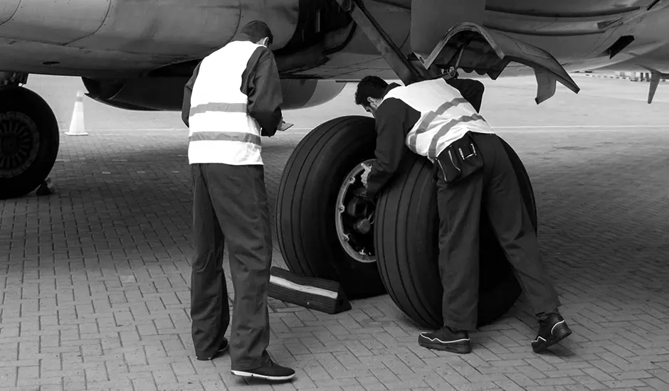
- During the tests the tires have to be filled with water, to prevent the test room being blown apart by the energy that would be released by a gas when the tire bursts
- Aircraft tires are usually inflated with nitrogen to minimize expansion and contraction from extreme changes in ambient temperature and pressure experienced during flight
- Dry nitrogen expands at the same rate as other dry atmospheric gases (normal air is about 80% nitrogen), but common compressed air sources may contain moisture, which increases the expansion rate with temperature
- The requirement that an inert gas, such as nitrogen, be used instead of air for inflation of tires on certain transport category airplanes was prompted by at least three cases in which the oxygen in air-filled tires had combined with volatile gases given off by a severely overheated tire and exploded upon reaching autoignition temperature
- The use of an inert gas for tire inflation eliminates the possibility of tire explosion
Brake Forces:
- Very early aircraft have no brake system to slow and stop the aircraft while it is on the ground. Instead, they rely on slow speeds, soft airfield surfaces, and the friction developed by the tail skid to reduce speed during ground operation
- Brake systems designed for aircraft became common after World War I as the speed and complexity of aircraft increased and the use of smooth, paved runway surfaces proliferated
- All modern aircraft are equipped with brakes. Their proper functioning is relied upon for safe operation of the aircraft on the ground
- The brakes slow the aircraft and stop it in a reasonable amount of time. They hold the aircraft stationary during engine run-up and, in many cases, steer the aircraft during taxi. On most aircraft, each of the main wheels is equipped with a brake unit. The nose wheel or tail wheel does not have a brake
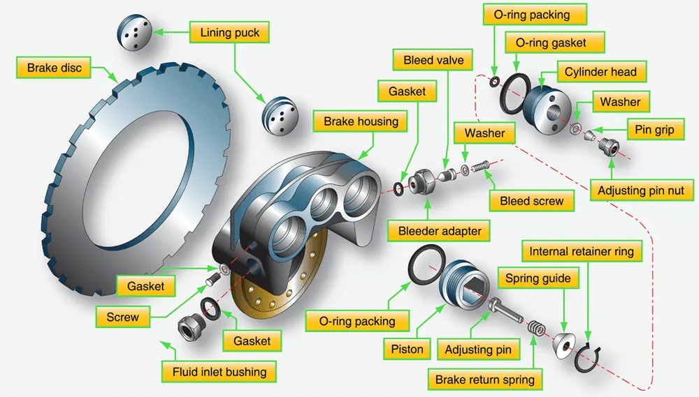
Types of Aircraft Brakes
They are,
- Single Disc Brakes
- Dua-Disc Brakes
- Multi-Disc Brakes
Segmented Rotor-Disc Brakes
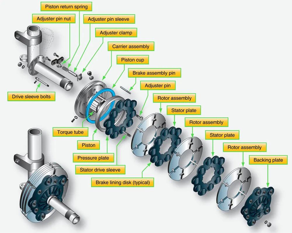
- The large amount of heat generated while slowing the rotation of the wheels on large and high performance aircraft is problematic. To better dissipate this heat, segmented rotor-disc brakes have been developed
- Segmented rotor-disc brakes are multiple-disc brakes but of more modern design than the type discussed earlier. There are many variations. Most feature numerous elements that aid in the control and dissipation of heat
- Segmented rotor-disc brakes are heavy-duty brakes especially adapted for use with the high pressure hydraulic systems of power brake systems
- Braking is accomplished by means of several sets of stationary, high friction type brake linings that make contact with rotating segments
- The rotors are constructed with slots or in sections with space between them, which helps dissipate heat and give the brake its name
- Segmented rotor multiple-disc brakes are the standard brake used on high performance and air carrier aircraft. An exploded view of one type of segmented rotor brake assembly
6. A) With necessary assumptions, calculate the force and power required to push / pull an aircraft by a towing vehicle
Kerb Mass:
Kerb mass is the weight of your vehicle with a fuel tank of fuel, but no accessories
Payload:
Payload is the weight of everything you can carry in or on the car. This includes you, passengers, accessories such as bull bar or tow bar and any cargo load
GVM:
Gross Vehicle Mass is the maximum the vehicle can weigh when fully loaded. This is the kerb weight plus the payload
Rolling Resistance:
- Rolling resistance is the combination of forces that work against the forward motion of your vehicle. The weight of the vehicle, gravity and inertia
- The amount of friction between the tires and the road surface and air drag all play a part. The more rolling resistance, the more power it takes to propel a vehicle
Aerodynamic Drag:
- Aerodynamic drag is the force needed to overcome these miniature forces when an object moves through air at a certain velocity. You can feel this force when you ride a bike
- The faster you travel, the more air you have to push through and the higher your induced drag
Note: To calculate this, you only need to know two key figures: the kerbweight of the car and the maximum mass of the caravan (called as "maximum technically permissible laden mass" or MTPLM)
Data:
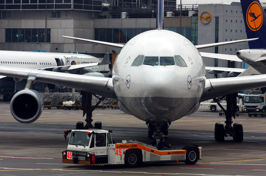
Reference Aircraft: Antonov An-225 Mriya
Payload weight of aircraft: 640000 kgs
Kerb wieght of towing vehicle: 544000 kgs
Coefficient of rolling resistance: 0.015
For aircraft, Coefficient of aerodynamic drag: 0.1
For towing vehicle, Coefficient of aerodynamic drag: 0.5
Air density: 1.25 kg/m3
Width: 7.1 m
Height: 21.26 m
Speed: 16.09 kmph
- Following will explain about the required calculations,
| Force & Power Calculation to Push/Pull an Aircraft by a Towing Vehicle | |
| Rolling Resistance Force Calculation (Frr) in N | |
| Kerb Weight - Towing Vehicle(kg) | 544000 |
| Payload - Aircraft (kg) | 640000 |
| Coefficient of rolling resistance | 0.015 |
| Rolling Resistance Force | 174048 |
| Aerodynamics Drag Force Calculation (Fad) in N | |
| Air density (kg/m3) | 1.25 |
| Width (m) | 7.1 |
| Height (m) | 21.26 |
| Frontal Area (m^2) | 150.95 |
| Drag coefficient | 0.18 |
| Speed (kmph) | 16.09 |
| Velocity (m/s) | 4.47 |
| Aerodynamics Drag Force | 339.22 |
| Total Tractive Force Calculation (Fte) in N | |
| Fte = Frr + Fad | 174387.22 |
| Power Calculation (Pte) in KW | |
| Pte = Fte * Velocity | 779.41 |
Note: The above calculation has calculated in excel and the workout file has attached with this project
6. B) Develop the model for the calculated force and power using Simulink
- Following has detailed the model of force & power through simulink,
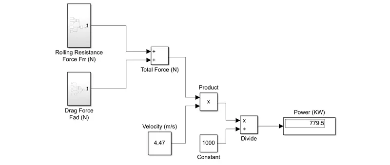
Note: The above devloped simulink model file has attached with this project
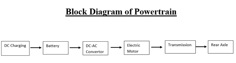
7. A) Design an electric powertrain with type of motor, it’s power rating, and energy requirement to fulfill aircraft towing application in Simulink. Estimate the duty cycle range to control the aircraft speed from zero to highest. Make all required assumptions. Prepare a table of assumed parameters. Draw a block diagram of powertrain
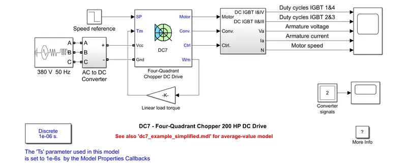
By this above reference used,
7. B) Design the parameters in excel sheet
| Energy & Duty Cycle Calculation | |
| Rolling Resistance Force Calculation | |
| Kerb Weight - Towing Vehicle(kg) | 544000 |
| Payload - Aircraft (kg) | 640000 |
| Coefficient of rolling resistance | 0.015 |
| Rolling Resistance Force (Frr) in N | 174048 |
| Aerodynamics Drag Force Calculation | |
| Air density (kg/m3) | 1.25 |
| Width (m) | 7.1 |
| Height (m) | 21.26 |
| Frontal Area (m^2) | 150.95 |
| Drag coefficient | 0.18 |
| Speed (kmph) | 16.09 |
| Velocity (m/s) | 4.47 |
| Aerodynamics Drag Force (Fad) in N | 339.22 |
| Total Tractive Force Calculation (Fte) in N | |
| Fte = Frr + Fad | 174387.22 |
| Power Calculation (Pte) in kW | |
| Pte = Fte * Velocity | 779.41 |
| Energy Calculation (E) in J | |
| Time for 1hour in seconds | 3600 |
| E = P*t | 2805890.367 |
| Duty Cycle | |
| Voltage (V) in Volts | 240 |
| Current (I) in Ams | 3.59 |
| Power Input (kW) | 862.53 |
| Duty Cycle = P(Out) / P(In) | 0.903636964 |
Note: The above calculation has calculated in excel and the workout file has attached with this project