Project 1
https://drive.google.com/file/d/1mD6cPruiQ11FLuCqwF6Ln_JQbO2X7xxB/view?usp=drive_web
AIM:
Extraction of mid surface and meshing the component dash board under the different quality criterias
SOFTWARE USED : ANSA v19.1.5
THEORY
Dash board is the part of the car which is located on the front side of the car . here many different parts are submerged and mounted in it . mostly the material is used is plastic as because of the airbags pierces through the plastic when accidents occurs and major part of the dashboard is seen in uniform of thickness and the components like AC vents are also attached to it .components like cluster and different modules are also attached to it

in the above fig the real image of dash board is shown
PROCEDURE
- The designed component is imported in to the ansa in the form of the igs format
- Material selection should be done for the given model
MATERIALS>DEFINED>OK
- Topo is used to convert the single cons in the image to the double and double are converted to the triple cons
(TOPO>FACES>TOPO)
- Geometry clean up:
Geometry clean up includes the checking the geometry its because while conversion of the file from another format geometrical errors are araised
(utlity>checks>geometry)
evaluation of errors
- The errors are resolved by going through the auto fix option
(checks>geometry>execute>select the errors> rightclick >auto fix)
Geometrical errors which are not resolved in the auto fix are to be resolved manually
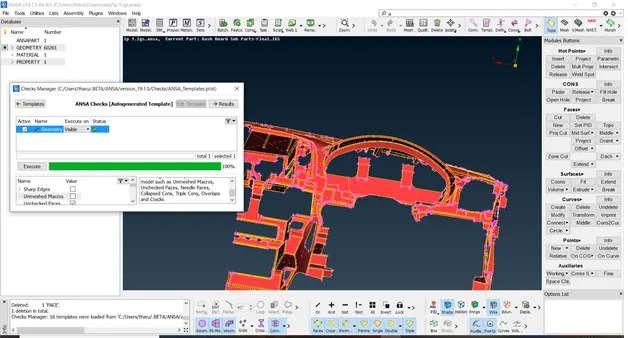
The above fig shows the perfect execution of the geometry
TRIPLE CONS:
these are formed only when the 3 surfaces are attached
(SELECT THE CONS>CONS>RELEASE>FACES>TOPO>CHECKS>GEOMTRY>EXECUTE>AUTOFIX THE CRACKS)
SINGLE CONS
- Single cons which are created are converted to double cons by creating a new surface
UNCHECKED ELEMENTS
- Unchecked which are evolved are fixed by creating a new surfaces at the fillet areas
- (topo>cons>fill hole>ok)
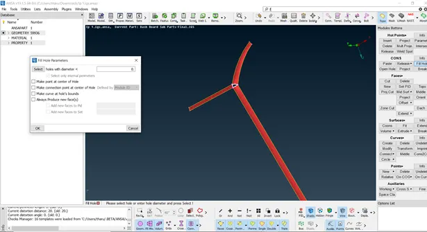
In the above fig Unchecked holes are closed by fill holes
MIDSURFACE:
Here are the 3d element is converted into the 2d element for the meshing generation of the midsurface
- OFFSET: The manual mid surface is to generate mid surface by selecting the individual surface of the model . midsurface here is obtained by divinding the thickness in to two halfs
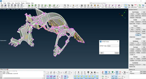
In the above fig application of the offset tool is shown
- After the generation of the 2d geometry the model is taken for the meshing but before undergoing through the meshing the model needs to get satisfiy the quality criterias
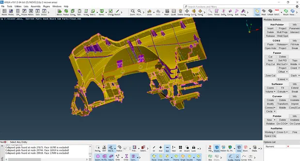
The above fig represents the overall midsurface of the dashboard
PID ELEMENTS
- The whole element is divided into the different number of the elements divided elements are useful to easily identify the
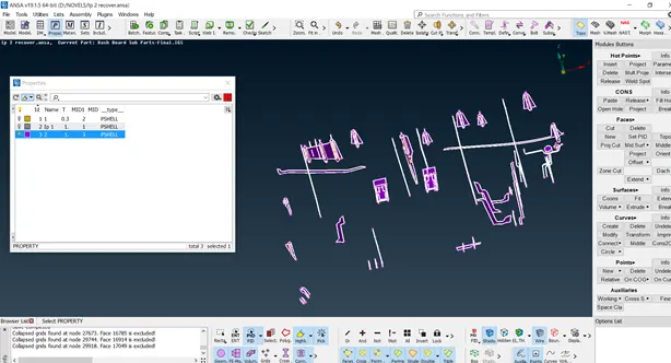
- Here the above figure represents the mid surface of the interior part of dash board
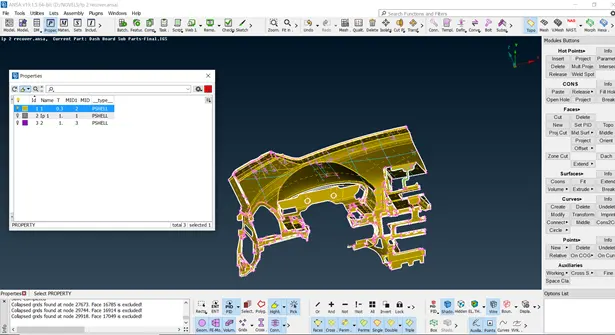
The above figure represents the midsurface of the top layer
(MESH>QUALITYCRITERIA>VALUES>PRESENTATION PARAMETRES>ELEMENTSPERCENTAGE>OK?>DEMANDDRAFT TO LEAST PERCENTAGE)
- After the quality parameters meshing parameters are to be evaluated in which the mesh size is entered
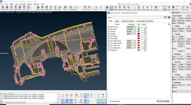
(MESH>MESHPARAMETRS>GENERAL>MIXED>1STORDER>AVERAGELENGTH>MIN= 2>MAX =6)
- Overall mesh length is taken and applied the mesh length of 4
(mesh>faces>length=4)
(MESH>PERIMETRE>LENGTH>PERIMETRE>LENGTH=4)
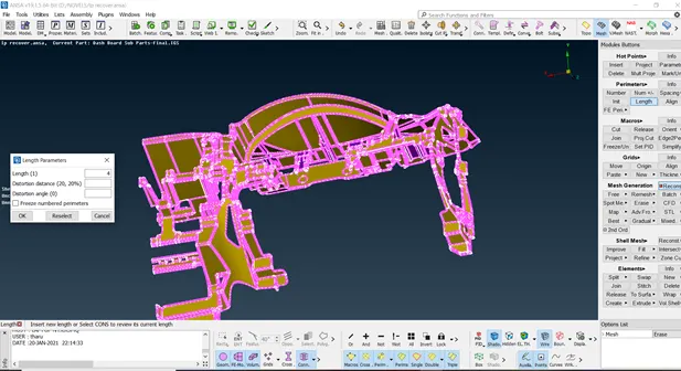
IN THE ABOVE FIG THE APPLICATON OF MESH LENGTH IS SHOWN
- Applied mesh length is not equally mesh on all the surface where the mesh adjustments are done at the complex areas
Mesh length adjustment
(mesh> select areas where the length is less than 3>faces>delete>length>5)
- unequal nodes are deleted for the requirement of the average length of the mesh
- The geometrical model here meshed by using the best option
The hood model is divided into the imaginary square boxes using the cut option for the better meshing
BEST: It is the option used for the meshing the surfaces which are selected a surface by
surface
- MESH>MESHING PARAMETERS>BEST>SELECT THE REGION> OK
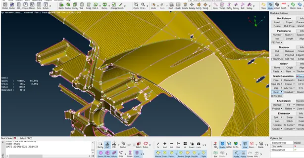
Here in the above fig the mesh is applied on the selected region using the best option
- After creation of mesh over the surface it is wrapped in different in quadrilaterals and triangles
Here the triangles are reduced to the quadrilaterals by using split option
SPLIT: it is the option used for the conversion of the shape of the mesh element trias here are converted to the quads
RECONSTRUCT:
Here the reconstruction of the mesh can be done where the major areas of the trias are converted to the quadrilaterals
(mesh>shell mesh>reconstruct>select the area>middle click of the mouse)
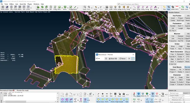
The application of the reconstruct tool is shown
- SMOOTH : This option is used to for the smoothing the meshed surface this does not change the meshed elements but makes the meshed surface smooth
Which decreases the offset elements.
After meshing the overall model
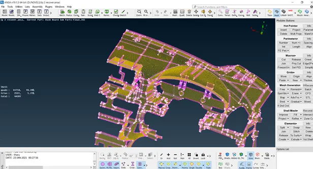
The above fig represents the complete meshing of the component
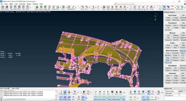
OUTCOMES
- Learnt how to check the geometrical errors
- I learnt how to extract of the mid surface for the model
- Applying the fine quality mesh for the given model
CONCLUSION: For the given hood model the overall quad %=94.28
The trias %=5.72
The link of the model is attached below look into it
https://drive.google.com/file/d/1mD6cPruiQ11FLuCqwF6Ln_JQbO2X7xxB/view?usp=drive_web