Week 4-1D Element Creation Challenge
AIM:
- To take the midsurface of the given model
- Mesh the given model with the given element size
- Provide the necessary rigid connections using different elements
SOFTWARE USED:
Hyperworks 2020
PROCEDURE:
- IMPORTING THE CAD MODEL
The given cad model is the format of .iges it is imported by using the import option
(File > Import > Geometry drop-down menu )
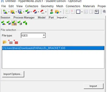
Fig : the above picture shows the importing the cad model
- check for the geometry
Necessary geometry checks are done
- Midsurface
Here the whole component is converted into the 2d geometry by taking the midsurface which is used for the easy evaluations
Mid surface is taken for the one component using midsurface tool . here , the extraction option is used for the selection of type of midsurface . this selection is based on the type of result required for the given geometry
For the given cad model skin is selected as extraction and by selecting
the surface the midsurface is taken
(geometry>midsurface>extraction tool>skin>auto extraction>surface selection>extract>)
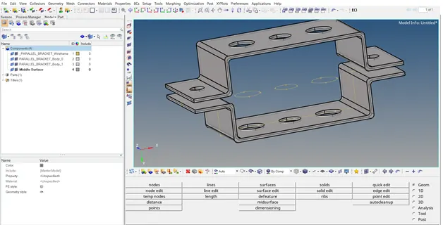
Fig : the above picture shows solid surface which included the midsurface
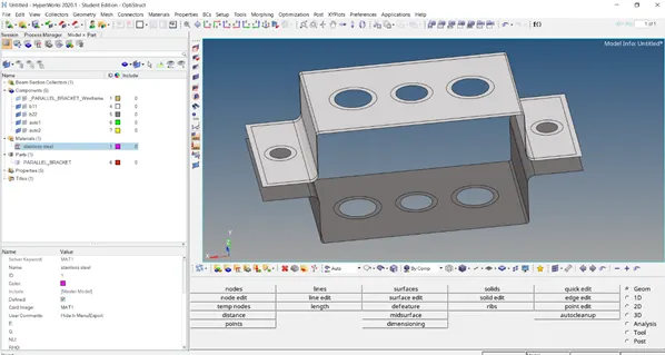
Fi
Fig above shows the the overall midsurface of the component
- After the midsuface is done to view only the midsurfaces the solids part of the geometry is deleted by the delete option or using the entity panel the 3d surfaces are deleted
(components>select the 3d planes > right click > delete)
- The whole midsurface is viewed in only one component which is to segregated by creating the new component and moving the new component (utility menu>left click >create>component >rename> b22)
- Organise: it is used to move the components(tool> select the component> check the path of the component > ok)
By this the components are divided into the individual components
- Material creation
Assigning the material is done for the . selection of the materials includes the density , youngs modulus , etc.,
Here, the material is created as a stainless steel
(utility menu> create> material> ok> rename> stainless steel > ok > card image = mat 1 >ok)
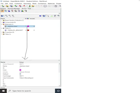
- Property
The property here is used display the type of element selection and the thickness etc.,
(utility > create > property> rename> b22>thickness 2.5>material = select the s.s>ok)
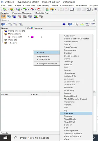
Fig showing the creation process of property
After the creation of the materials and the properties in the utility menu those are assigned to the cad model in the form of the property selection
(utilty menu > components> b22>property > select the property >b22>ok)
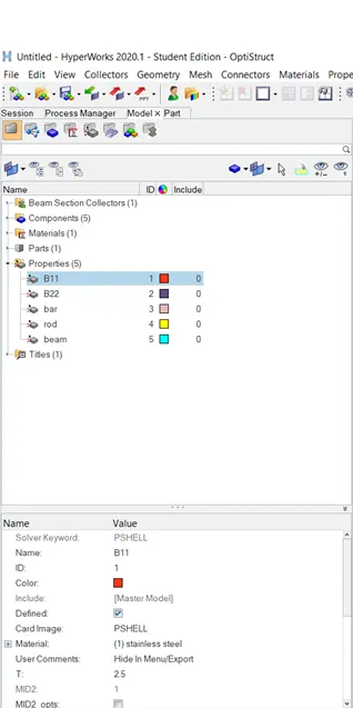
Fig above shows the b11 and properties assigned to it in below
- Washer elements
Stress concentration near the holes are avoided by creating the washer elements.
(geometry >quick edit>washer split>size= 5> select the holes >ok)
- Meshing
The whole components is divided into the elements by creating the mesh on the components. The elements created are of equal size and similar type
(2d elements> automeshing > select the surface>create)
Thus the meshing is created over the components
- Quality of the mesh
The mesh quality need to be adjusted for the good evaluations .
At the holes washer elements the mesh quality is addressed by creating the nodes or eliminating
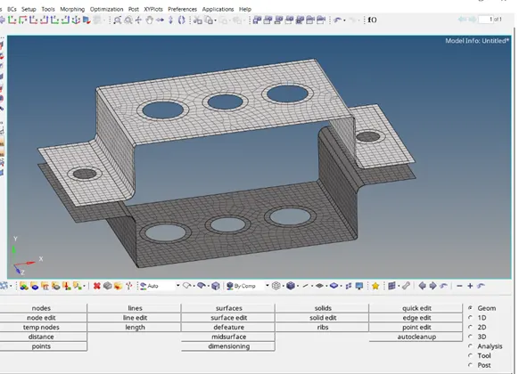
The above fig the model after meshing
- RBE2 & RBE3 ELEMENTS
Rbe2 and rbe3 are the rigid elements which helps to rigid the movement in particular direction
The main difference between the rbe2 and rbe3 is the distribution of the load . in the rbe2 the load distribution is done equally throught out the element where in the rbe3 the losd distribution varies from point to point
- Creation of the rbe2 element
Select the nodes by the path and create the rbe2 element on the junction a
In the bottom of the bar we find the 2 rows and 3 colums which represents the rotational and the translation of the x y & z axis
For the junction a constrain the translational
(1d > rigid element> select the holes> nodes> by path>ok>un boc the rotational >ok)
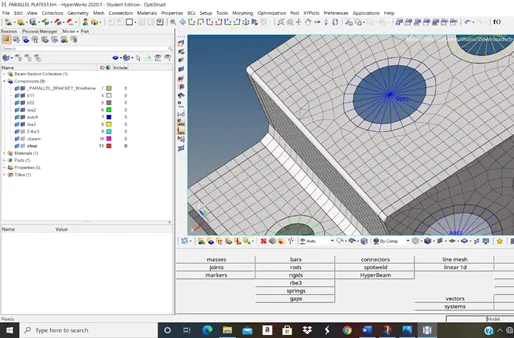
The fig shows the rbe2 element
At the junction b
At this point the rbe3 element is created which is constrained in all translational and the rotational .
(1ed >rigid elements>rbe3 >nodes> by path > ok)
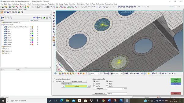
The above fig shows the rbe3 element
At the junction c
Here, the axis is constrained in the x and y axis are constrained for the rotational &tranaslations
- CREATION OF CROSS SECTIONS
HYPERBEAM : It is used to create the different types of cross sections namely L ,T ,X , CIRCULAR etc.,
Optistruct type is selecte as an solver
(1d element > hyperbeam>standard section>optistruct>ok>create >property> select the I as shape> give a , b , t values>ok)
As according to the instructions followed it forms the I shape
Rest of the two elements are also created accordingly to the dimensions provided z
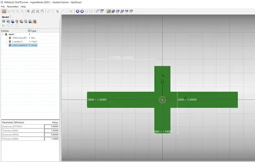
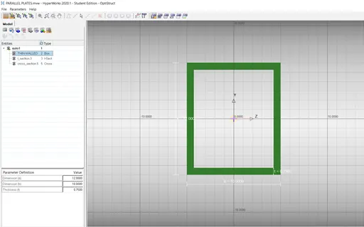
the above fig shows th cross sections pf thicked wall and box
- CREATION OF ROD , BAR AND BEAM
- Create the 3 individual propertiers namely rod , bar and beam
ROD
- At junction a join the rbe2 element s using the the rod element
(1d >rods>create select the nodes> ok)
- The line is formed between the two nodes displaying as c rod
- For the 3d rod the property rod should be assigned with the cross sections and the element
(utility bar> properties>rod>select the card image = pbar >beam section = thin walled section>ok)
- After assigning the property
(rod>update> select the element as rod>select > rod > tick the boxes> ok)
- thus the cross section is applied to the c rod element
- for the 3d view of the given cross section at that junction can be viewed by selecting (1d detailed presentation>ok)
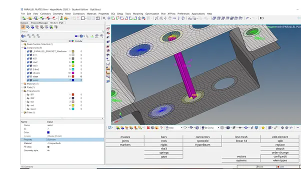
The fig shows the cbeam representation
And the rest of the two beam and bar is followed the same procedure
- creation of the spring element
for the evolution of the spring connection selection of two nodes are done of different planes
(1d >springs >nodes>create)
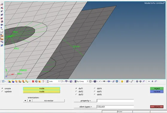
The fig shows the cleas (spring ) element
- applying the mass
For applying the mass the rbe2 or rbe3 nodes are created at the d & e junctions
The nodes are joined by rbe2 element and for applying mass mass option is used where the value is given at the mass column
(select the holes> rbe2> nodes > by path > create)*2
(Masses> select the node>component>mass >10>ok)
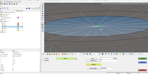
The above fig show s the rbe2 connection and cmass application
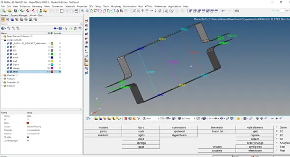
The overall model before translationto 2d
The overall view of the model
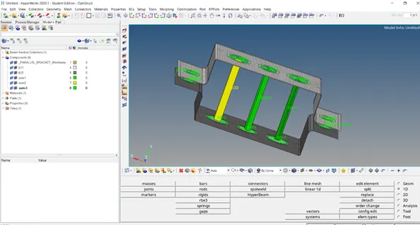
The above fig shows the overall fea model
Out comes
- learnt how to take the midsurface of the component
- assigning the selective materials and properties
- applying the masses
- creation of cross section and assigning them to the properties
- making the rigid connections
check the model which is enclosed in below link
https://drive.google.com/file/d/1kzfkRLoJTv6F8Mvxz0nCDlZKLZFeRAOP/view?usp=sharing