Week 9-Creation of 1D Connectors Challenge
Aim:
- Mesh the given frame assembly model.
- Make the connections between two surfaces using the connectors
Software used:
Hypermesh 20202
Procedure:
Import: import the frame assembly model using the utility tab
Delete the solids:
The solids are deleted using the delete option
(delete>solids>displayed>ok)
Meshing:
All the components in the model are meshed using the quad elements
(2d>automesh>select the surface>element size 5>quads>ok)
Qi
(2d>element criteria>edit criteria >enter values>ok)
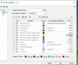
Above image shows the quality criteria
Mesh editing
After the mesh is applied all the elements are adjusted to minimum and max lengths using the quality index tools
The meshed is edited so that the elements could satisfy all the below criterias
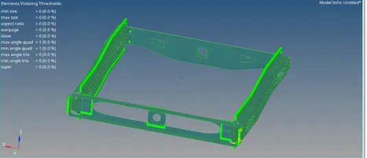
Above image shows the meshing after clearing the quality failures
Connectors
They are actually used to combine two different surfaces .the connectors helps in distribution of loads
When the load is applied on one among the two surfaces which are connected by connection . this connectors acts as a barriers of loads
Based on the type of application , areas the connectors are classified in many in which seam, spot are used more
Seam and spot implies the type of welding
Connection 1(right rail 2 and front rail 1)
Seam quad (l type)
- This is used when the two surfaces are parallel to each other
- 2d>connectors>seam>quads>nodelist>bypath>tolerance=10>spacing=5>run angle 10>cap angle 75>weld angle 60>total 2>property lr 1>components>select rr2 fr1>create.
- If the element is failing for quality the elements are meshed once again to get rid of failures
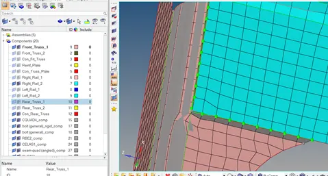
In the above image green nodes the connection between two surfaces
Connection 2
(left rail 2 and front rail 1) Seam quad (l type)
- 2d>connectors>seam>quads>nodelist>bypath>tolerance=10>spacing=5>run angle 10>cap angle 75>weld angle 60>total 2>property lr 1>components>select rr2 fr1>create.
- Remeshed if the elements are failed for quality
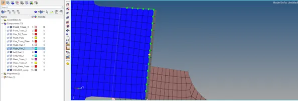
In the above image green nodes the connection between two surfaces
Connection 3
Front truss 1 and front truss 2 and right rail 1
- The above components are connected by the spot weld
- 2d>connectors>spot >nodes>by path>property lr 2>type =plot>spacing =5>compo>total 3>select the 3 compos>dia -5>create
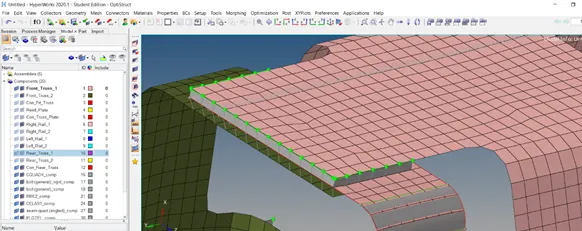
The above image shows the connecrion of 3 compos using spot weld
Connection 4
Front truss 1 front truss 2 left rail 2
(hexa adhesive)
- the above components are connected by hexa adhesive
- 2d>connectors>seam>adhesive>nodelist>by path>spacing 5 >type hexa adhesive>tolerance=10>select the 3 compos>create
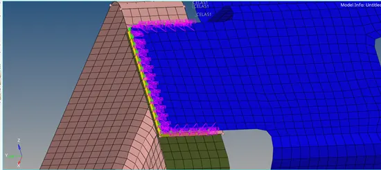
The above rbe3 elements shows the adhesive connection
Connection 5 and 6
(bolt connector)
Rear truss 1 &right rail2,rear truss 2 &left rail 2
- The above components are done using bolt connector
- 2d>connector>bolt>nodes >select nodes at bolt connection >type= bolt>tolerance =10>create bolt if none>adjust the hole position>create
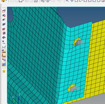
In the above fig the two surfaces are joined by bolt connection using rbe2 elements
Connection 7
Right rail 1 and right rail 2
- the above components are connected by rigid elements using type spot weld
- 2d>connectors>spot>type= rigid >tolerance 10 >location = nodes>by path>compos2>dia meter 5>find the nearest nodes>create
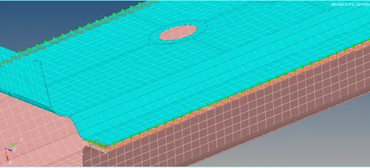
In the above the surfaces are joined by the rigid elements
Connection 8
(spring element)(left rail 1 7&left rail2)
- in the connections it is denoted by clease (eleastic)
- 2d>connectors>spot>type= spring >tolerance 10 >location = nodes>by path>compos2>dia meter 5>find the nearest nodes>create
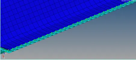
In the above fig the spring connector is used to join the elements
outcomes
- Learnt how to connect the surfaces using the different types of welds
- Learnt the importance of term weld angle , height ,spacing in the welds)