Assignment 4-RADIOSS Material Laws Challenge
Aim:
- To analysis the rupture plate by using the different material cards under different condtions in the radios
Softwares used
Hypermesh 2020, hyperview , hypergraph 2d
Procedure
Case 1
Johnson cook material :it is mainly used to study the plastic deformation case of the shell elements
Import
- Import the johnson failure .000rad file using the import tool from the tools bar
- The model is directly runned for analysis without any change
- (analyse>radios>include all the connectors>-nt 4>save as >failure johnson_0000.rad file>ok
- Open the file(failure johnson_0000.out file) in the notepad check the energy errors checked it is either under -15%
- As the failure card is defined for the model the elements gets deleted after exceeding the uts (maximum stress limit)
- Failure card contains values for D1 D2 D3 for the compression , tensile loads
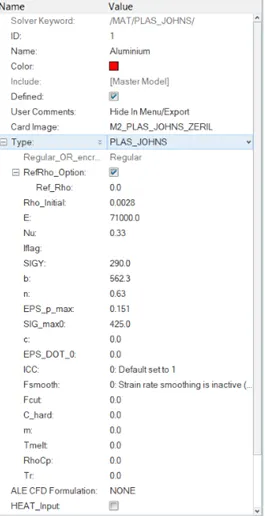
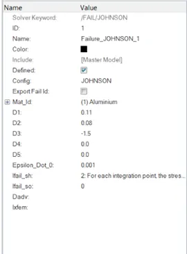
fig showing the material card and law o2 failure card with no values defined
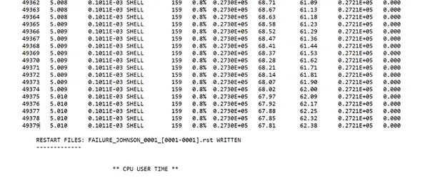
Fig showing the energy errors
Hyper view
(import>.h3dfile>apply)
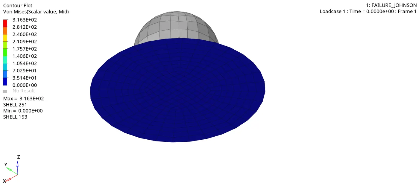
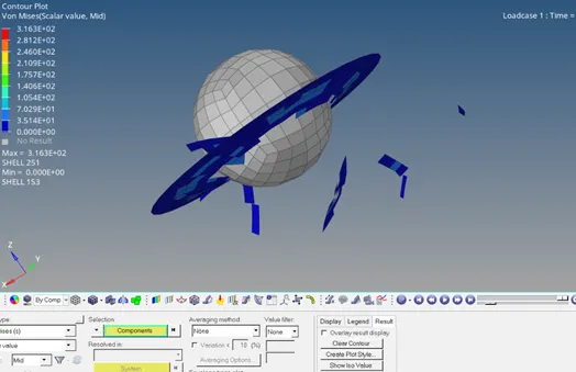
Fig showing the element failure in the hyper view
(hyper graph 2d)
(change to hyperview 2d>import>T01.file >global varibales>KE, TE,IE,HE>magnitude>apply
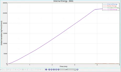
Fig2 showing the graph plotted between the energies vs time
Rigid wall forces
(hypergraph>rigidwall forces>totol energy>Apply)
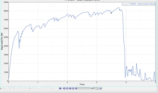
Fig shows the rigid wall forces
Case 2
- Import the same parent file used in the case 1.
- Assign the values given for the material selected (Dadv=1, Ixfem=1 ,Ifail -sh=1)
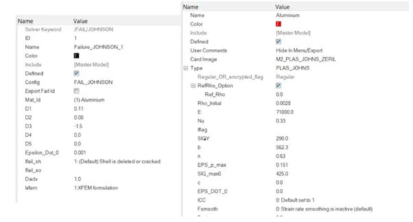
- Dadv comes into access only when the Ixfem is defined the term
- Ixfem is to define the crack initiation
- .Dadv it is the damage value where the crack is intitated.
- (analyse>radios>include all the connectors>-nt 4>saveas >LAW02 EPS MAX >ok
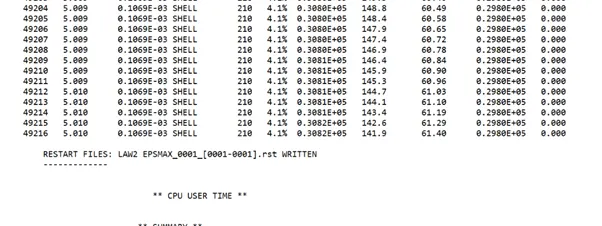
Fig showing material table with values defined
- Hyper view
- (import>.h3dfile>apply)
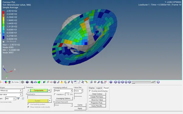
Fig showing the element failure in the hyper view
- (hyper graph 2d)
(change to hyperview 2d>import>T01.file >global varibales>KE, TE,IE,HE>magnitude>apply
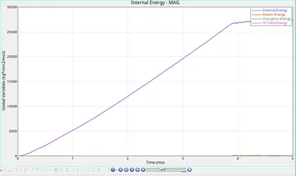
- Fig2 showing the graph plotted between the energies vs time
- Rigid wall forces
(hypergraph>rigidwall forces>totol energy>Apply)
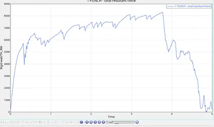
Fig shows the rigid wall forces
Observations found when Comparison of case 1 and case 2
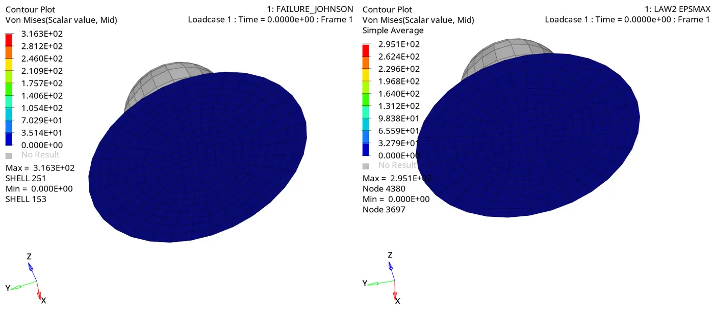
case 1 case 2
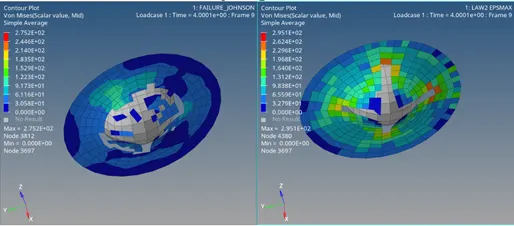
Fig comparing the case 1 and case 2 file in hyper view
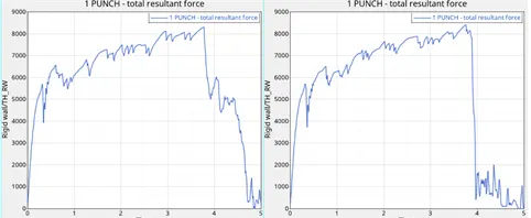
Fig comparing the rigidwalls for case 1 and 2
- From the .h3d file comparison it is found the the elements are getting deleted after reaching the Eps max .and also found the stress rate is high in the case 2 due to cracks developed
- From the TO1 in the energy graphs it is found the elastic limit is achieved upto 3.9 but in the case 2 it is found at 4.5
- From the rigid walls graphs in case 1 it is shown the energy is decreased drastically at once when it reached to max but in case due to the crack evolution the energy are decreased In a non linear way.
Case 3
Deletion of the failure card
- Failure card is deleted from the parent file
- EPS Max value is added at the 15%
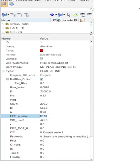
Fig shows the eps max value 15%
- when the EPS value is reached to that limit .elements directly get deleted
- (analyse>radios>include all the connectors>-nt 4>saveas > >ok
hyperview
- Hyper view
- (import>.h3dfile>apply)
-
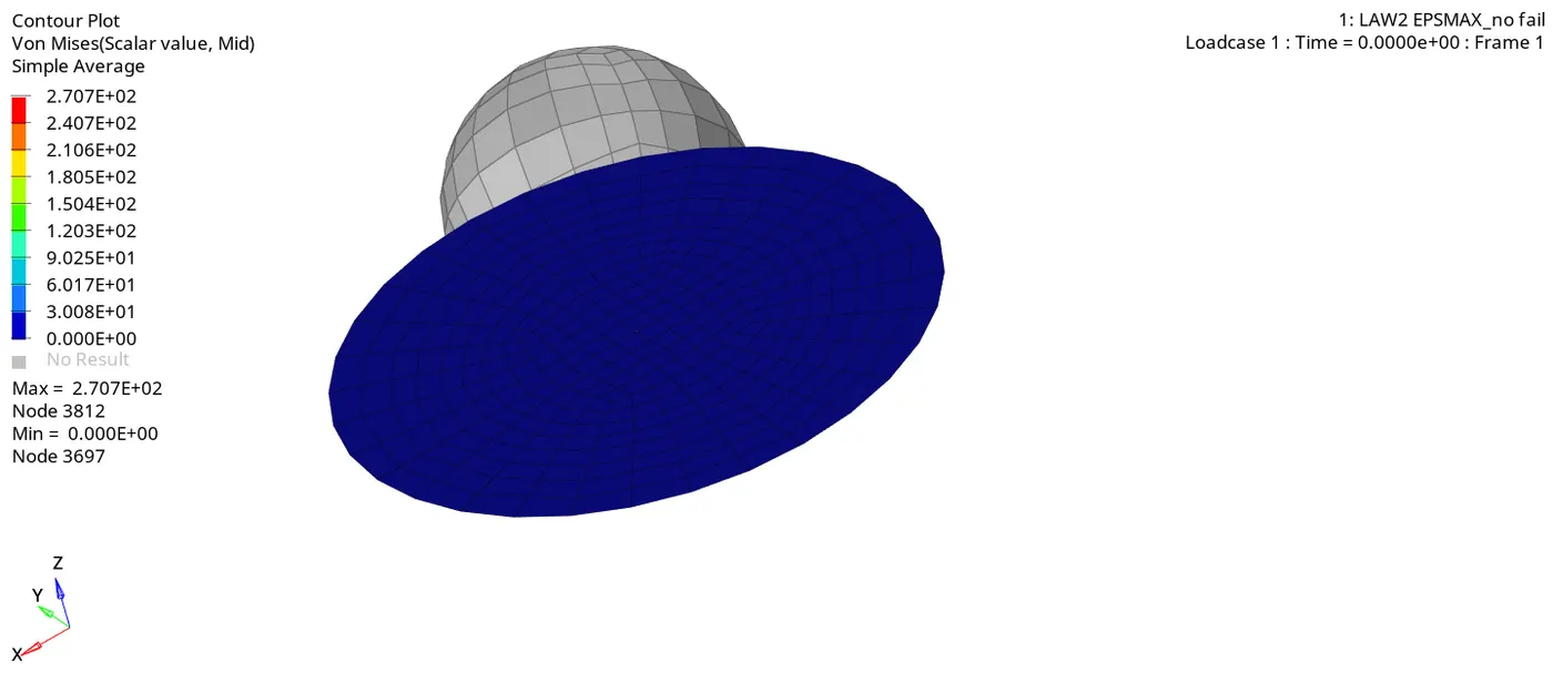
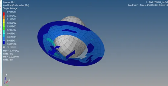
Fig showing the element failure in the hyper view
- (hyper graph 2d)
(change to hyperview 2d>import>T01.file >global varibales>KE, TE,IE,HE>magnitude>apply
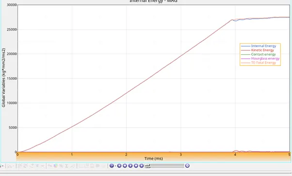
- Fig2 showing the graph plotted between the energies vs time
- Rigid wall forces
(hypergraph>rigid wall forces>totol energy>Apply).
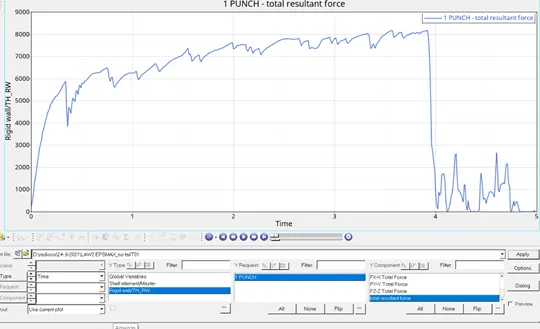
Fig shows the rigid wall forces
Case 4
- Delete of the failure card and eps max =0
- Import the failure johnson model and delete the failure card
- Set the EPS Max value =(0): by default it considers 10^30
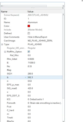
- material card
- The material behaves like elastic material
- The deletion of the elements is not happened because of its high uts point
- (analyse>radios>include all the connectors>-nt 4>save as >epsmax >ok
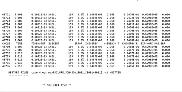
hyperview
- Hyper view
- (import>.h3dfile>apply)
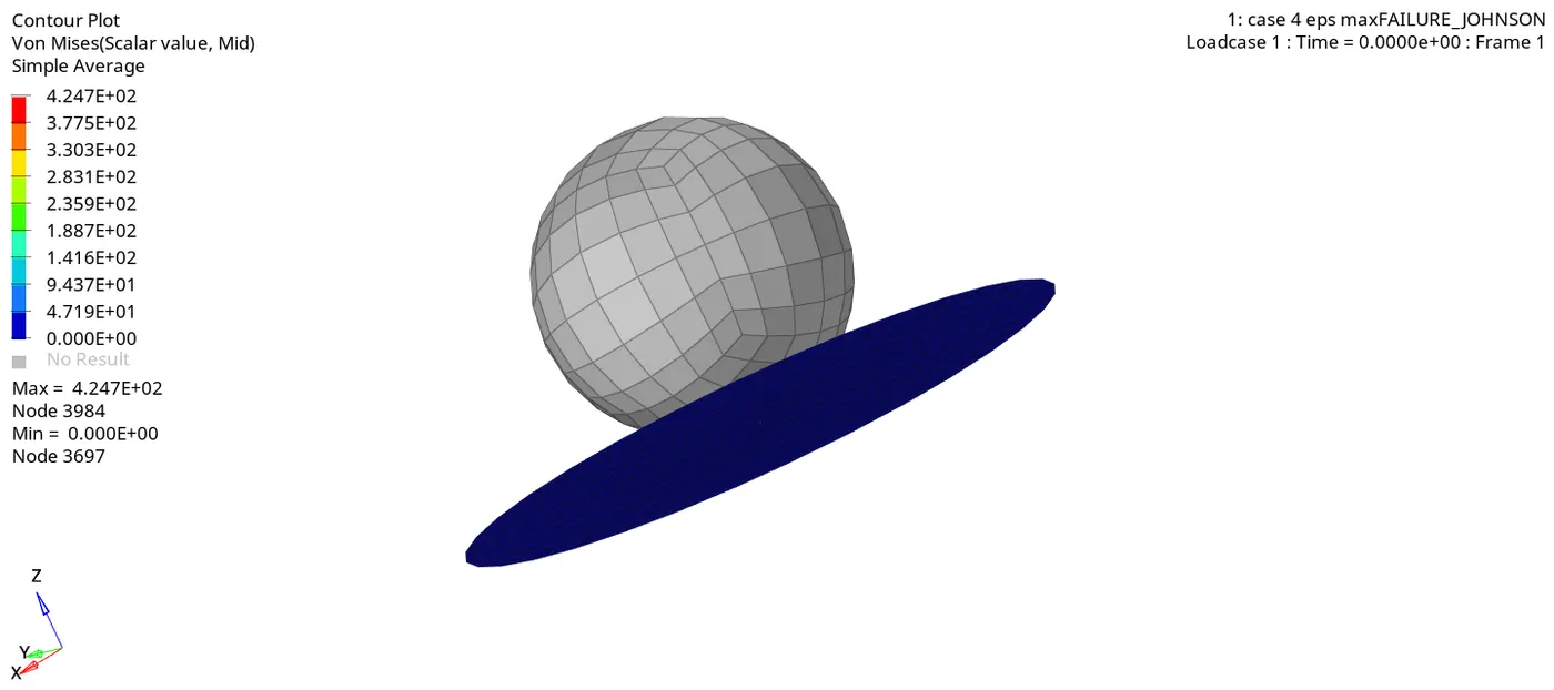
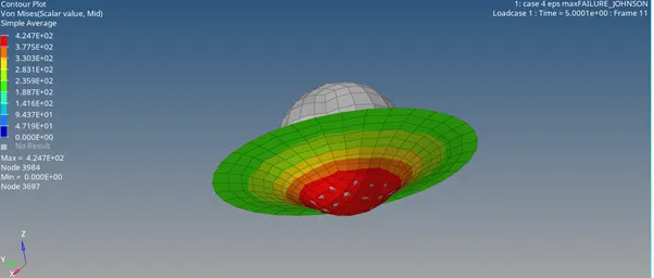
- Fig showing the element failure in the hyper view
- (hyper graph 2d)
(change to hyperview 2d>import>T01.file >global varibales>KE, TE,IE,HE>magnitude>apply
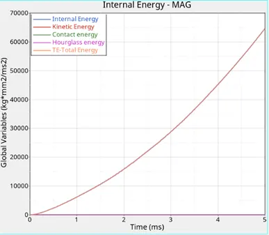
- Fig2 showing the graph plotted between the energies vs time
- Rigid wall forces
(hypergraph>rigid wall forces>total energy>Apply).
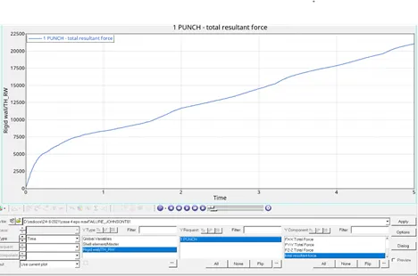
Fig shows the rigid wall forces
Comparison between case 3 and case 4
- In the case 3 the elements gets deleted in the when the eps max value when the case 4 the elements are strained untill it reaches to max epx (1030)
- In the case 4 the stress value (vonomosis) found maximum compared to the above 3 cases
- From the rigid walls graph in the case 4 as there is no uts point stress value is not decreased but it is opposite in the case 3
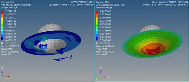
Fig showing the element destrotion in case 3 and 4
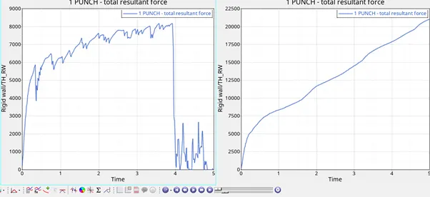
Fig shows the comparsion in rigidwalls in case 3 and 4
Case5
- Import the failure johnson _0000.rad file
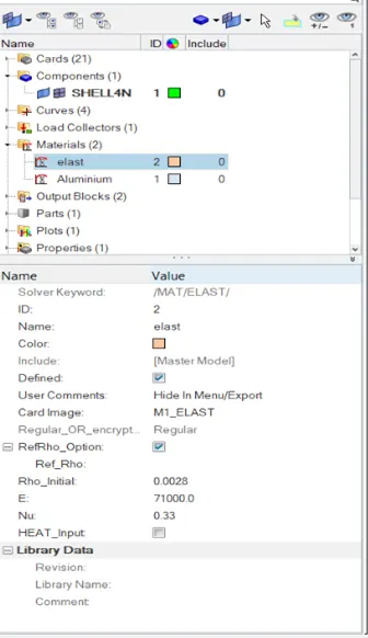
- Create the aluminium material and the foe theM1 ELASTIC
- For the elastic material and the enter the value of the density , poisson ratio , young modulus value
- E=71000,MU=0.33,Initial density =0.0027
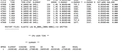
- Analyse>radios>saveas>elast>-nt 4>include collectors>ok.
This are used in the rubber applications .
hyperview
- Hyper view
- (import>.h3dfile>apply)
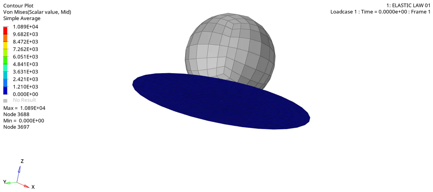
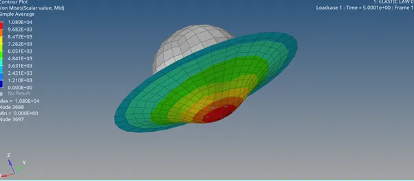
Fig showing the element failure in the hyper view
- (hyper graph 2d)
(change to hyperview 2d>import>T01.file >global varibales>KE, TE,IE,HE>magnitude>apply
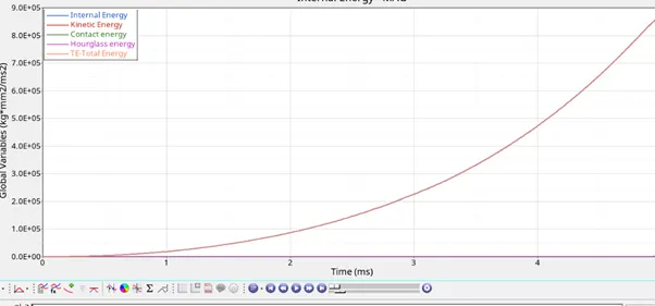
- Fig2 showing the graph plotted between the energies vs time
- Rigid wall forces
(hypergraph>rigid wall forces>total energy>Apply).
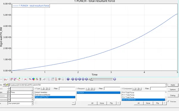
Fig shows the rigid wall forces
Case 6(PLAS_TAB)
- It is the hybrid of the law 01 and law 02.in this type it runs both the shell and the strain
- Here, the true strain stress values are entered to compare the evaluated values the experimental values are entered using the material card
- Import the law_0000.rad file in to the data base .
- Select the material card to the law36(elasto plast )tab and enter the necessary material and property card details
- The true stress and strain is created for the material selected based on the experimental values E and g values are entered .
- (curve >create>new>enter the nu and e values >ok>x and y function fscale >1.0epsdot>1.0>ok)
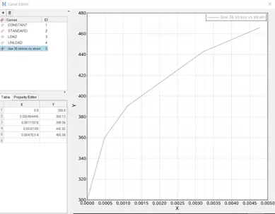
Stress vs strain curve
- Select the material
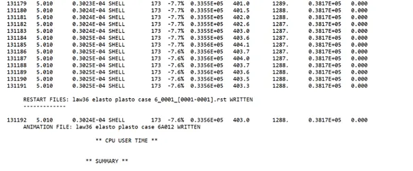
- (analyze>radios>-nt 4>include collectors >save as >elasto plasto law 36>ok
- Hyper view
- (hyperview>select the h3d file>ok)
- (the elements are deleted from the centre when the strain rate in the elements reaches to the value defined EPS max =16%
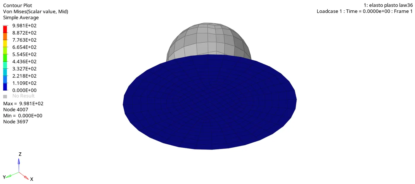
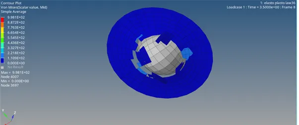
- Fig showing the element failure in the hyper view
Hyper graph 2d
(import>select the to1 file >apply
(hypergraph>global values >te,ke,he,ie>mag>apply)
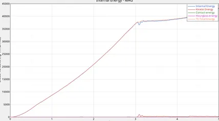
Rigid wall forces
(hyper graph>rigid wall >total energy>apply)
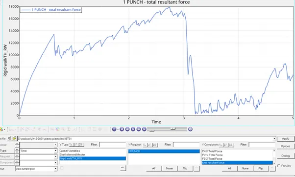
Fig shows the rigid wall forces
obervatoins
1.from the above graphs it is observed
Case 7 (LAW 27 _0000. FILE )
- Import the law27-0000.rad file into data base.
- (analyze>radios>-nt 4>include collectors >save as >brittle 27>ok
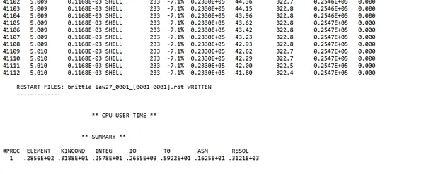
- After running the model check the energy balances and the energy error
- Here, when the stress reaches the ultimate tensile stress the element directly gets deleted . it also delete the elements attached to it
- There is no elasticity seen in this type of material card
- The applications of this material card is majorly seen in silica, glass, mica etc.,
hyperview
- Hyper view
- (import>.h3dfile>apply)
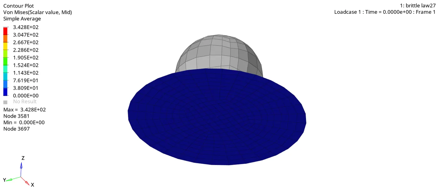
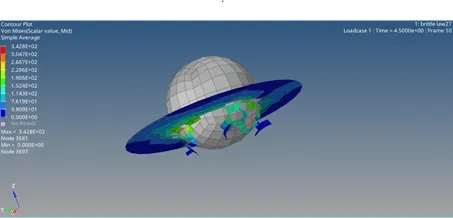
Fig showing the element failure in the hyper view
- (hyper graph 2d)
(change to hyperview 2d>import>T01.file >global varibales>KE, TE,IE,HE>magnitude>apply
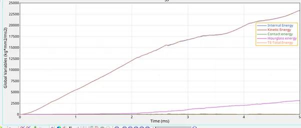
- Fig2 showing the graph plotted between the energies vs time
- Seen hour glass is deviated from the zero it is just because of the type of the mesh selection hourglass is limited upto only certain limited value
- Rigid wall forces
(hypergraph>rigid wall forces>total energy>Apply).
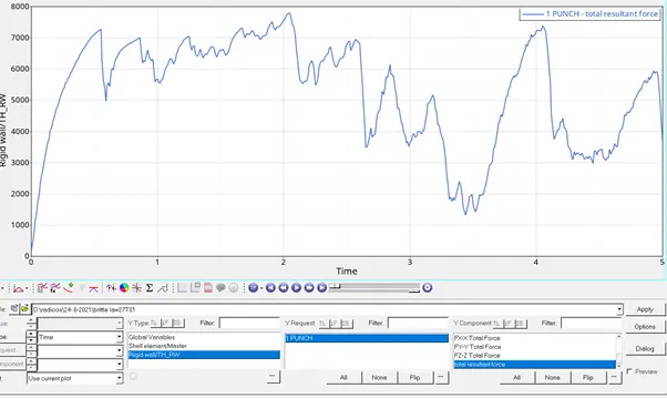
Fig shows the rigid wall forces
from the graph it is observed that there is not particular uts point in thus type of analysisi , in the brittle type materials the elements gets ruptured on the point of contact
. there are no particular eps or uts points
conclusion
As we know the rupture plate is material which should get too elastic or too brittle in the nature . as it is a one time usage it undergoes heavy pressure on it it ruptures when
the uts point is reached out ,by the elimination of all above cases plasttab law 36 is the perfect application for the rupture plate which ruptures reaching the maximum stress
limit .
outcomes
1.learnt how to run the and anlysis the starter file using the hm tab
2.learnt to observe the max stress points using the vonmosesis eqn in the hyperview
3.learnt how to plot the graph between the eergies and the rigidalls in the hypergraph 2d
4.learnt how to create the different materials based on its E ,G and mu values .