Assignment 2-RADIOSS Engine File Editing & 3D Meshing Challenge
OBJECTIVE
- Check the material properties of the rail component and calculate the speed of sound in steel rail:
ANS
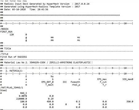
Image shows the .0000rad intial file
- From the given starter file E=210000, ρ=0.0078:
- Speed of the sound c= √ (E/ ρ)
- By substituting we get c= √(210000/0.0078) =5188.75mm/ms
- The length of the rail is about 1000 mm.calculate the time takes for a shock wave to travel from one end of the rail to the other.
Ans :
- Given L=1000mm
- Time taken (dT)= length /sound speed
- dT=(1000/5188.75)= 192724645 ms
3.Time for sound to travel length of rail=______
Ans :
time taken to travel the total length of the rail is (dT =0.192724645 ms)
4.Edit the engine file so that the stress wave can be monitored, moving from one end of the rail to the other during impact -this will require a termination time equal to the time it takes for the sound to travel the length of the rail(set on/RUN card)
5.Set the frequency of animation output to a time that will give 20 animation steps(/ANIM/DT)
Ans :
- T freq= dT/(number of animation steps)
- T freq=192724645/20=0.00963623225
6.Change /print -10.
- N- PRINT = 10
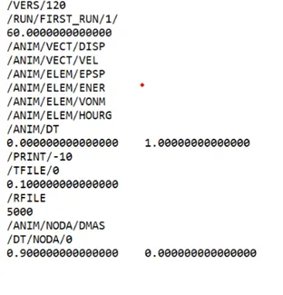
Before edit
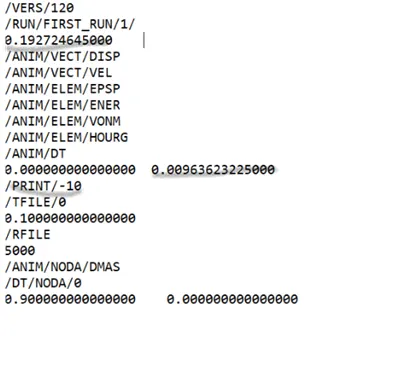
After edit
7.
3d meshing tetra mesh and hex mesh
- Repeat class examples and, maintain the quality.
- Target tet size=5mm,hex size=10mm,tet collapse=0.15.
Procedure
Import :the model is imported into the graphical area
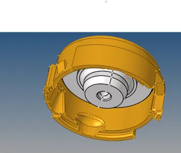
Import image
Measure :the thickness of the component is measured at the different point if the thickness is found above 6mm 3d mesh is to selected
3d meshing : it is the meshing done on the component without taking any mid surface the mesh is developed
- view>browsers>hypermesh>utility>quickmesh>tetra mesh>component>select
the component>enter the size=5>mesh>ok
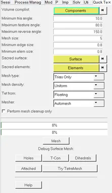
Image shows Quick tetra mesh tab
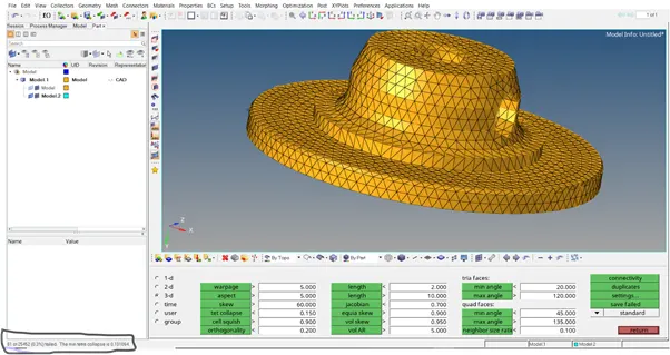
Image shows the tetramesh image included tet collapse elements
- quality criteria for the 3d elements are checked
- tet collapse is checked
(tools>check elements>3d>tet collapse>check elements)
- the tet collapse elements are sorted by remeshing the tet elements
- (tetcollapse elements>savefailed>mask>elements>retrive>mask>reverse>ok)
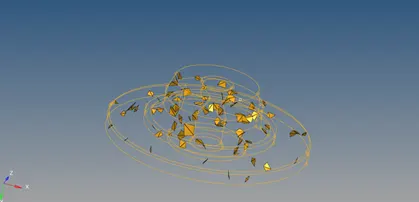
Image shows the individual tet collapse elements
- (3d>tetramesh>remesh>edit the tetra mesh parameters>remesh>ok)
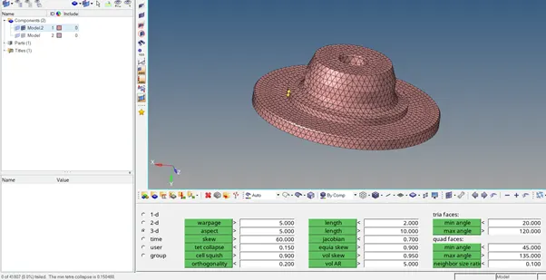
Image shows the tetra mesh image after sorting the tet collapse
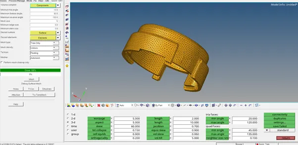
Image of hub after tetra mesh
HEXA MESHING
IMPORT : import the arm bracket model into the graphical area
Procedure:
- Check for the geometrical errors and open edges in the model
- Meshing
(select the arm base surface>2d>mesh>quads>element size = 10>ok)
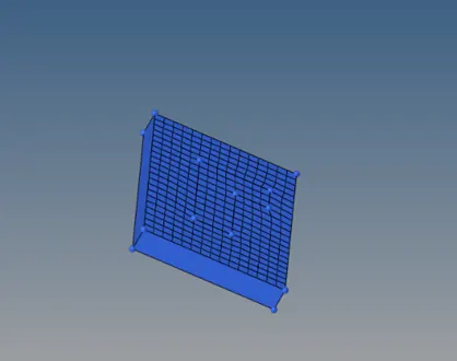
Image show the 2d mesh on the arm base
- 3d mesh
Element offset
3d>element offset>select the elements>select the destination surface>select the layers based on the thickness>select the line as along surface>drag)
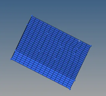
3d mesh on the arm base
2 spin
- As the geometry is in circular the meshing is done by using spinning the elements
- Create the center for the curvature as arefrence point
- (tools >measure>select the 3nodes on the line>ok)
- 3d>spin>select the elements>angle 90>base point circle center >select the layers as 25>drag)
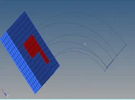
Before spinning the elements
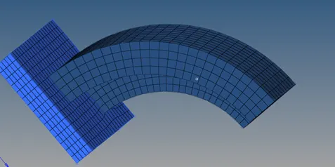
3d mesh image after application of 3d spin tool
3.linear solid
Here, the elements are mapped from the surface to the destination
- Create the mesh at the end of the surface which should be equal in number to the reference elements from the surface
- 3d>linear solid>select the refrence elements>select the destination elements>number of layers 12>ok
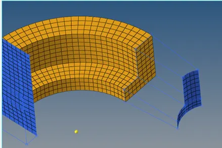
Before applying linear solid
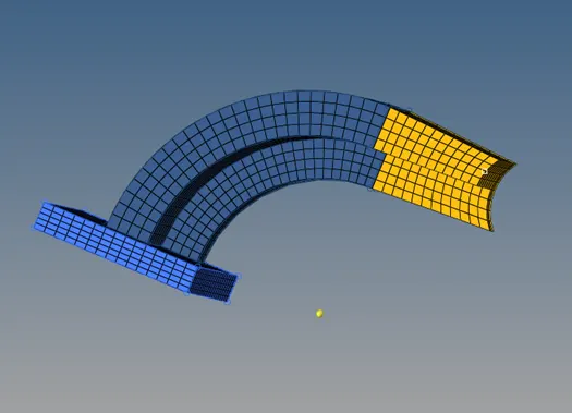
Image after linear solid (mesh mapping)
- Solid map(general)
- Create the mesh on the circular part of the cylinder
- 3d>solidmap>select the source elements >select the destination surface>number of layers >select the mixed option from>select the reference line >select the node path to be followed by the elements>ok)
- The elements are found for any open edges and elements are equiavalenced
- (tools>edges>select the elements>preview equivalence >ok
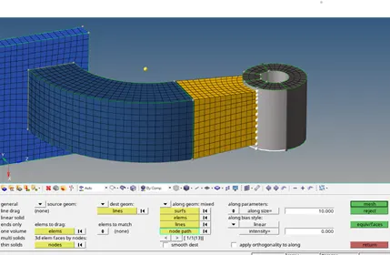
Image showing the reference points for the mesh path
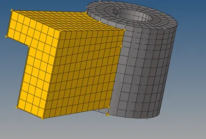
Image after applying the solid mesh
Delete for the faces
Here, the 2d faces created while meshing are deleted
( tool>face>find faces>select the faces and delete the faces)
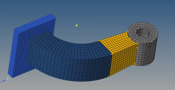
Overall image after hexa meshing
Outcomes:
- Learnt how to mesh component using the quicktetra mesh tab
- Learnt how to mesh the model using the hexa mesh